Hood design-Week 2
HOOD DESIGN USING NX CAD
OBJECTIVE:
To understand the basics of BIW (Body in white) by designing the hood of a car by following the design parameters and master section provided.
INTRODUCTION:
We study how to design a hood inner panel and outer panel, positioning the hinges, strikers, and reinforcements using the Siemens Nx CAD tool.
Using these tools and all the design principles we design the Hood.
WHAT IS BIW?
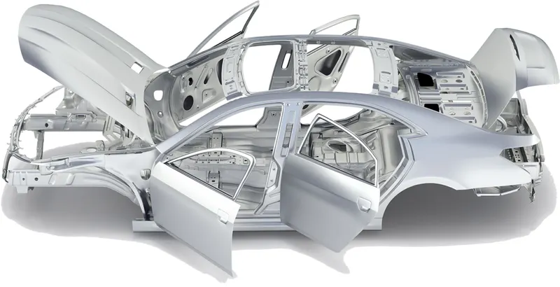
Body in white (BIW) is the stage in automobile manufacturing in which a car body's frame has been joined together, that is before painting and before the motor, chassis sub-assemblies, or trim (glass, door locks/handles, seats, upholstery, electronics, etc.) have been integrated into the structure.
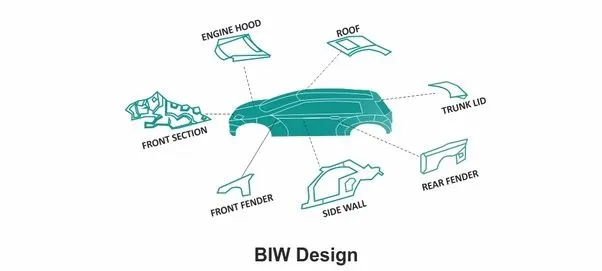
Creating a BIW structure using a solid approach involves the creation of solid features in which the shape of one side of the metal is developed. Typically a large solid is created to capture all required faces. Once the solid is complete, the Shell command is then applied to create the sheet metal thickness.
MATERIAL SELECTION:
Of the five materials for car bodies, steel is the most widely used, followed by plastic, aluminum, and fiberglass, which is currently less commonly used on SUVs. In addition, for some high-end vehicles, magnesium and carbon fiber components are beginning to integrate.
BIW is expected to possess a number of significant properties. It must have high tensile strength as well as high stiffness-bending, torsional, static, and dynamic. It must also provide good quality safety both to the car body and to its occupants against crashes of all kinds-front, rear, side, or even roll over, meeting the Federal Motor Vehicle Safety Standard No. 208 [44]. It should also be able to protect occupants from noise, vibration, and/or harshness (NVH) by absorbing or reducing these conditions. Also, it should be easy to weld and form, as well as be highly paintable and easy to design. It should provide a good surface finish that is smooth, and should also be corrosion resistant. Improvement of fuel economy also necessitates the use of lightweight materials in BIW, as it constitutes a significant share of car's weight; in addition, given environmental concerns in recent times, it is also expected to be recyclable. Given such extensive requirements, only steel and aluminum have been used for making BiW; the former is preferred for its high strength and low cost, while the latter is preferred for its lower density that helps reduce car weight.
HOOD:
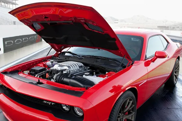
A car hood also referred to as a bonnet in some other countries is the hinged cover that rests over the engine of a front-engine vehicle. Its purpose is to provide access to the engine for repair and maintenance. A concealed latch is typically used to hold down the hood. On vehicles with an aftermarket hood and on racecars, hood pins may be used to hold down the car hood. Hoods sometimes also contain a hood scoop, wiper jets, power bulge, and/or hood ornament. Car hoods are typically constructed from steel and sometimes from aluminum. Aftermarket car hoods may be constructed from various other materials, including carbon fiber, fiberglass, or dry carbon. The hood design may vary from one make and model to another.
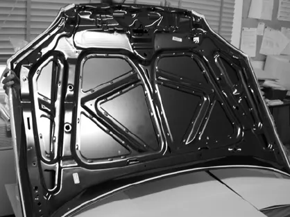
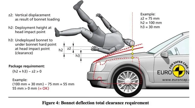
Concerns regarding the severity of a potential pedestrian head injury during a collision with a motor vehicle have led to advanced hood designs on many models. Such designs may include a multi-cone inner hood panel design. An active structure that is capable of pushing the surface of the hood away from the vehicle's hard motor components in the event of a pedestrian crash is also in use. Pyrotechnic or spring force designs are often used in the active-hood design.
- The opening angle of the hood
- N CAP Crash Test
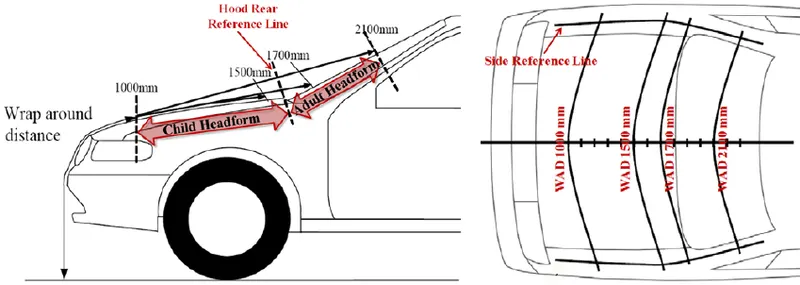
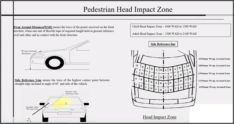
- Wrap Around Distance (WAD)
- NVH (Noise, Vibration, Harshness)
Opening Angle of Hood:
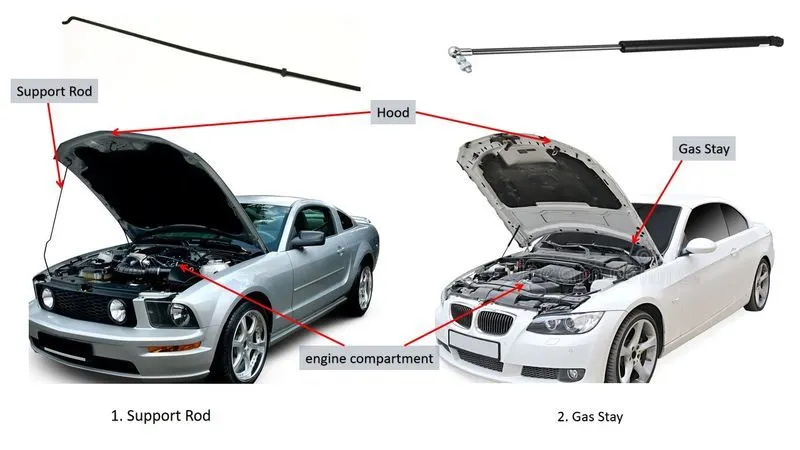
This is one of the main criteria in designing the hood. The opening angle varies from country to country. For example, the average height of the Indians is 5.8 feet whereas in the European countries the average height will be 6 feet, based on these heights the opening angle may vary. The opening angle is considered important because when the opening angle is less there is a chance of head injury to the person opening the hood. The hood need supports to set an open angle according to the average height of people in different countries. There are two types of supports to hold the hood.
- Support Rod
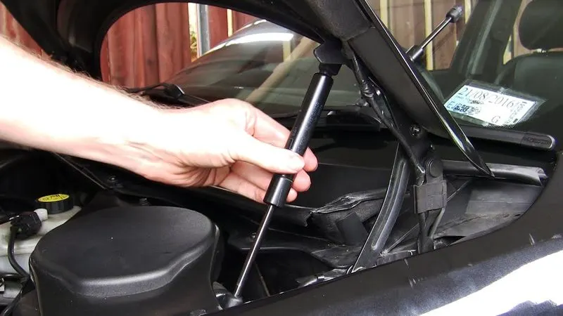
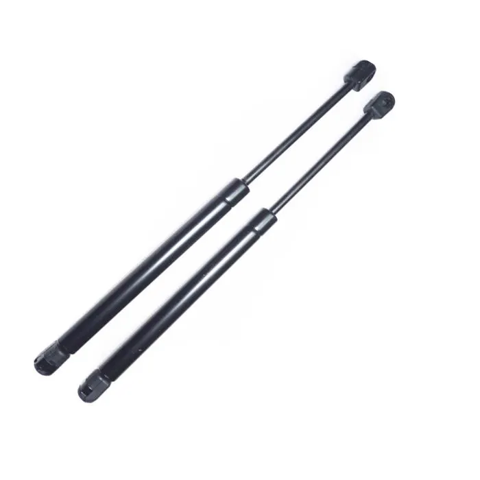
- Gas Stay
Support Rod:
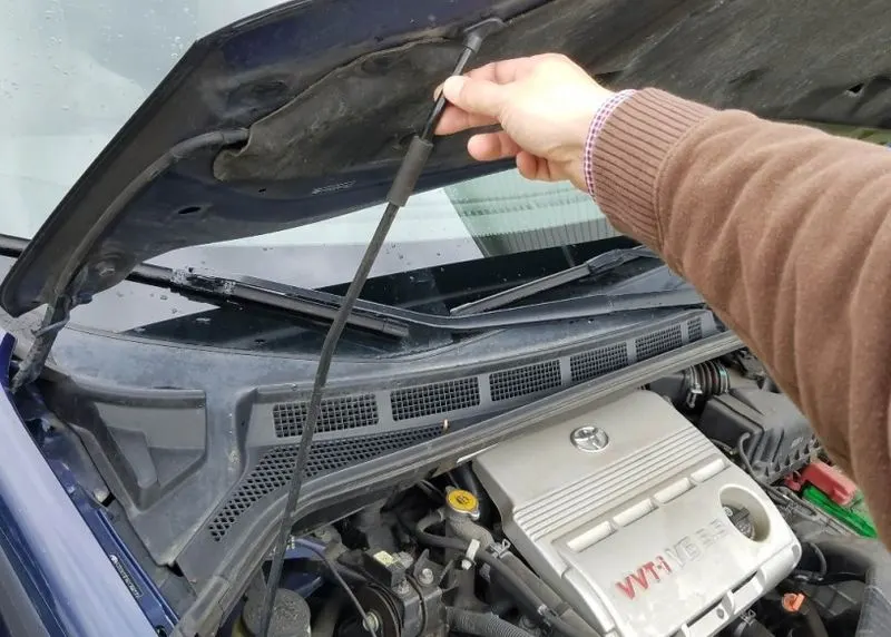
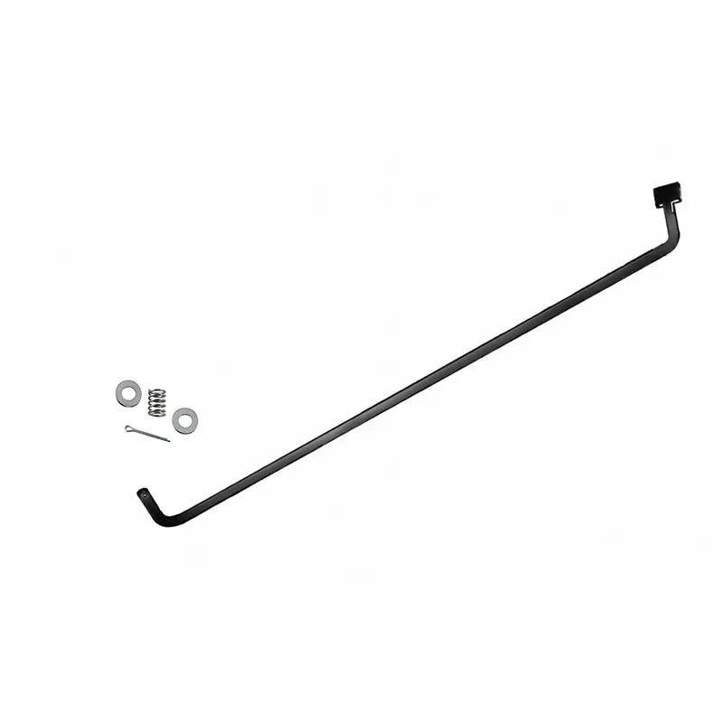
The support rod is quite simple in design and cheap in cost. This is widely used in many low-budget cars. In this type, we have to lift the hood by ourselves and place the support rod in the space provided in the hood or engine compartment. In the support rod, a small bend needs to provide in the rod to strengthen the support rod. We need to consider that the battery must be fixed in the engine compartment before providing space for the support rod. if we do not consider this then we won't be able to access the battery part, because the rod will be obstructing the path.
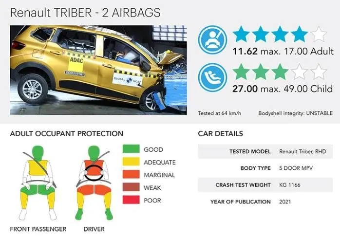
- The child and adult head impactor test will be considered for the regulation.
- Test area for child head impactor: 1,000mm ≤ WAD ≤ 1,700mm
- Test area for adult head impactor: 1,700mm ≤WAD ≤ 2,100mm
- Child head impactor: Diameter 165mm, weight 3.5kg
- Adult head impactor: Diameter 165mm, weight 4.5kg.
- Blanking and Piercing
- Deep Drawing
- Embossing
- Hemming
BLANKING AND PIERCING:
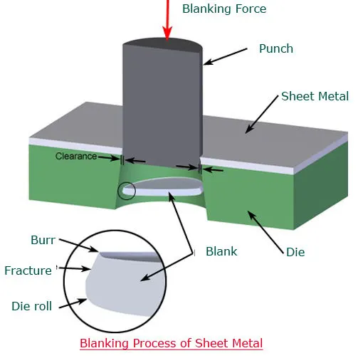
In Blanking, Piercing, and sharing processes a punch and die are used to modify webs. The tooling and process are between the two are the same, only the terminology is different. In blanking the punched-out piece is used and called blank whereas in piercing the punched-out piece is scrap. The process for parts manufactured simultaneously with both techniques is often termed pierce and blank, an alternative to piercing is punching
Purpose:
- Reduce bodyweight.
- Improve the strength of the body.
- Improve Mileage of car.
- Distribute impact force.
DEEP DRAWING:
Deep drawing of sheet metal is used to form objects with dept. it is plastic deformation in which a flat sheet metal or plate is formed into a recessed three-dimension part with a depth several times the thickness of the metal. The process of deep drain begins with a flat sheet metal held on the upper surface of the die. It is used in manufacturing inner panels. The material used is aluminum as it can absorb twice the crash energy of mild steel. Lighter dent-free and make body panels thicker while still lowering weight.
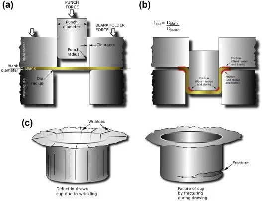
Purpose:
Operation in which thickness of the shell wall is reduced and its surface smooth. When the material gets compress between punch and die, which reduces the thickness and increases the height of the cup.
EMBOSSING:
Sheet metal embossing s is a stamping process for producing raised or sunken designs or relief in sheet metal. This process can be made by means of matched male and female roller dies or bypassing sheet or a strip of metal between rolls of the desired pattern. . It s-is done by pressing a sheet of paper into the female die, that has a design attached to it. This is usually done with a male counterpart underneath the paper so that the two and design are transferred to the paper.
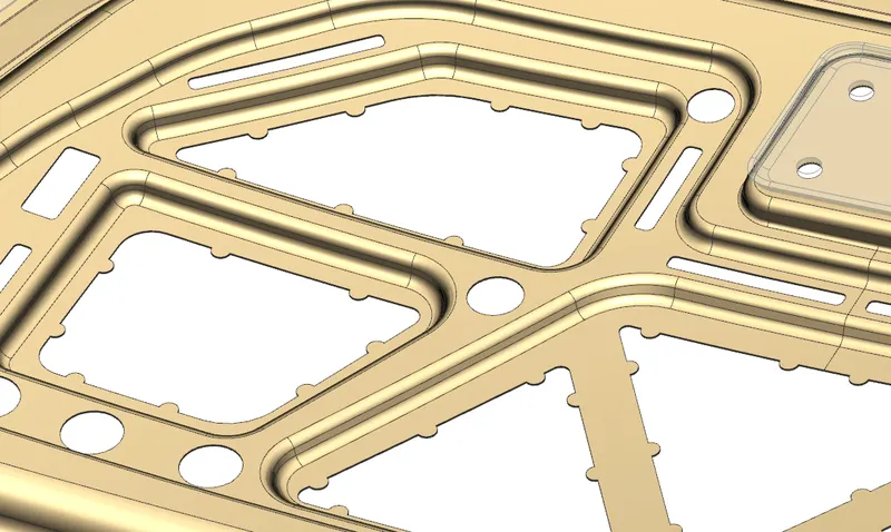
Purpose: Embossing enables you to highlights important elements of your printed products, such as letters (Company name) and designs ( corporate logo), to make sure they stand out. Embossing can also be combined with foil stamping to help create the effect of 3D images on printed paper that really shines.
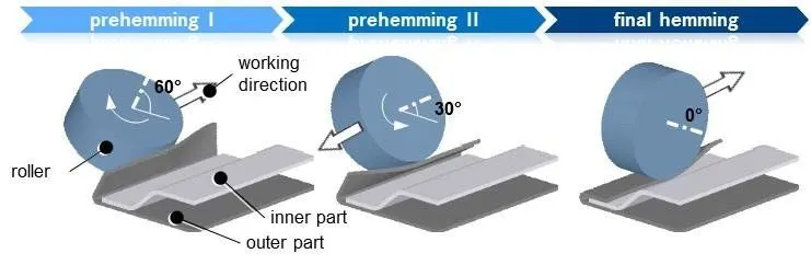
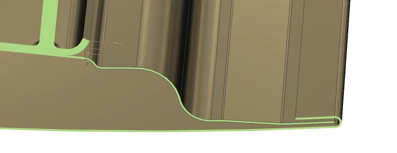
HEMMING:
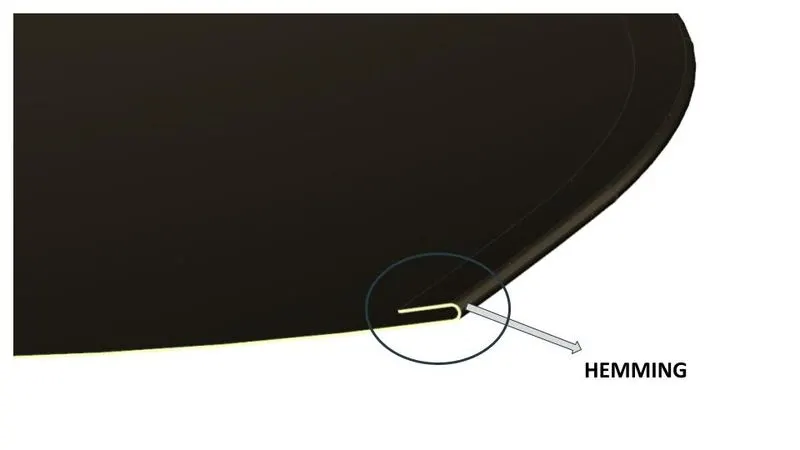
Hemming is a sheet metal forming process in which sheets are joined by bending them to 180degree. Automotive body panels and automotive parts such as decks-lids, trunk-lids, doors, hoods, and tailgates are formed by the hemming process, in this process usually, a sheet is bent with the help of the inner and outer sheet.
Designing of the Hood using NX software
Input Data
1. Outer hood panel thickness=0.75 mm
2. Inner hood panel thickness=0.75 mm
3. Reinforcement thickness=1.5 mm
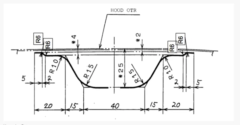
Master sketch
HOOD OUTER PANNEL
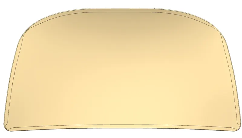
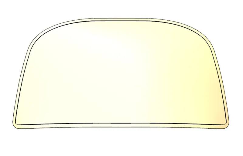
Outer panel is nothing but a outer skin of inner panel. Otherwise called as a cover of inner panel. It is the part. which gives luxurious look to the hood or bonnet. Outer pannel and inner panel cannot join by any welding process like spot welding or rivet, which spoil the outer look of a car.
Design of Outer Panel:
The given Class A surface has been used to create the outer panel. It is then trimmed into half using the XY plane.
The outer surface is offset to a distance of 0.5mm and the sharp edge is filleted to a radius of 30mm and the main panel is split with the offset created. Then the outer edge is swept using Law extension and the offset is created for the Sweept model at a distance of 20mm.
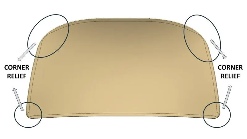
An offset is created with the main panel at a distance if 3.25mm and the inner surface if the panel is trimmed with the offset.Then considering all the top panel,offset panel and the Law extension an edge blend using the three surfaces is created. This is the hem that is required to create in the panel. Inorder to give reliefs in the front and right of the panel draw splines using G1 continuity on the front and back side of the hem.
After trim the surface using the created lines. Mirror the obtained panel using Mirror geometry and Sew the surface.
HOOD INNER PANNEL
This study introduces a new method for decreasing the hood stiffness, by making a hole on the inner hood panel. To determine the most effective hole position on the inner hood panel, the method of modal stiffness was employed, in an attempt to reduce the HIC from a collision between a vehicle and a head-form impactor. FRF (frequency response function) results for the reference vehicle model on head-form impact simulation were obtained. In addition, modal analysis of the entire vehicle model was simultaneously carried out. Subsequently. using the results of these two analyses, dominant frequencies (41.7 Hz and 83.3 Hz) were obtained, which related to deformation of the inner hood panel. Then, adequate hole positions at each modal frequency were selected, and the inner hood panel was improved, by making a hole at these positions. Finally, through head-form impact simulations on the improved vehicle model with the hole, it was demonstrated that the new method applied in this study is acceptable and useful. In the case of the improved vehicle model with a 40 mm diameter hole on the inner hood panel, this showed a significant reduction in the HIC of approximately 12.2%, compared to the original vehicle model.
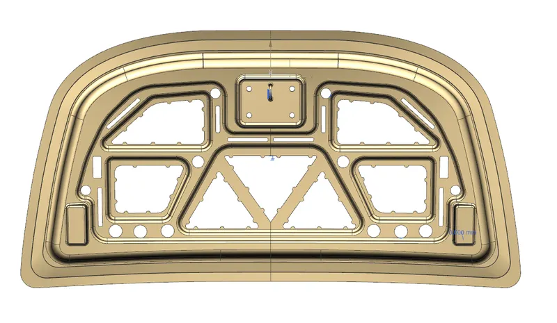
Designing of model:
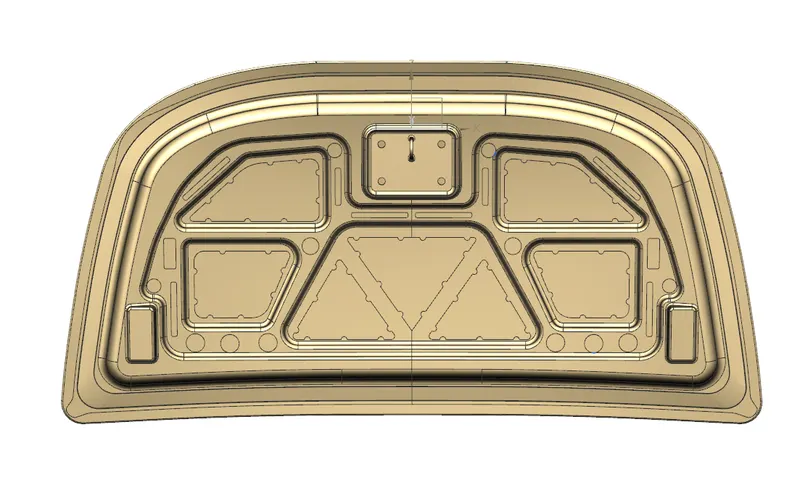
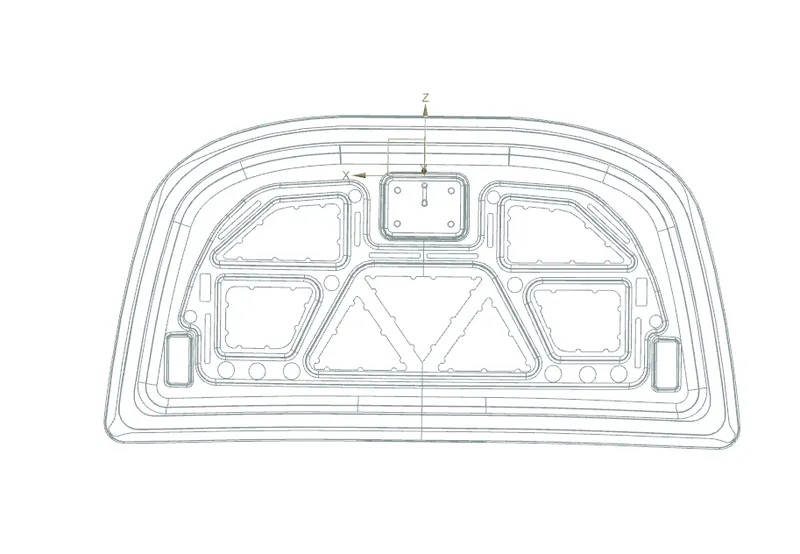
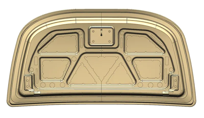
The inner panel is designd using the given Class A Surface. Trim the Surface using the XY plane.
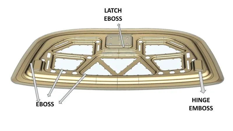
Offset the Surface to 2mm,4mm and 25mm and create offset to the boundaries at distance of 20mm on first offset 22mm and 35mm on second offset,50mm on the third offset respectively.Trim the sheet as per the offset and discard the material from the sheet as required. Then use through surface and join the three sheets as required and then use edge blend to give fillet to the edges of the surfaces. Allow pace for latch and Hinges and then create a profile to create an emboss on the surface.On this emboss create separate profiles and emboss them also to a distance of 7mm.
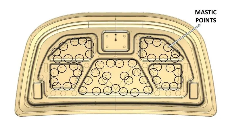
Create individual profiles on these profiles and also emboss them. In these emboss create profiles allowing places of the mastric points such that the mastric points are given at these places and then trim these profiles from the obtained emboss sheet.These profiles are mainly added for weight reduction of the hood and also for reducing the head impact.
In the left over pace at the bottom left corner create a plane at an angle of the orientation of the panel and then then a profile is drawn on the plane for adjusting the hinge on the panel and it is embossed from the plane to get a straight emboss. Then the panel is mirrored using mirror geometry and it is then sewed together to get a single panel.
Latch trajectory
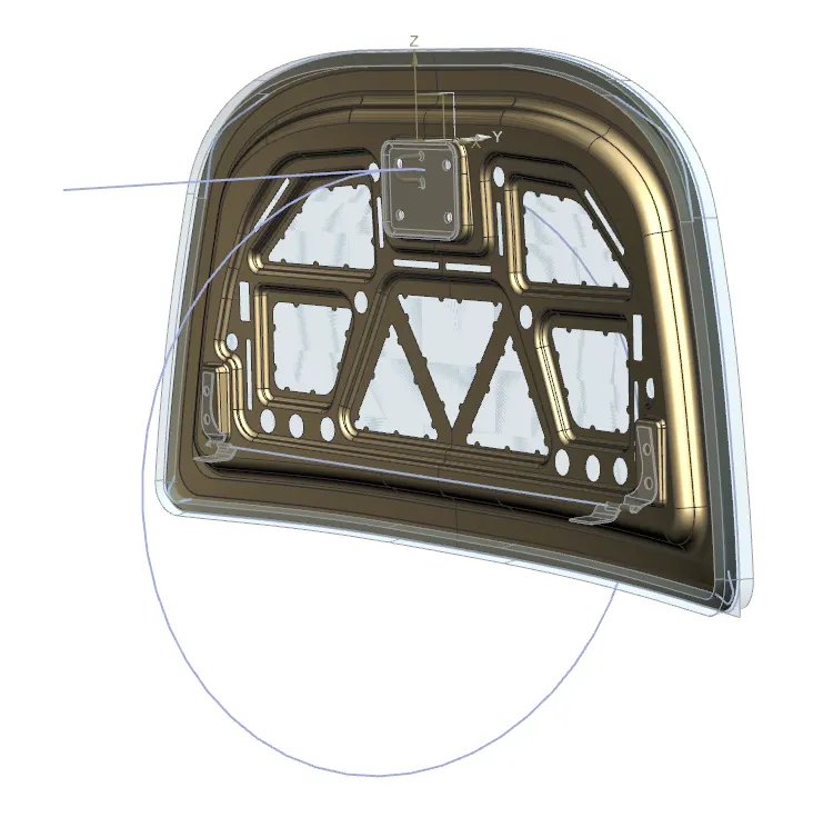
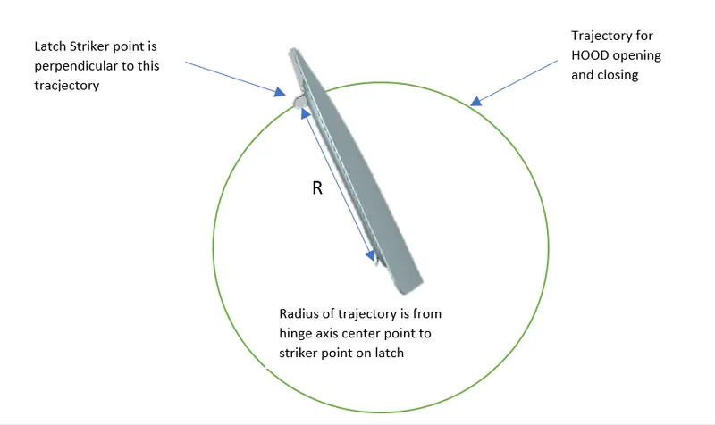
While assembling the latch with the hood panel it is strictly recommended that the position of latch striker should be placed such that the latch striker exactly fit into the lock hole in the engine compartment. Keeping this in mind, the latch striker is placed on the inner hood panel using latch trajectory path. This path is created using the the hinge axis taken as reference to draw a big trajectory path.
MASTICS
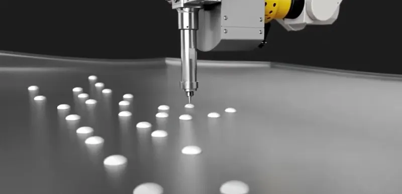
The main purpose of the outer panel is for aesthetic looks. Thus we cannot use bolts or welding. this has to be done with the help of hemming and mastic sealants. Mastic sealants are elastic compounds that behaves like the rubber. It is placed between the outer and inner panels. Initially it is in paste form t-but after the hot furnace bath, it will get hardened thus joining the outer panel and inner panel, Mastic sealants has the tendency to increase the strength of the panel and has the tendency to increase the strength of the panel and has the influence of 80mm diameter. Usually in designing these are created in inner panel using sketches and projecting them on panel. Later trimming of the sheet and blending it.
Draft analysis
In Siemen NX is one of the tool used to study the deep drawing feasibility easily through checking draft angle in the various faces.The Designer should Define a tooling direction in-order to check the draft angles For my design (inner panel), I have done draft analysis by defining a tool direction which is perpendicular to the plane created using the corner points of the model.
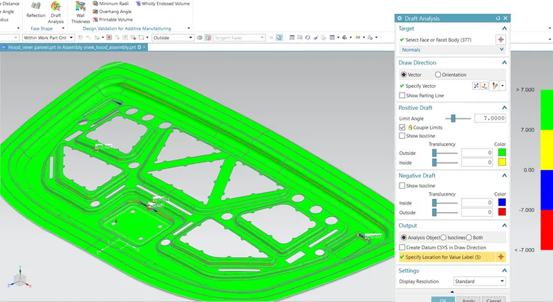
From the above picture , we can notice that there are some negative drafts.
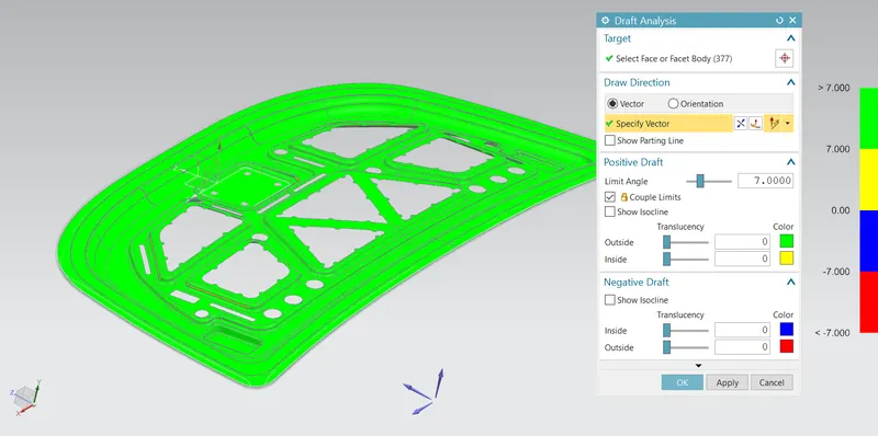
So to overcome this I have increased the draft angle of the the embose. in the picture below we can notice that the negative draft is cleared.
COMMANEDS USED:
- EXTRACT GEOMETRY:
creates associative copies of bodies faces, curves, points and datums and associative mirrored copies of bodies, within the same part
- TRIM SHEET:
Trims off a portion of a sheet body.
- OFFSET SURFACE:
creates a body by offsetting a set of faces.
- OFFSET CURVE IN FACES:
offsets curves along the faces on which they lie.
- THROUGH CURVES:
Creates a body through multiple sections where the shape changes to passthrough each section.
- LAW EXTENSION:
Creates a law controlled extension from a base sheet, dynamically of based on laws for distance and angle.
- FACE BLEND:
Adds tangent blend faces between selected sets of faces. The blend shape can be circular, conic or law controlled.
- TRIM AND EXTEND:
Trim or extends a set of edges or faces to the intersection with another set of edges or faces.
- EDGE BLEND:
Rounds sharp edges between faces. The radius can be constant or viable,
- PROJECT CURVE:
Projects curves, edges or points onto faces or planes.
- EMBOSS:
Modifies a body with faces made by projecting a section along a vector with options for end cap location and shape.
- MIRROR GEOMETRY:
Copies geometries and mirrors them across a plane.
- EXTEND SHEET:
Extends a sheet body by distance or to the intersection with another body.
- SEW:
Combines sheet bodies by sewing common edges together or combines solidies by sewing common faces.
- THICKEN:
Creates a solid body by adding thickness to a set of faces. WAVE GEOMETRY LINKER: Copies geometry for other parts in the assembly into the work part.
- DRAFT ANALYSIS:
Draft analysis is carried out to see that the panel can be drawn or not. It also helps to find the negative draft present in the component which can cause difficulty in manufacturability. FORCE
Final assembled images

CONCLUSION
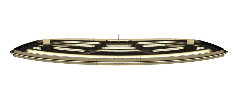
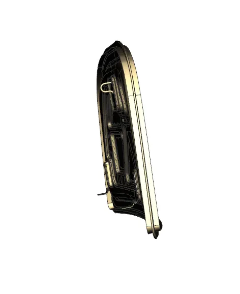
The complete assembly of the hood outer and hood inner panel was designed as per requirement. The latch and the hinges were also placed at appropriate position by following a latch trajectory strategy.