Hood design-Week 2
HOOD ASSEMBLY
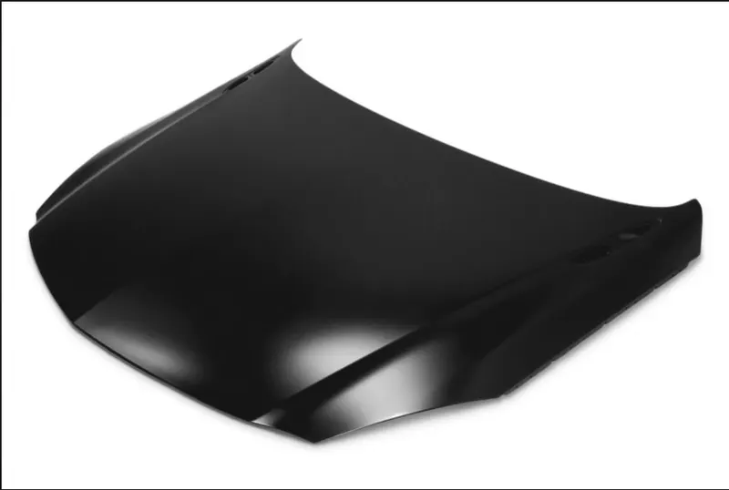
A car hood, also referred to as a bonnet in some other countries, is the hinged cover that rests over the engine of a front-engine vehicle.
Its purpose is to provide access to the engine for repair and maintenance. A concealed latch is typically used to hold down the hood.
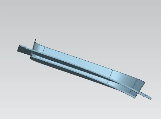
Hood assembly have Hood Outer panel , Hood inner panel , Hinge assembly and Stricker.
The hood outer panel is the outermost layer that protects the Inner panel and other things.
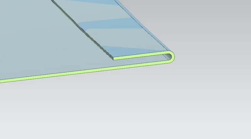
Both the inner panel and the outer panel are hemmed together.
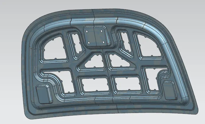
The inner panel have the emboss and the slots .
The slots are given to reduce the weight of the hood , while reducing the weight the hood may lose its strength thats why we are creating emboss on the inner panel.
The gaps between those emboss disipates the energy through the car body.
Here we are creating the Mastic point areas , these are the areas where the mastic glue is placed .
When heated the mastic glue spreads to about 80 mm .
The Mastic points is also helpful in reducing the Noise vibration and heat that is created while driving.
The hemming of the two panles are done with the series of rollers.
Hinge assembly is used to regulate the opening and closing of Hood.
Stricker is used to lock the hood with the engine compartment.
Most of the hoods are slightly curved in nature because it is of high strength then the staighten one.
Reinforcement on a hood gives better stiffness and impact strength.
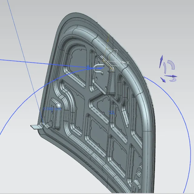
Latch trajectory is a Circle drawn from the centre point of two hinge axis that denotes the path of the latch and stricker attachment .
HEMMING-Hemming is a technology used in the automotive industry to join inner and outer panels together. It is the process of bending/folding the flange of the outer panel over the inner one.
DEEP DRAWING-Deep drawing is a sheet metal forming process in which a sheet metal blank is radially drawn into a forming die by the mechanical action of a punch.
It is thus a shape transformation process with material retention. The process is considered "deep" drawing when the depth of the drawn part exceeds its diameter.
OBJECTIVE:
To create a part body with the use of given sketch ,input surface and the given procedure using NX CAD.
TOOLS REQUIRED:
- wave Geometry Linker - Creates the exact copy of the body or face .
- Offset Surface - Moving the exact surface to the required distance.
- Offset Curve on Face - The selected curve moved to a required distance.
- Trim sheet - Trim the sheet using the tool( curve or face).
- Through Curves- Using this two surfaces are joined by using a boundry.
- Law Extension- Flanges or seperate surfaces are created with the use of edges or curves.
- Emboss - Creates a projection on the surface with the use of given sketch.
- Face Blends - Blends two faces by giving a radius.
- Edge Radius- Blend the sharp edge with respect to the radius.
- Mirror- Create the exact shape of a feature on the other side by specifying a centre plane.
- Extend Sheet - Extend the sheet by specifying the edges.
- Sew - Join two surfaces.
- Thicken - Thickens the component as per the dimension in the respective direction
- Trim and Extend - Trims the sheet with the use of a tool.
- Edit Section- This helps to see the sectional view with respect to the plane.
- Untrim - The sheet is converted to a original created form.
- Assembly Constraints - To arrest the degrees of freedom and assemble the parts.
DESCRIPTION:
Open a new assembly work bench.
Add the existing hood outer panel to that .
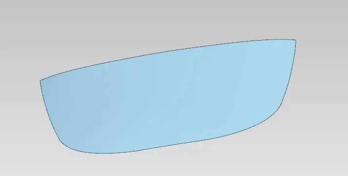
For the inner panel we have to work within the assembly.
so we have to create a new model within the assembly workbench and name it as Hood inner panel.
Using the wave geometry linker copy the body of the outer panel and paste it in the part navigator of hood inner panel.
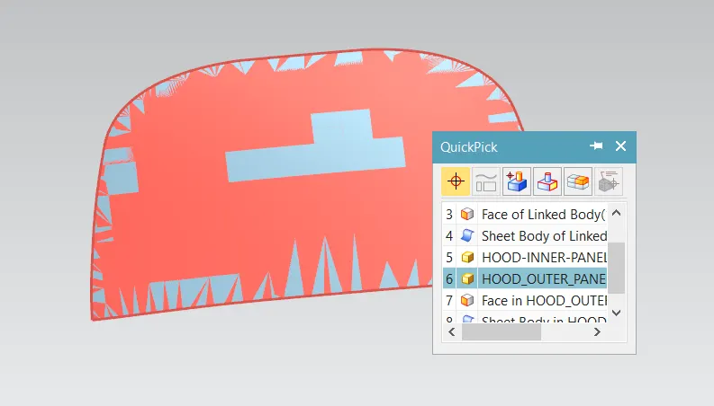
HOOD INNER PANEL:
First we have to work on hood inner panel.
We have to work inside the hood inner panel part navigator.
so hide the surfaces other than linked body of hood inner panel.
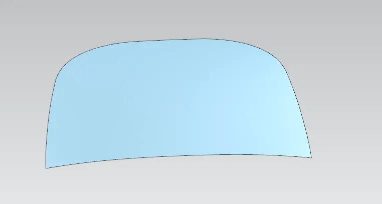
Offset the surface to about 0 mm and trim that surface with the use of YZ plane.
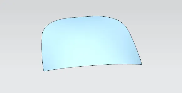
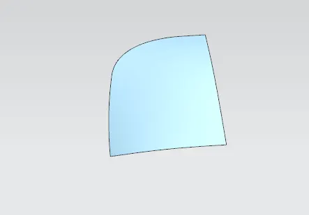
Offset the trim sheet again to 0mm and make it a feature group of working surface.
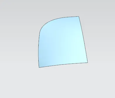
Offset the working surface for about 2mm. offset curve in face for about 20 mm as per mastersection. Trim the sheet using the curve.
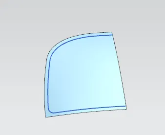
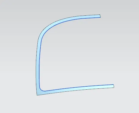
This is the first layer of inner panel.
Then again offset the working surface to about 4mm. Offset curve in face to about 22 mm by specifying the boundry. Trim the surface with the use of offseted curve.
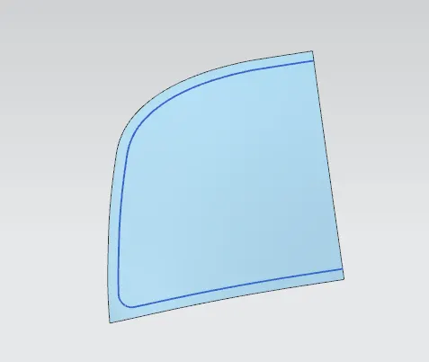
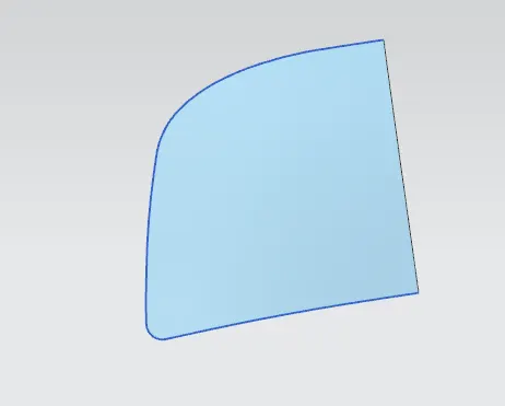
This is the second layer of the inner panel. Join the above two surfaces using through curves.
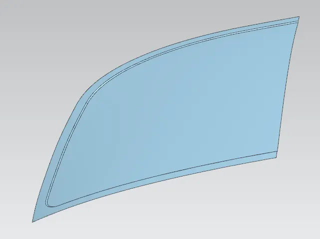
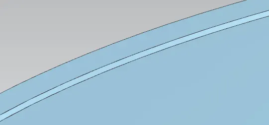
Offset the working surface again to about 25mm , the boundry is offseted using offset curve on face to about 50 mm and trim the sheet.
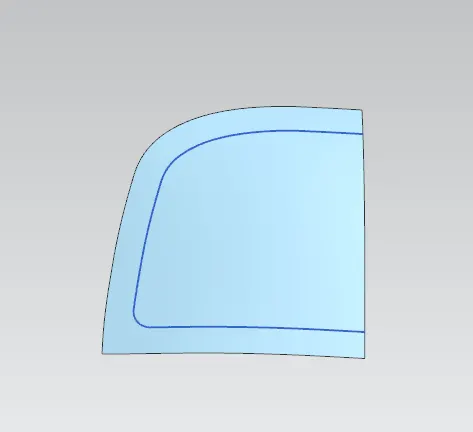
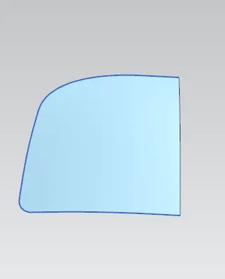
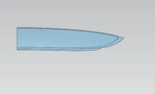
With the use of the same offset curve create a law extension on the edges and trim it with the second layer of Hood Inner panel.
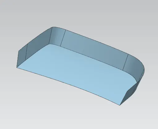
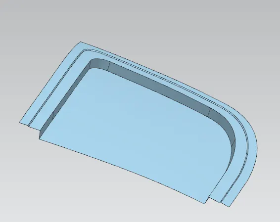
Join the First layer and the through curves with face blend at 6mm . Similarly join the Second layer with the Previously joined surface with face blend at 6mm.
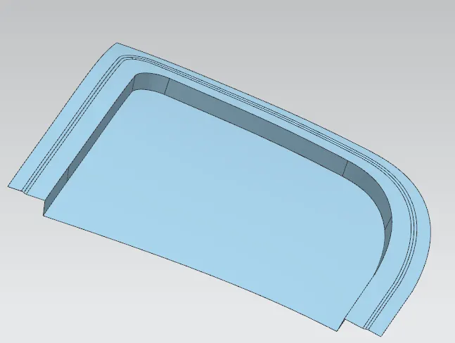
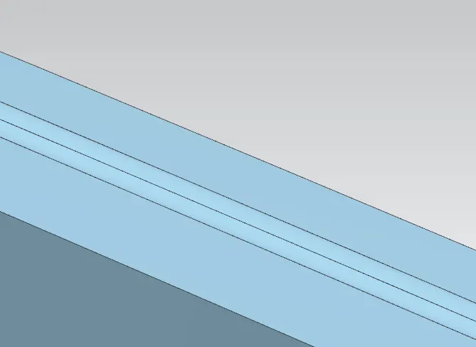
Join the third layer with the above surfaces with the face blend at about 15 mm.
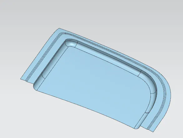
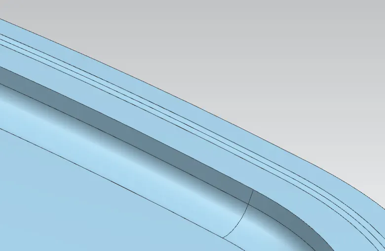
While trimming the law extension with second layer the faces are joined . so here we have to use edge blend at about the radius of 10 mm.
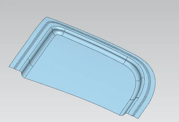
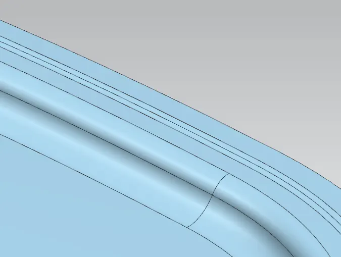
Next we have to create the emboss on the face of inner panel.
Offset the edges of the bottom surface to about 15 mm.
Create a sketch on ZX plane and project these curves and draw rectanles at pecific places for hinge and stricker placement emboss.
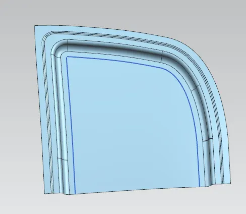
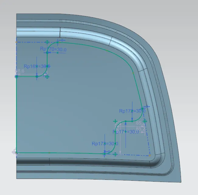
Again project the sketch to the surface and create the emboss with the emboss command.The edges are blended with the use of face blend at about 6 mm.
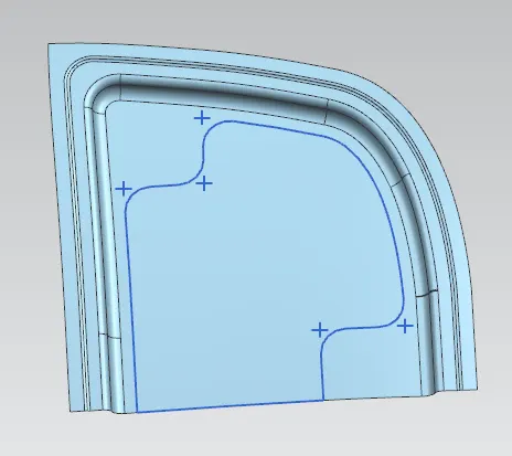
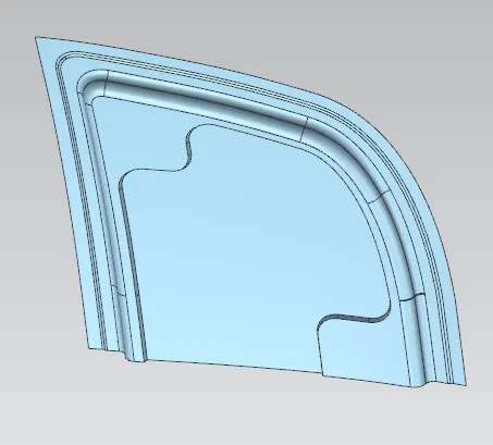
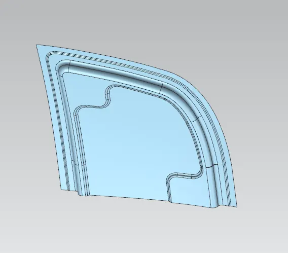
Again small emboss features are created with same procedure.
Offset curve of edges at the emboss created to about 15 mm. Create a sketch and project the offsetted curve on the ZX plane.
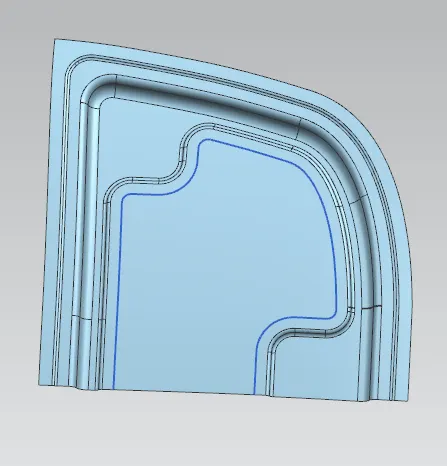
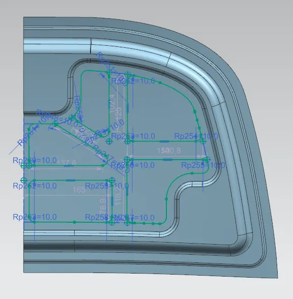
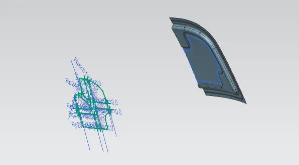
Draw required shapes and again project it on the surface.
Create emboss on the embossed surface.Blend the edges using edge blend
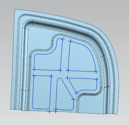
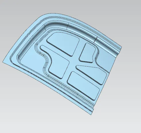
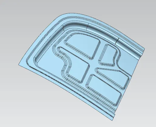
Now we have to create the areas for Mastic points.
Here we have to copy the sketch that is used to create the secondary emboss and alter it .
Offset all the curves for about 10 mm inside. Draw circles at respective places and trim the sketch for required shape..
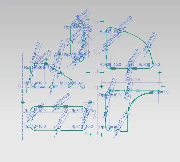
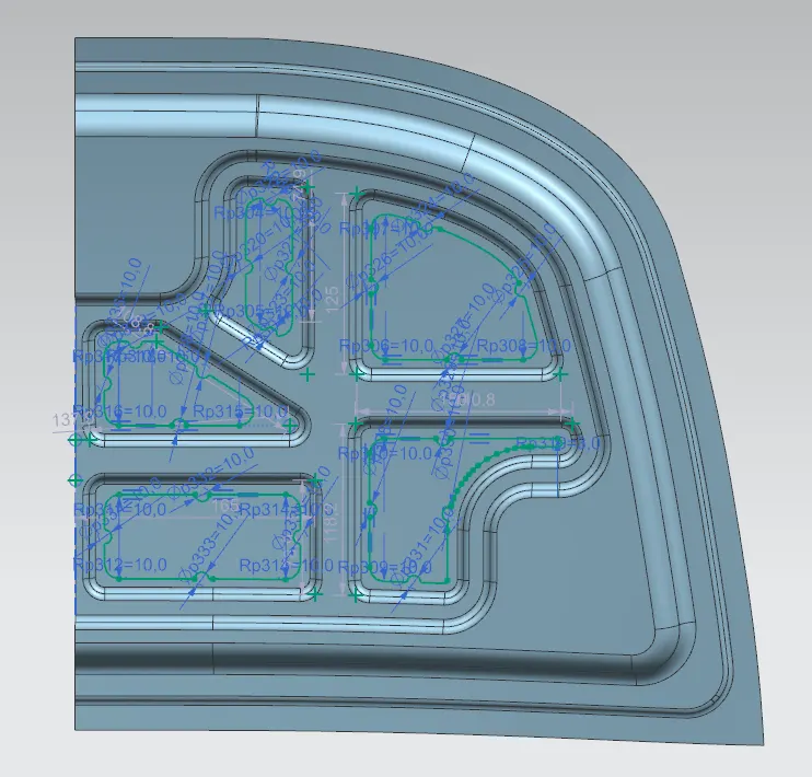
Project the sketch to the surface and trim the surface.
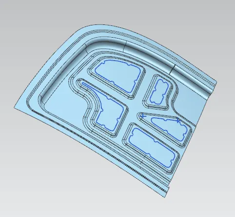
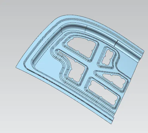
Offset the outer edge of first layer to about 2 mm and trim the sheet.
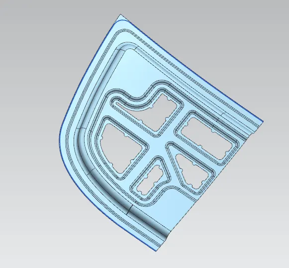
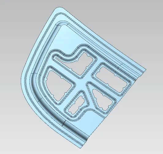
Extend the sheet and trim it with the YZ plane. This will helps in reducing the gap while sewing.
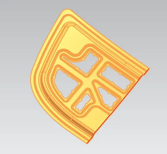
Create a emboss at the place of hinge assembly.For that we have to create a plane that is slightly tilted and looks parallel to the inner panel.

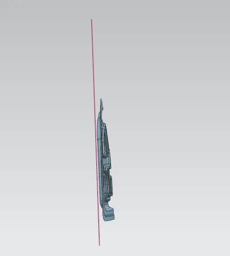
Create a sketch on the plane and using this sketch create a emboss.
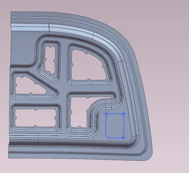
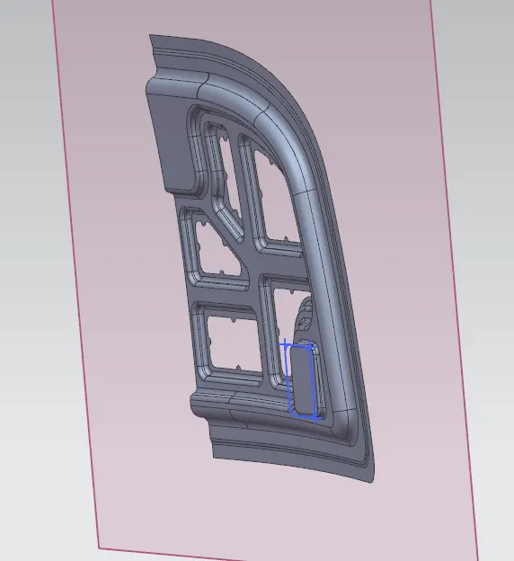
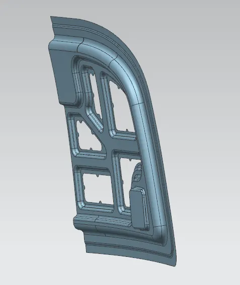
Create emboss at the sticker placement area .
Position the stricker infront of the assembly area and create a linked face with wave geometry linker inside the hood inner panel using the base of the stricker.
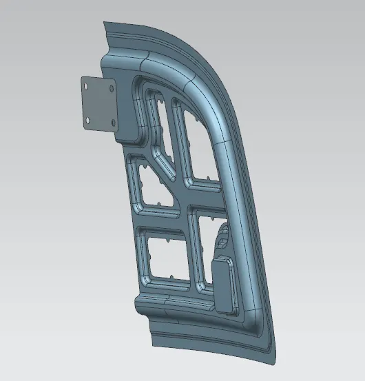
Trim the linked face with the YZ plane . Offset the boundry of the face using offset curve in face to outside at about 5mm.
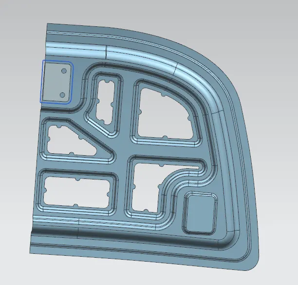
Untrim the trimmed sheet and use it as a face for the emboss.
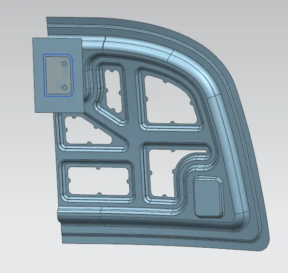
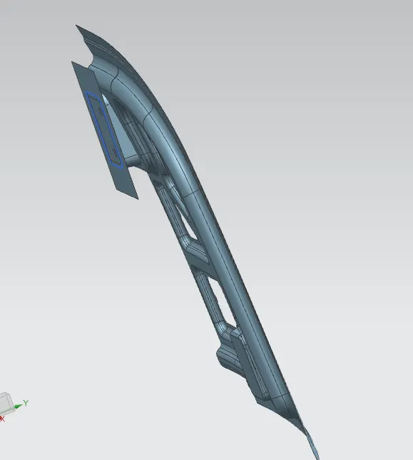
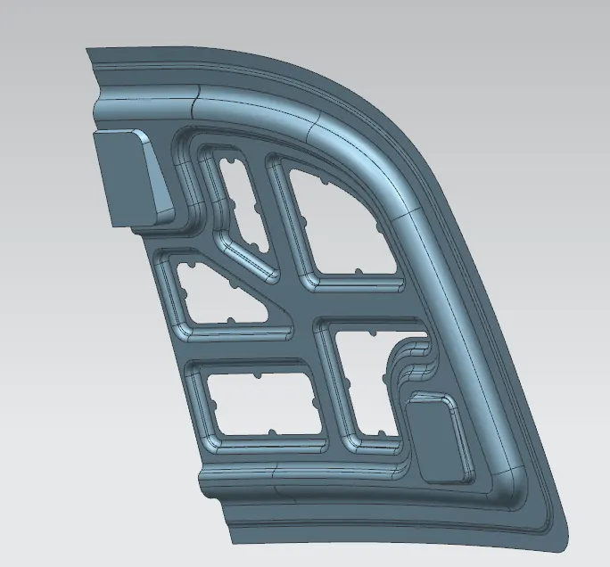
Extract the curves of the holes and trim the emboss using the hole.
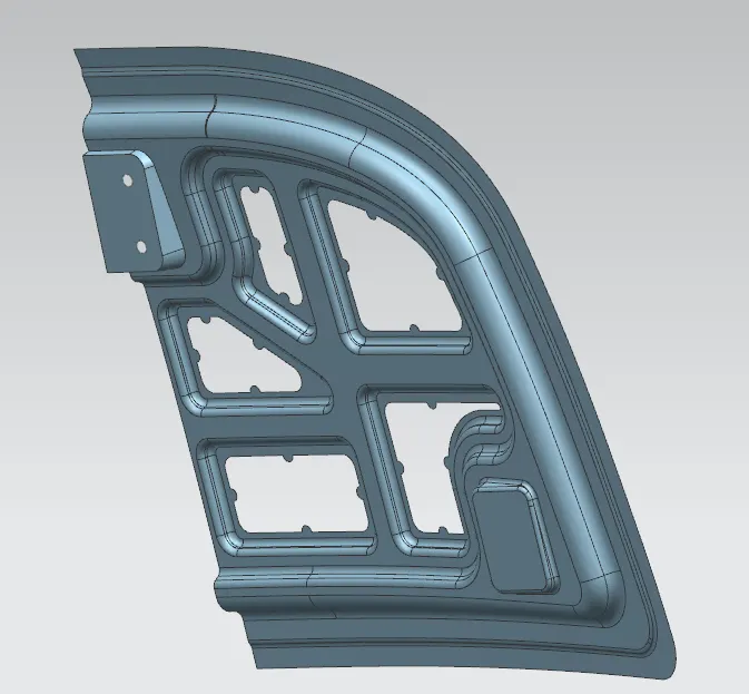
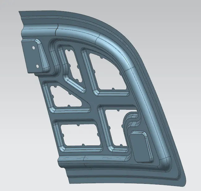
Mirror the sheet and sew it.
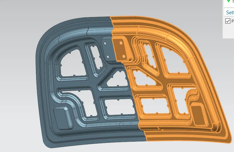
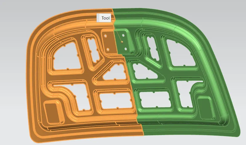
Thicken the sheet to about 0.75mm.
HOOD OUTER PANEL:
Next we have to work on Hood Outer Panel.
Already we have inserted the body that is skin data. so now we have to work on the part navigator of Hood outer panel.
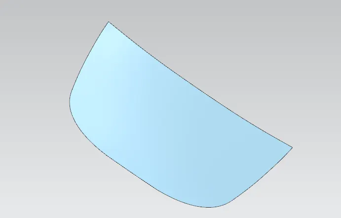
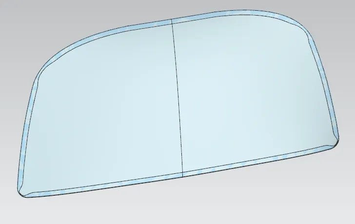
Offset the body to 0mm and trim it with the YZ plane.
Again offset the trim sheet to 0 mm and this is our working surface.
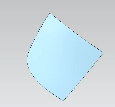
Offset the curve on the working surface for about 0.5mm.
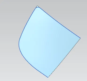
Create a surfave at about 80 deg using the law extension.
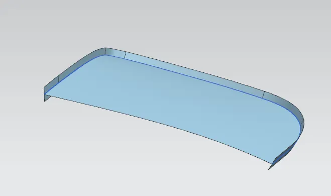
For the hemming we must have top, bottom and side surface so the working surface is offseted to about 2.95 mm .
Offset the law extension inside to about 15 mm.
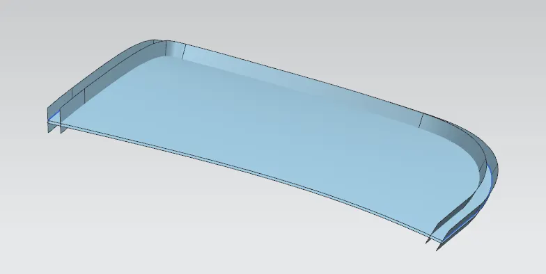
Trim the both offsets using trim and extend command.
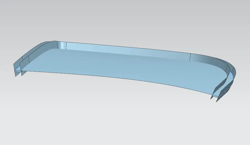
Using the face blend, blend the three surfaces .
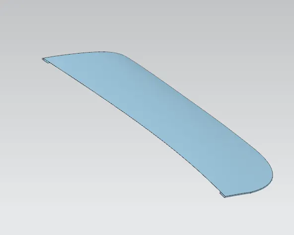
Create a releif at the edge using spline and trim it from the surface.
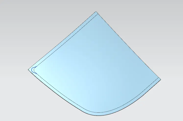
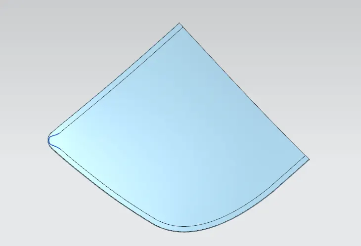
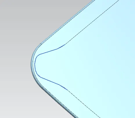
Create another clearance at the opposite side.
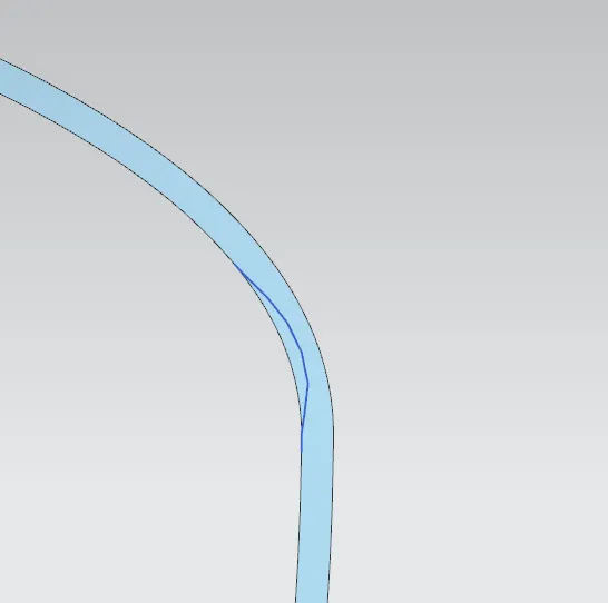
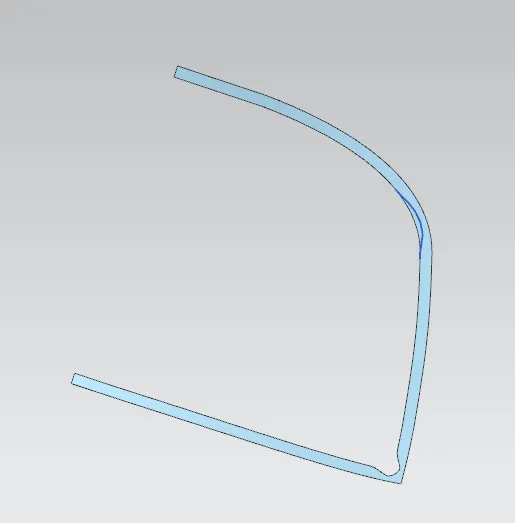
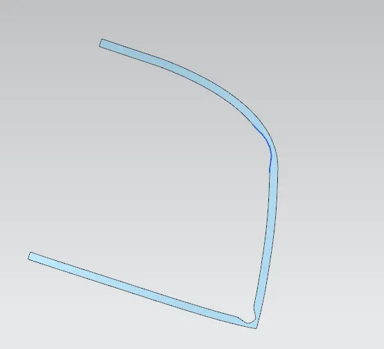
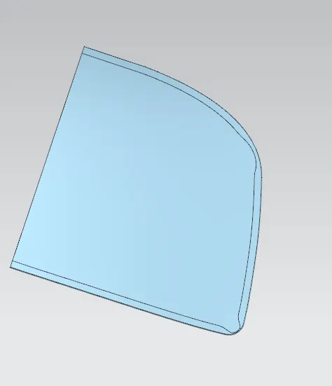
Mirror the surface and sew it .
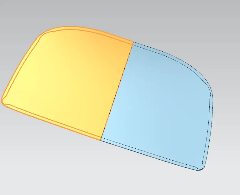
Thicken the part inside to about 0.75mm.
HINGE ASSEMBLY:
We have already added the hinge assembly and positioned before creating the emboss .
Now we have to constrain it.
First the centre axis of engine compartment side hinge in hinge assembly constrained parallel with the X axis.
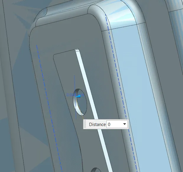
And constrain the two faces with the distance constrain at 0.
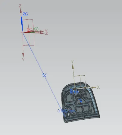
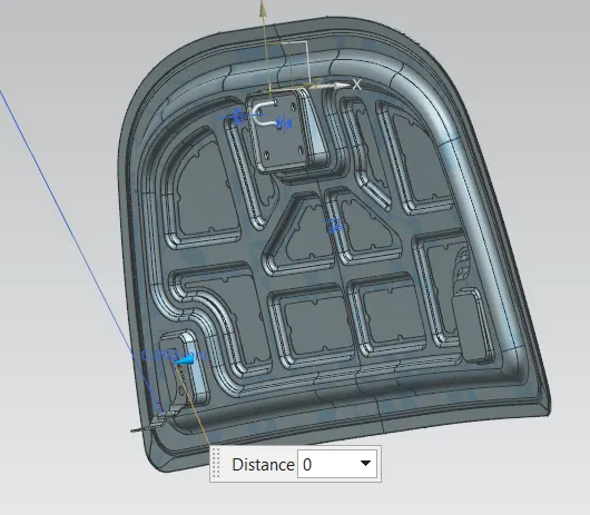
Mirror the hinge assembly using the mirror assembly.
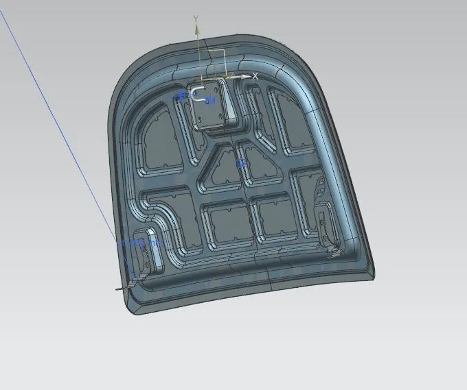
STRICKER ASSEMBLY:
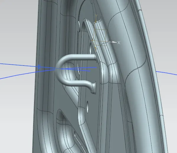
A line is drawn between two hinges by specifying the centre of the cylinder
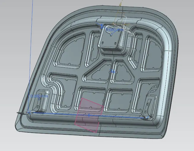
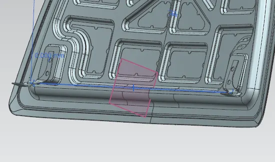
Create a sketch on the plane .
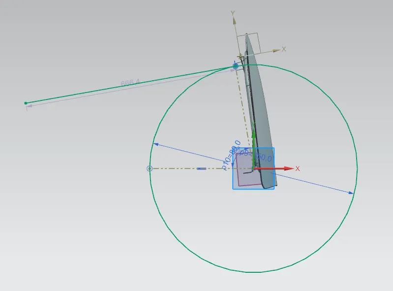
Create a Datum CSYS at the top edge of the stricker
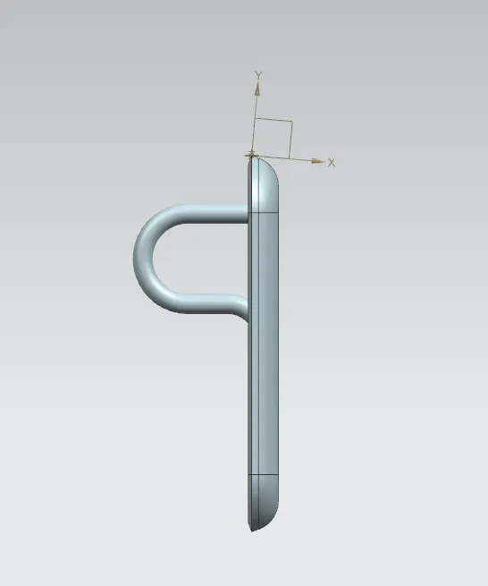
Create a sketch on the XY plane of the created CSYS.
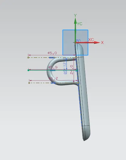
Now we have created two sketches so constrain the stricker using those sketches.
Constrain the lines of two sketches using prefer touch command.
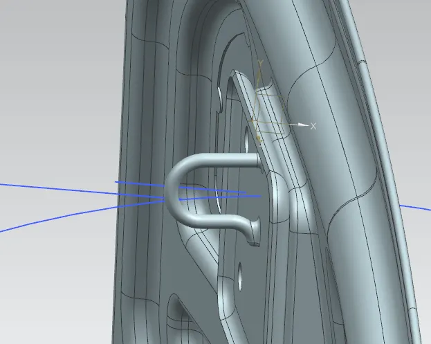
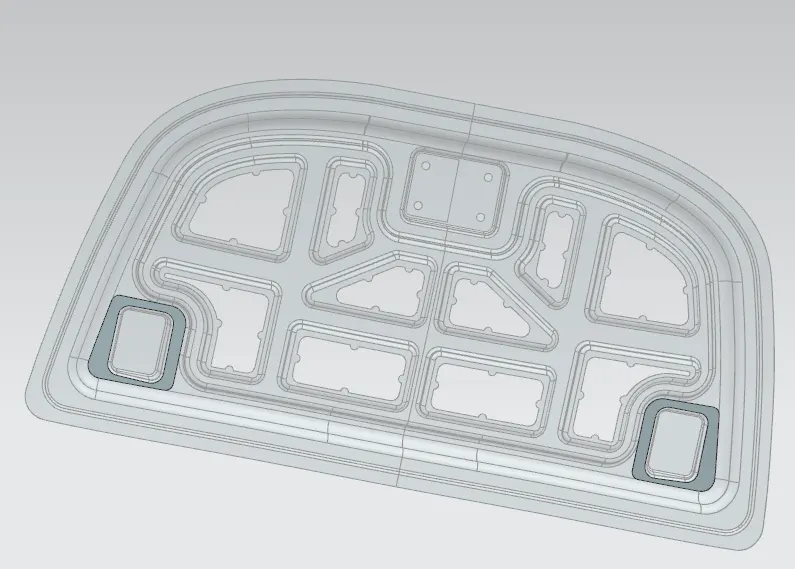
REINFORCEMENTS:
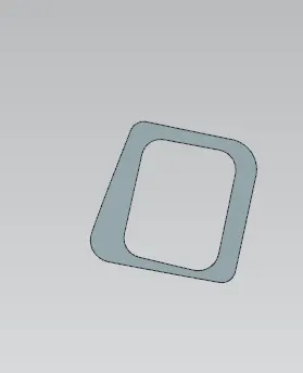
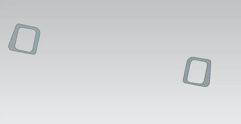
Create a new model inside the assembly for reinforcement.
Create a linked face using a wave geometry linker.
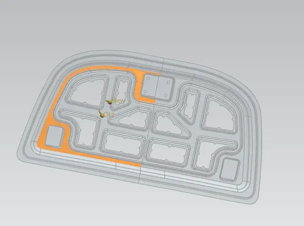
Trim them using a sketch.
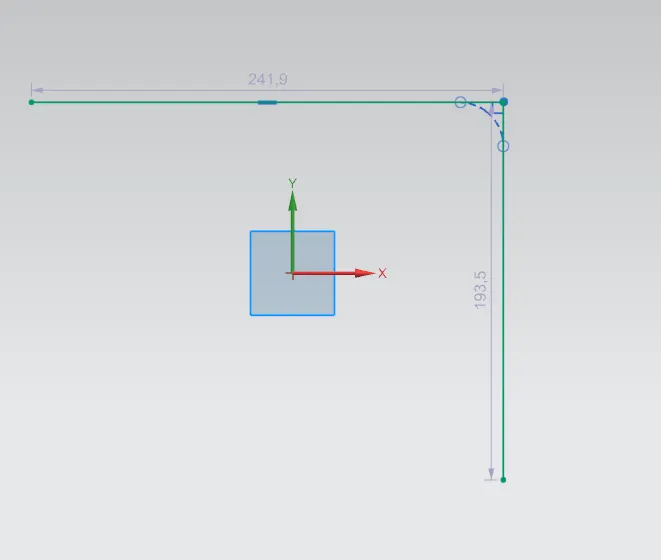
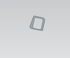
Thicken the part and mirror it.
CONCLUSION:
Thus the hood panels are created and assembled with the Hinge assembly and stricker using the given skin data and master section.