Hood design-Week 2
OBJECTIVE :
Design Hood Outer Panel, Inner Panel and the necessary reinforcements by following the Master Section mentioned with the Design parameters.
PROCEDURE FOLLOWED:
PREQUISITE KNOWLEGE FOR MAKING THE HOOD:
- DESIGN REQUIREMENTS FOR SAFETY OF THE PEDESTRIAN.
- DESIGN REQUIREMENTS FOR CALCULATED AND CONTROLLED DEFORMATION OF HOOD.
- DESIGN CONSIDERATION FOR STAMPING.
- DESIGN REQUIREMENTS FOR HEMMING.
- ADHESIVE AND SEALENTS
- LATCH TRAJECTORY
DETAILED EXPLANATION OF ABOVE MENTIONED PRE-REQUISITES:
- DESIGN REQUIREMENTS FOR SAFETY OF THE PEDESTRIAN:
When designing a car hood inner panel, the location of embosses for stiffning the hood should be carefully considered keeping in mind the location on the hood where the head of the adult/child is most probable to hit.
The following factors can be taken into account when deciding on the location of the cavity:
- Pedestrian impact zones: Research has shown that certain areas of a vehicle are more likely to cause severe injuries to pedestrians in the event of a collision. These areas are known as pedestrian impact zones. By removing the material of inner panel in a pedestrian impact zone, the impact force can be reduced, thus reducing the severity of injuries.
- Structural integrity: The location of the non material portion of the inner panel should also be considered in relation to the structural integrity of the hood. The non material portion should not compromise the strength and rigidity of the hood, as this could affect the safety of the occupants in the event of a collision.
- Manufacturing considerations: The distance of the embosses should also take into account manufacturing considerations, such as ease of production, tooling requirements, and material selection.
when pedestrian hit by the vehicle , it tries wrap around the body of the car, there are ample of possibility in the way one could hit the pedestrian but most prevelent consideration is the frontal impact.
The height of the dummy generally considered for testing of wrap around distance may vary depending upon the country where the vehicle is going to be used.
Wrap around distance :
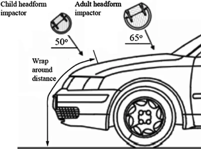
As mentioned earlier when pedestrian meet an accident the body tries to wrap around the bumper and the bonnet , the geodesic distance ( not the euclidean ) from refrence plane (or the ground plane) on which the four tyres of the vehicle lies till the position where the head is going to impact is called as Wrap Around Distance.
The point of imapct of head depends upon many factors such as the height of pedestrian being considered the bumper height, bonnet height and length, windscreen frame etc.
DUMMIES OR Anthropomorphic Test Devices (ATDs):
THESE ARE THE MANNEQUIN OF HUMAN WHICH ARE FITTED WITH DIFFRENT SENSOR AND ARE VERY SOPHISTICATED IN CONSTRUCTION SO THAT IT MEMIC THE HUMAN BEHEVIOUR AT THE TIME OF ACCIDENT. THESE DUMMIES HELP THE RESEARCHERS TO UNDERSTAND THE LEVEL OF IMPACT OF THE ACCIDENT ON THE HUMAN BODY.
Diffrent kind of dummies are used by testing agencies,example of some of the dummies used by euroNCAP are:
- Hybrid III: a family of dummies widely used in crash testing. They are used to represent adults and can be used for both front and side crash tests. They are not the most advanced but are versatile and have been used extensively all over the world.
- Hybrid III 50th percentile: The type of dummy placed in the front seats for Global NCAP's crash tests. They represent a 50th percentile adult male and weight 77.7kg without the instrumentation.
- Hybrid III 5th percentile (often called "Ms. Hybrid III"): Not used by Global NCAP. This is a smaller dummy that represents a short female adult. Similarly, the recent, more advanced THOR and worldSID dummies (for frontal and side impact respectively) are not used by Global NCAP yet.
- P-series dummies: An archaic child dummy that was used in Global NCAP's tests till 2017. These lack modern instrumentation and were developed at a time when there was an acute lack of data for development for child dummies.
- Q-series dummies: Relatively modern child dummies that have been used by Global NCAP since the 2017 revision. They are still far from perfect, due to a lack of anthropometry of children.
- Child dummies are specified using the series followed by the age the dummy is intended to represent, for example, Q3 means a Q-series dummy that represents a 3-year old.
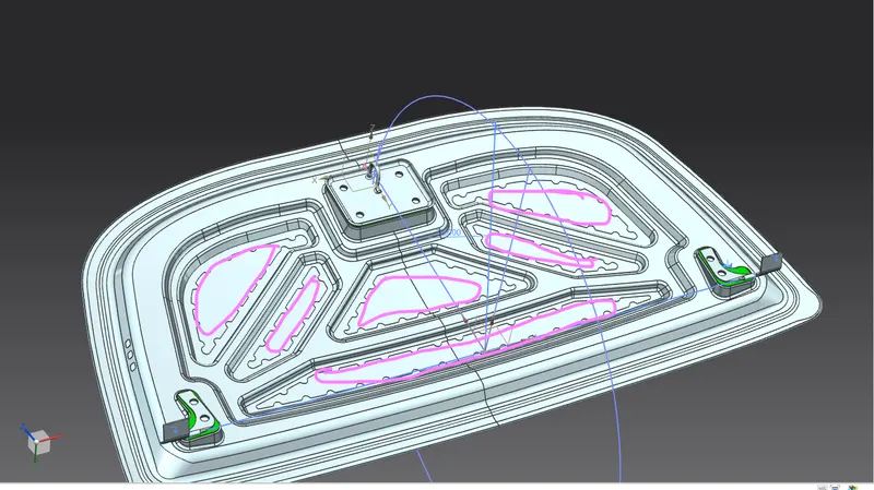
This figures heighlights the areas in pink which has been intentionally been cut out from the inner panel to provide some flexibility where the head is most probable to impact.At the same time some embsses are also created so that structural integirity is maintained.
2. DESIGN REQUIREMENTS FOR CALCULATED AND CONTROLLED DEFORMATION OF HOOD:
Previously the design intention of the vehicle was to make as robust as possible so that it will cause minimum monetry damage to the vehicle. The hood and bumpers and other periphery enclosers were made more stiffer. But after continuous research and evoution people started shifting their design intention from making the vehicle more stiff towards making it more safer.
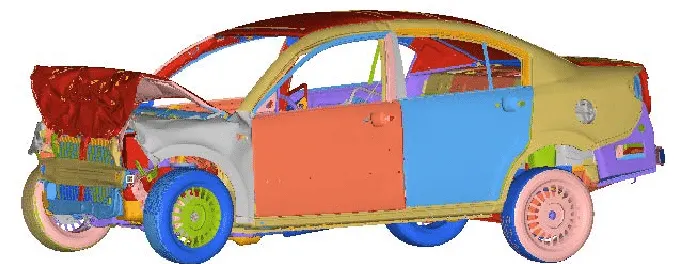
One very prevelant missconception people have in mind is that the material should very thick and non deformable to keep the occupant and the pedestrian safe. But instead the structure are made deformable so that it absorb some energy of the collision and cause less strain on the human body parts.
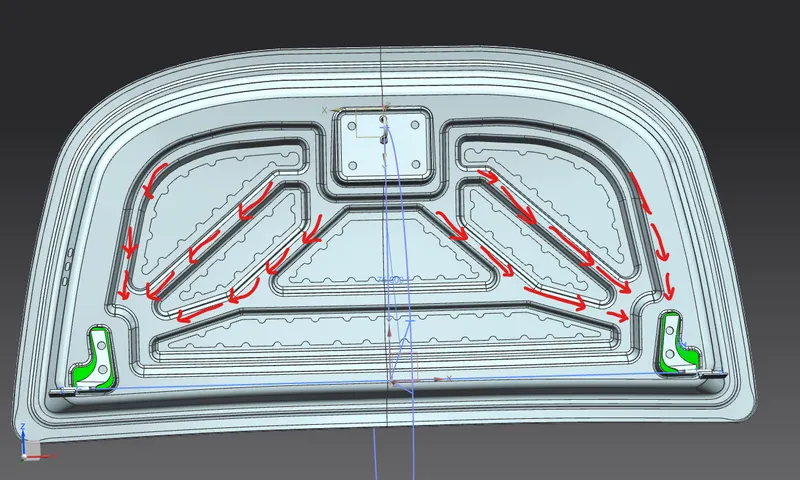
The structures are made in such a way that upon colision the force can be transfered toward the desired diection , as can be seen in the below example the force are transfered toward the hinges.
3. DESIGN CONSIDERATION FOR STAMPING:
1. Draft angle : Sufficent draft angle should be provided for stamping so that it can fulfill below purposes:
a. the part can be easily removed from the machine after stamping without any frictional hindrance.
b. the tool life will also be increased by doing so.
2. Avoid deep emboss: The embosses should be achieved in multiple stages , it should'nt be done in a single draw which may cause thining and tearing in the sheet.
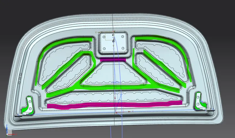
3. Give sufficient distance between two emboss: As it can be seen in the below image the area which has been highlighted by green there is suffucient distance provided between two stages of staping but the area which has been higlited by pink there is very less space provided between the two emboss which is not a good practice.
4. DESIGN REQUIREMENT FOR HEMMING:
1. The hemming flange should neither be too short nor be too long as making it more short will cause it difficut to apply the sealent and adhesive on otherhand making it too long will cause difficulties in bending it at the same time it will cause more material wastage.In the current challenge it has been asked to maintain the hemming flange to be 6mm which has been maintained.
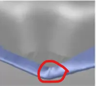
2. At the corner of the hemming flange some relief should be provided so that it will not cause the wrinkles (see image below ) and can facilatate the hemming effeciently.In the current challenge the width of flange at corner was given as 3mm so it has been maintained accordingly.
5. ADHESIVE AND SEALENTS:
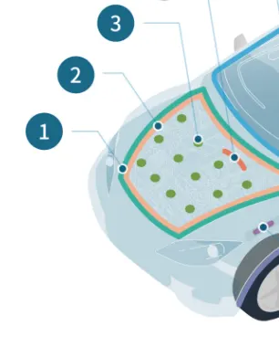
In the below figure:
1. Hemming Adhesive : The hemming are provided to avoid any kind of welding between between the class A surface and the inner panel.The hemming process requires the adhesive between the the two hwmmwd surface so as NVH issue and also give strength to the joining process.
2. Sealent : After hemming adhesive sealent is provided to avoide the entrance of moisture and water which can cause rusting.
3.MASTIC : Mastic is provided between the innner panel and the outer panel in the areas other than outer edges as their is no provision for hemming on those areas.
A gap of 5mm has been maintained between inner panel and outer panel for application of mastic.
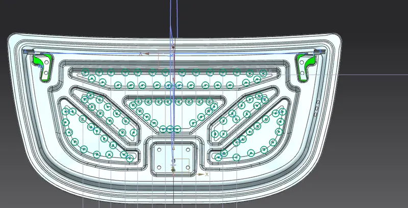
At the location of application of mastic area has been increased sufficeintly as ab seen in the below image:green circle depicts the mastic areas.
6. LATCH TRAJECTORY:
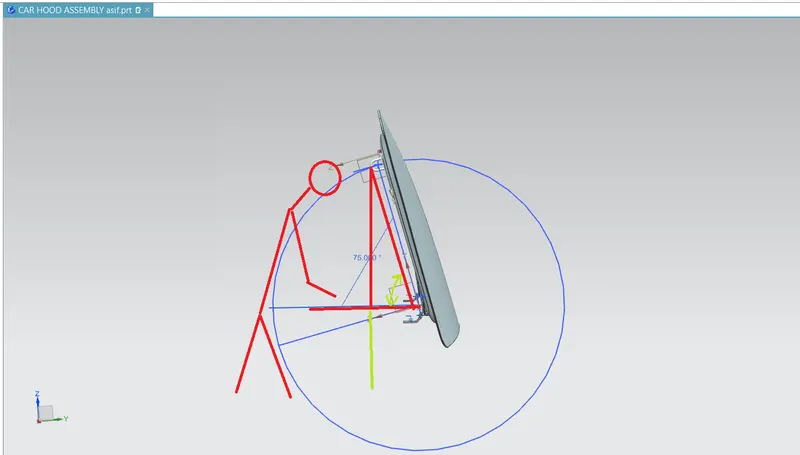
Latch trajectory is made to anlyse the opening angle required for easy and safe access to engine.
by making the trajectory we can calculate what should be angle of openinng of the hood so that it will not strike the human head when accessing the engine room.
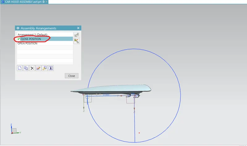
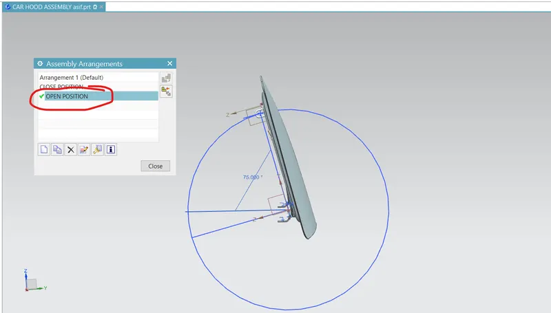
In the current challenge two ARRANGEMENT has been created to depict open and close position :
CLOSED POSITION (0 DEGREE):
OPEN POSITION (75 DEGREE):
FULLY FUNCTIONAL HOOD GIF:
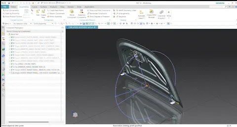
THE POSITION OF STRIKER HOOK TIP CAN BE CALCULATED BY SIMPLY APPLYING THE PYTHAGORAS THEOREM , AND HENCE WE CAN CONFIRM THE REQUIRED CLEARANE BETWEEN THE HEAD OF THE USER AND THE STRIKER TO AVOID INJURY.