Hood design-Week 2
Aim:Designing the Hood Outer Panel, Inner Panel and with the necessary reinforcements like emboss & hinges by following the Master Section with the Design parameters.
Objective: A detailed report about the Hood Design which includes a detailed explanation about hood and its components, Latch Trajectory, Mastic Data, Emboss Definitions, Manufacturing process like Deep-Drawing and Hemming, and all the parameters followed in the design.
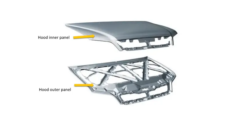
Img): point of view of hood
INTRODUCTION ABOUT HOOD:
The hood or bonnet is the hinged cover over the engine of motor vehicles. Hoods can open to allow access to the engine compartment, or trunk on rear-engine and some mid-engine vehicles for maintenance and repair. it contains the inner and outer panel, the inner panel provides the strength while the outer panel functions as metal cover.
It is the covering for engine in front engine vehicles, which protects the engine from sunlight and dust. It functions are-
1.Helps in aerodynamical flow.
2. Protects the passenger and pedestrian.
3. Reduces the air resistance
Hood consist of following major components:
1. Hood inner panel
2. Hood outer panel
3. Latch and Striker, Hinges.
4. Embosses and Reinforcemnts attachments.
Img): of hood
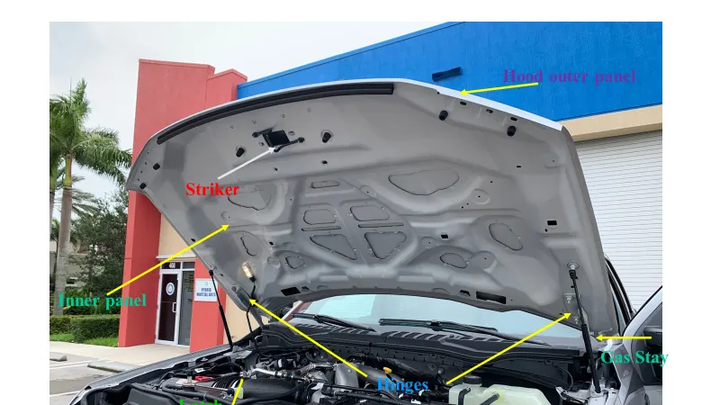
Major components of hood:
Inner panel:
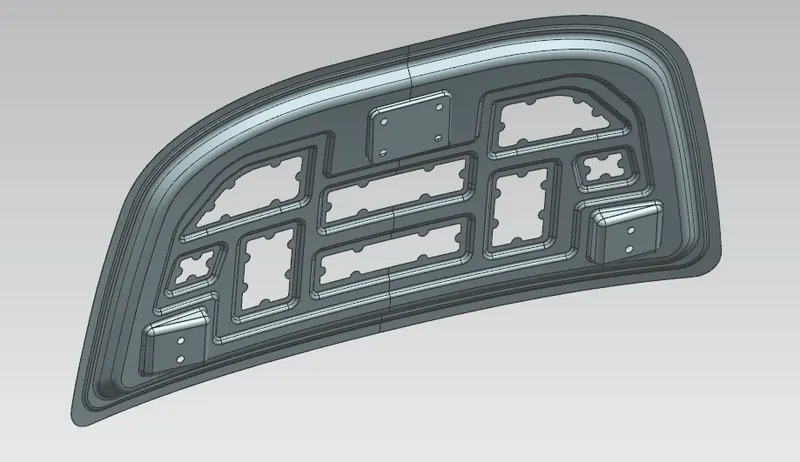
The inner panel provides strength and the outer panel acts as a metal cover. Inner panel also icludes the emboss to empower the hood, for the safety purpose of the pedastrains and the people inside
the car. the hinge is consisting of upper and lower brackets linkef by pivoted links. and both hinge brockets move partially while opening and closing.
Striker:
img): of hood striker
It bolts to the underside of the hood at the front. It engages the hood latch when closed.
Latch:
IMG): of latch in hood
It is placed in rest on the engine compartment for the opening and closing hood or bonnet.
IMG): of latch in hood
HINGES:
The hinge has two hinge parts that are connected with each other in an articulated manner and are movable relative to each other between a normal position and a protective position. The hinge parts are fixed in the normal position by a holding unit under impact with a holding force between the hinge parts.
Design parameters:
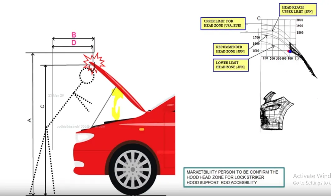
The head clearance zone is the clearance such that when the hood is in fully open condition it does not
hurt the head of the person that is standing next to the hood. This is controlled by the opening angle of
the hood. The angle of clearance varies from zone to zone and fron nation to nation.the manufacturing regions people with an average height of 5.5 ft and another region may have people with an average height of 6 ft. so person to person the height of clearance varies.
Gas stay:
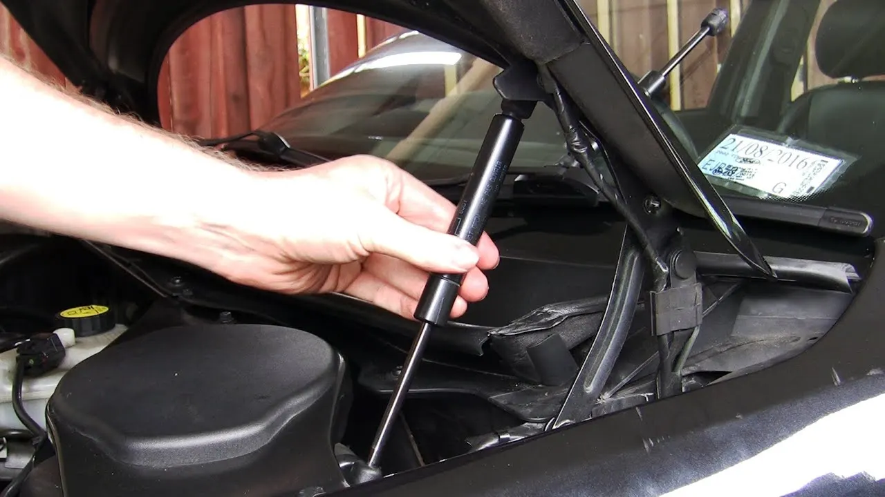
- these gas stays are used for the smooth opening of hood from rest to motion.
- The gas stay will assist in opening and holding the hood in position.
- gas stay uses an actuator to open and close the hood.
Supprot rods:(strut rods)
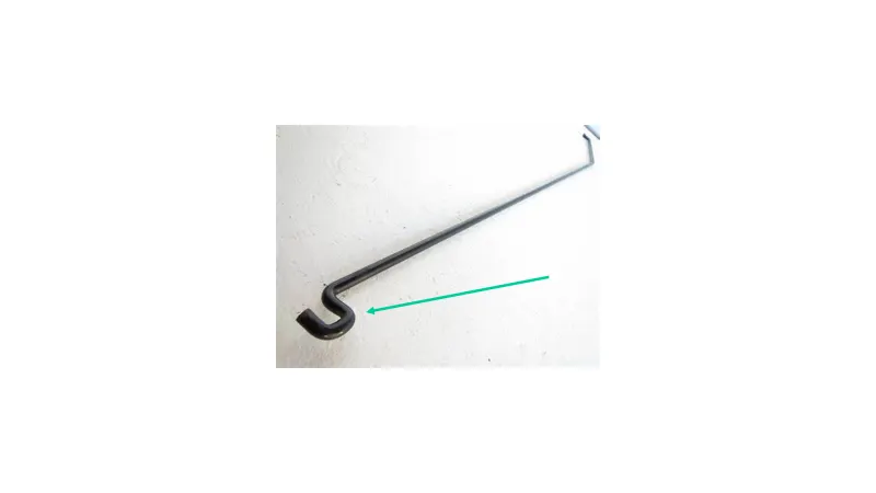
-
The design of the support rod is not linear but it should have some bends to increase the rigidity and strength of the rod. the support rod should be mounted such that it does not collide with other parts, also the support rod should be mounted on the opposite side of the battery to avoid interference with each other.
- these strut rode are used for supporting the hood in open position.
- in the rest position it is places inside the engine compartment. it is slightly bended to improve the strength.
pedastrains Safety parameters :
img); euro ncap system
Pedestrian safety is one of the important criteria which must be taken into consideration
during designing a hood. Based on the wrap-around distance and pedestrian head impact
zone, the hood is designed so that during a collision impact on the person must be reduced.
img): frontal crash
Wrap around distance is measured from the ground to the pedastrain head impact zone over outer surface
of the hood body and wrap around distance measured longitudinally of vehcle grounded.
the injusry caused by the fronal crash depend on shape of vehicle,speed and movement of car going
relative to the pedastrain waliking front of it. wrap distance plays important role in safety measurement
of a pedastrain.
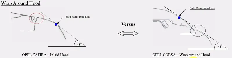
- Inlaid Hood The line which is drawn 45 deg. from the ground to the Side Reference of the car and which is a meeting point on the fender is called Inlaid Hood.
- Wrap Around Hood: The line which is drawn 45 deg. from the ground to the front surface of the Hood and which is the meeting point on the outer panel is called Inlaid Hood.
- Depending on the Inlaid Hood & Wrap Around Hood, we can design a hood for head impact in the fig shown position of the head impactor.
Approaching to cad:
master section given by the aesthetic developer :
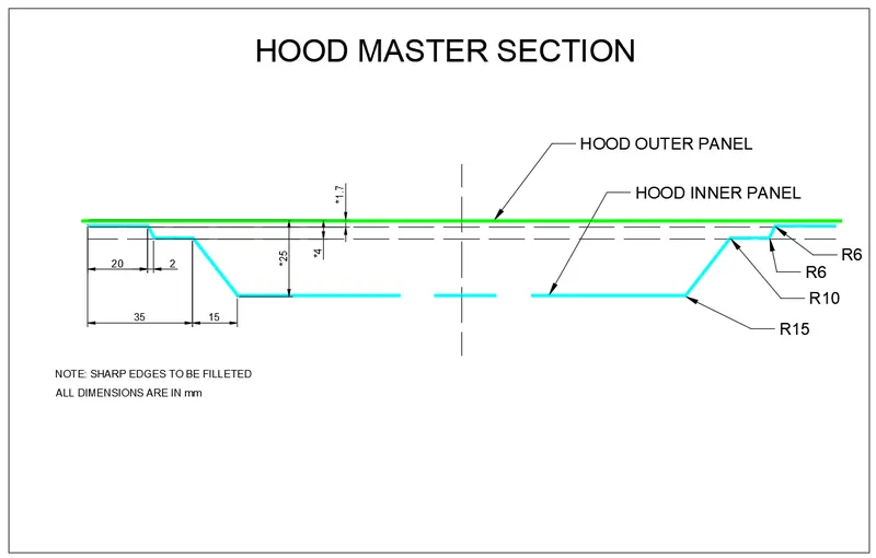
In the master section we have information to create the outer panel, inner panel, flanges we can create by offsetting the outer panel to given value. also emboss are placed to improve the strength of the hood assembly.
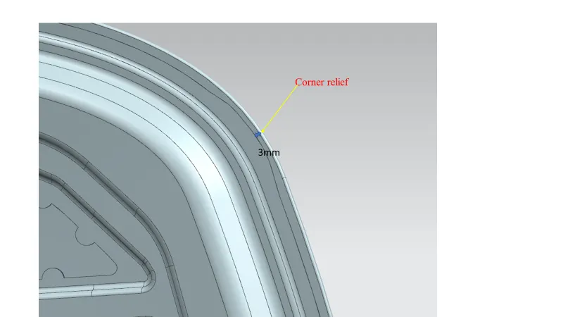
the inner panel is offsetted to 25mm allover at the downward direction.and all sharp edges should be filleted as there would not be any sharp corners. corner relief should be applied.
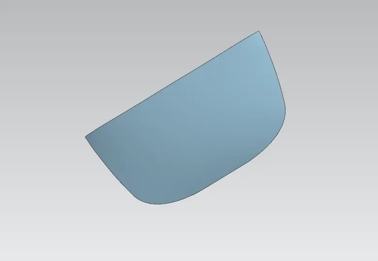
Outer panel:
Inner panel:
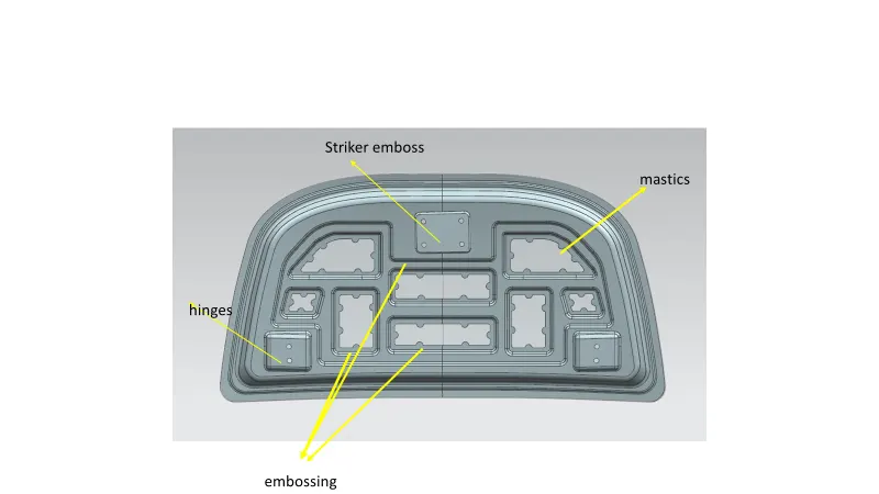
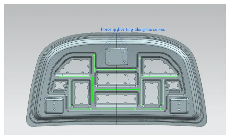
- emboss creation will reduce the vibartions happen inside the car.
- when the car hits obstacle the force reduce throught the curve shown above.
- This force can be reduced with embosses design, By giving some inclination angle to the embosses flanges.
- the force acting normal to the Hood can be diverted outwards of the hood.
Emboss required defination:
Emboss is created such that when force induced in middle of the hood which directly transmitted to the hinge point to provide better safety. If this type of emboss not provided the force transmission towards the centre of hood or vehicle which causes serious damage,
Mastics Data:
Mastic data should be provided in between hood upper panel and inner panel to achieve better NVH Range, to avoid the spot weld, to maintain the upper hood surface regularity.
Generally mastic diameter should be about 80mm which called strengthen diameter of the mastic rubber.
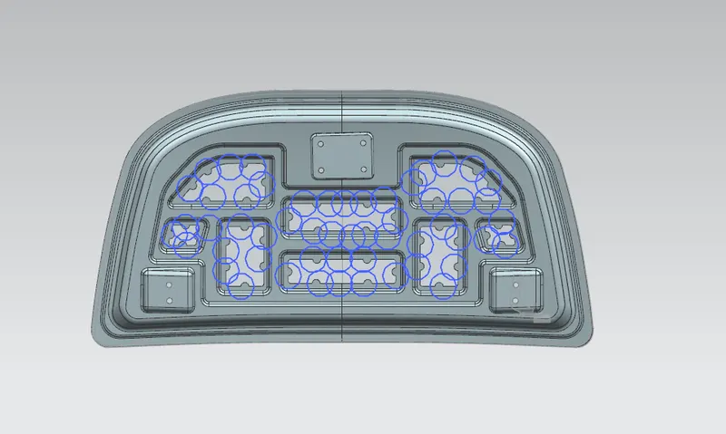
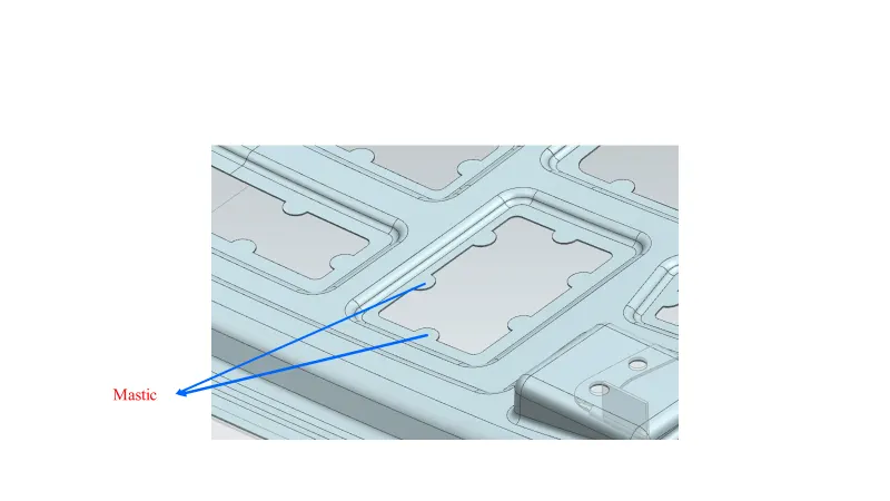
- Mastic is an adhesive that, along with thin-set mortar, is used to stick a sheet metal.
- While mastic does have strong points, such as great adhesive properties and adaptability to many substrates.
- high performance in wet areas is not one of its high points.
creation of striker emboss:
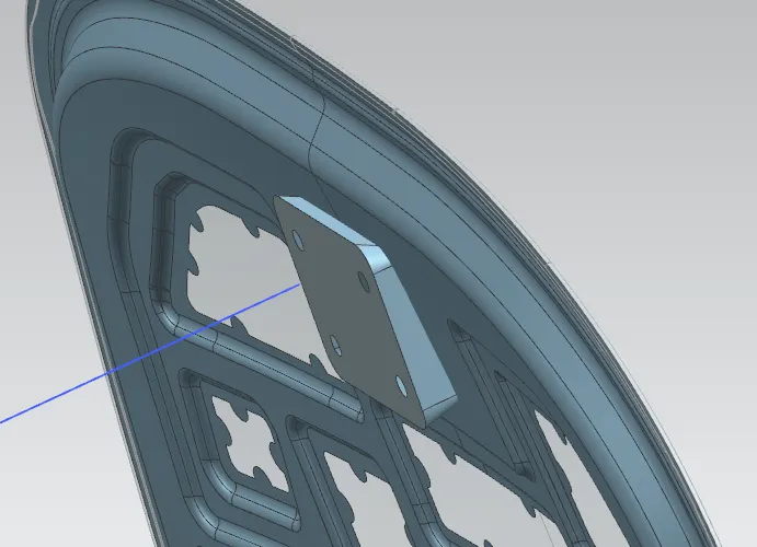
- to create striker we will use wave geometry linker to extraxt the upper face of the emboss
- then we will use the law extension command, after that we will sew the emboss and inner panel as well
- we will use trim and extend to get the final trimmed body.
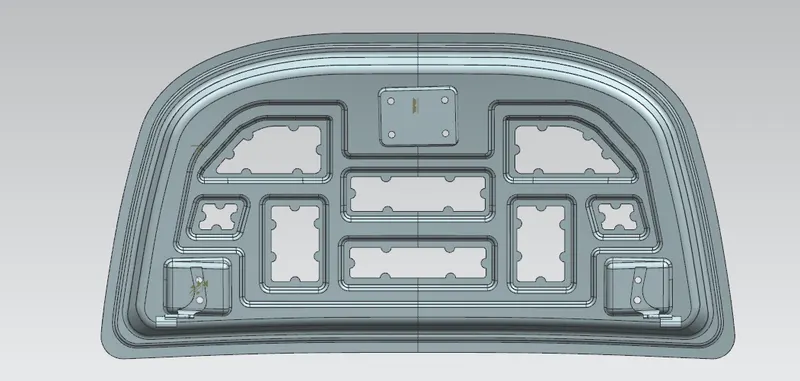
Hinges :
assembling the striker:
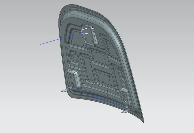
- the striker is assembled by making trajectory from the mid point of the inner pannel.
- the midpoint is created by using parellel line between the hinges placed on the emboss.
- by using assembly constrains we can able to place the striker above the emboss.
The commands which are used in the hinges are fix, parallel, alling and touch in striker the aling & touch is used for assembling.
Data to be used:
Hood Thickness Information
- Outer Panel Thickness = 0.75mm
- Inner Panel Thickness = 0.75mm
- Reinforcement Thickness = 1.5mm
Manufacturing process:
HEMMING OPERATION:
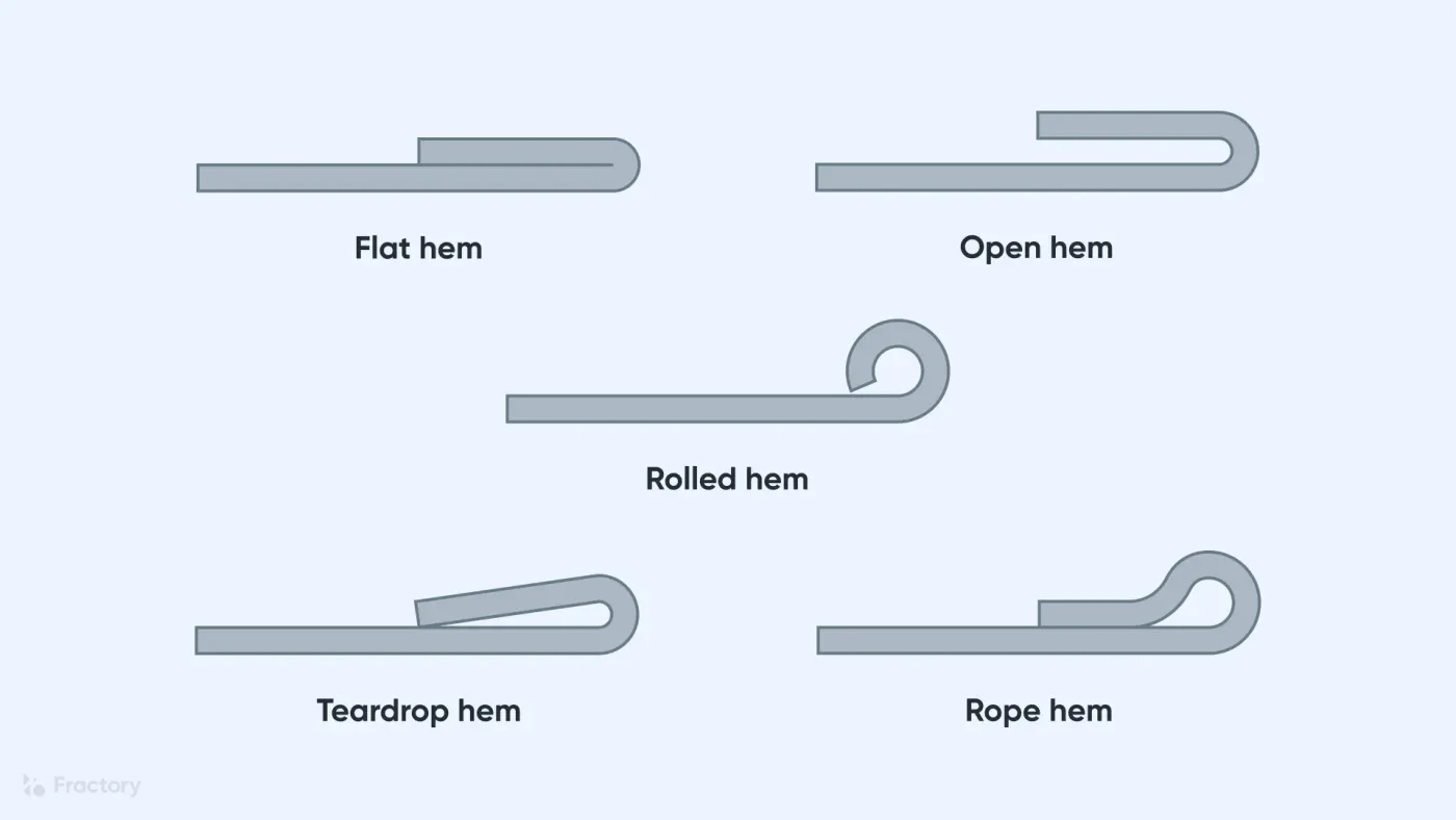
Hemming is a common metalworking process mainly carried out to reinforce an edge, hide burrs or just improve the overall appearance of sheet metal parts. When hemming is carried out in a way that a joint between two sheet metal parts is created.
Defination of hemming:
Hemming in sheet metal operations refers to the bending of a sheet metal edge onto itself.
It is very similar to edge stitching in clothes. Similar to how an edge stitch strengthens the edge and makes it more durable,
a hem imparts strength to the metal edge and improves its appearance. The edge of one part may also be folded onto another part to create a joint.
Hemming is usually done in two stages. The first stage creates an acute bend using acute tooling (V die) followed by a flattening of the return flange using a flattening die.
A complete list of hemming benefits on a sheet metal product is as follows:
-
Hems strengthen the sheet metal edge
-
They improve the surface appearance and surface quality
-
They hide defects such as rough edges and burrs
-
They can connect parts
-
They make the edges safer to handle
Open hem
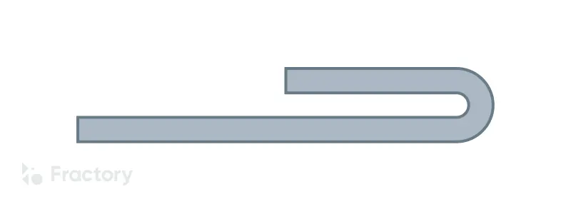
In an open hem, the returning flange is folded over the sheet metal but there remains an air pocket between the two. The bend angle in this hem type is also 180 degrees.
Img): point view of the hemming on the given hood outer panel
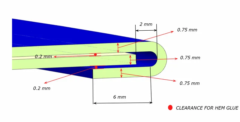
The hemming is to be done by having above master section reference.
Giving relieves to the corners:
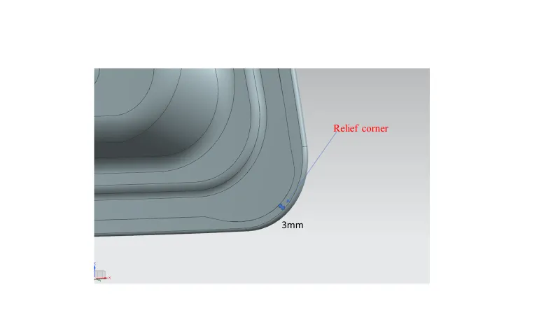
Deep drawing oeprtion used to create the emboss:
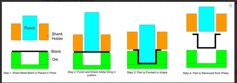
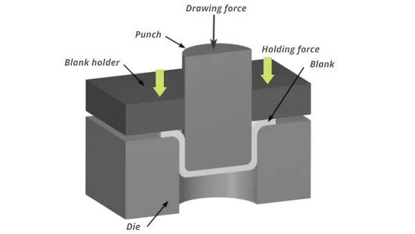
Deep drawing is a metal forming operation in which the sheet metal is stretched into a desired shape by the mechanical action of a punch.
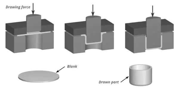
The punch pushes the sheet metal blank downward and forces it into a die cavity which ultimately forms a shape of the desired part.
During the deep drawing operation, the tensile forces cause the sheet metal blank to plastically deform into a cup shaped part.
Generally the term deep drawing is referred to a drawn part which has depth more than its diameter.
The parts drawn by using a deep drawing process can have different cross sections like straight cross section, tapered cross section as well as cylindrical and rectangular parts can be drawn.
For deep drawing operation, the ductile metals like brass, copper, aluminum and mild steel show good drawability even at room temperature.
Deep drawing process in sheet metal:
Deep drawing process requires 4 main components.
- Blank
- Blank holder
- Punch
- Dies
A blank is a sheet metal piece which can be in the form of disc or rectangle shape. This blank is cut from a sheet metal which is then kept over the die for its further deep drawing operation.
This sheet metal blank is clamped down over a die with the help of a blank holder.
The punch is then moved down which draws the sheet metal into a shape of a die.
Generally, the power applied to the sheet metal can be produced by using a hydraulic punch.
The die and the punch material should be strong which can resist the pressure formed during the drawing operation.
Hence, the dies and punch are made up of tool steel or carbon steel.
For some deep drawing operations, the complete metal drawing may takes few sequences of steps. This series of steps are called draw reductions.
In each series, the punch gradually stretches the metal deeper than the previous one.
When the desired shape is achieved in the final step, the drawn part is removed from the die.
The extra metal remains as a flange around the drawn metal part (under the blank holder). This can be trimmed off easily.
CONCLUSION: