Hood design
Objective:
To design a hood outer panel, inner panel and assemble the reinforcements in Semens NX.
Introduction:
A hood is also known as ‘bonnet’, it is a metal cover to protect the engine and it’s components from top. It is hinged at the ends, so that it provides access to repair and maintain the engine.
Parts under hood:
- Engines
- Spark plugs
- Coolants
- Batteries
- Radiator and etc.
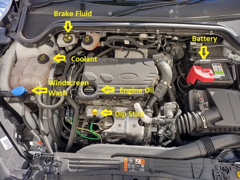
All the above components are protected by the hood from high, low temperatures, from rain, dirt and stones. A hood is engineered to reduce the collision impact on the engine and the driver by distributing the collision force to the either side of the hood. Pedestrian safety is also considered in the hood design.
Hood outer panel is provided along with hinge assembly and striker. Master section is keenly studied to proceed further with the design.
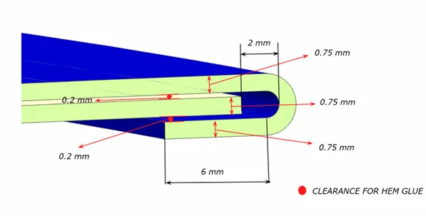
Hood Thickness Information
Outer Panel Thickness = 0.75mm
Inner Panel Thickness = 0.75mm
Data from the Master section:
 |
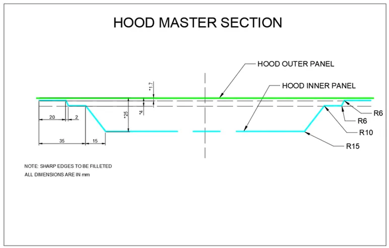 |
There is a hood outer panel as the Class A surface. Hood inner panel has three flanges at various depths. Hood outer panel has a hemming flange to connect both the outer and inner panel.
Components:
Hood outer panel:
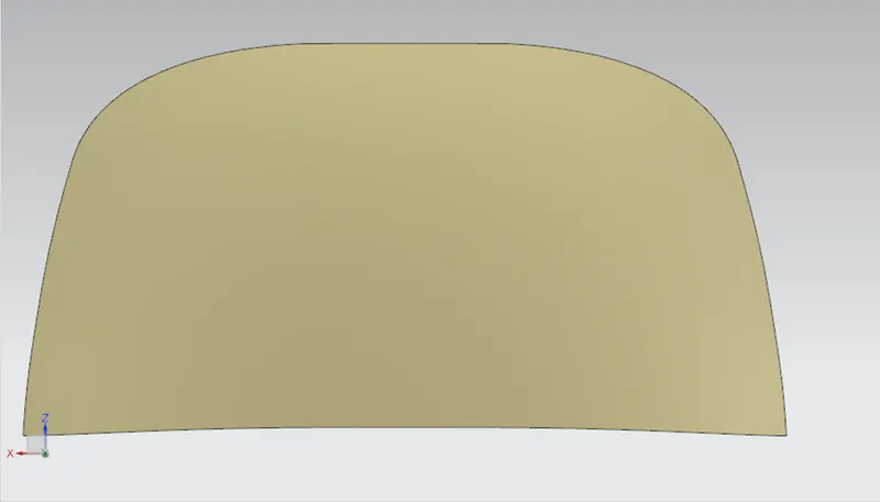
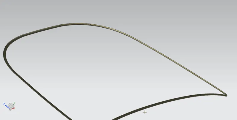
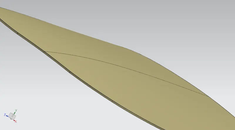
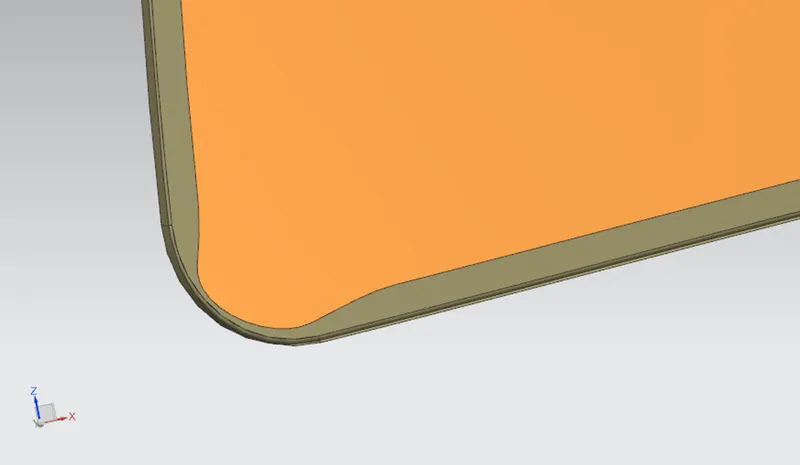
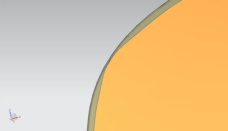
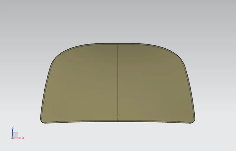
A hood outer panel is provided as shown in the figure. The outer panel is extracted from the given original face. Hood outer panel has a hemming flange. To create hemming flange, the outer panel is offset to 2.65mm in downward direction. Using offset curve in face command a boundary is created with 6mm offset on the face. Hemming flange is created by trimming the face using the boundary created on the face of the offset surface. Using law extension command a 90degree projection is created with 4mm length. All the flanges are joined using 3 face blend. Reliefs are also provided on the hemming flange at the corners. The sheet is provided thickness of 0.75mm thickness with thicken command.
 |
 |
 |
 |
 |
 |
Inner panel:
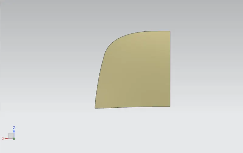
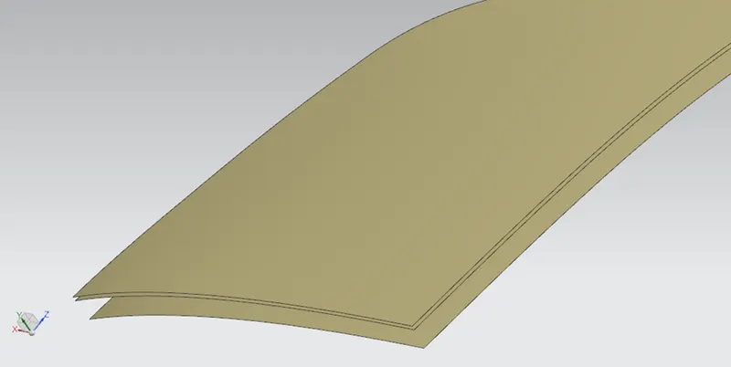
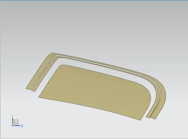
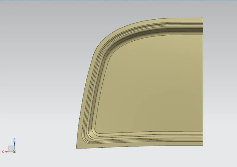
Inner panel is extracted from the outer panel as dissociate surface. There are three flanges in the inner hood panel. To create flanges in the inner panel, the inner panel is offset 3 times at three different lengths. First flange is created by offsetting 1.7mm, second by 4mm and third flange is created by offsetting by 25mm. Using trim sheet command the flanges are trimmed as per the master section. Using through curves the open spaces are joined. All the surfaces are joined together using sew command. Using edge blend fillet radius is provided to the surface.
 |
 |
 |
 |
 |
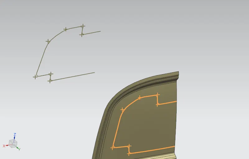 |
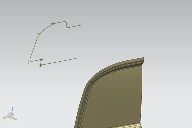
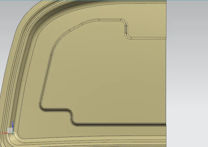
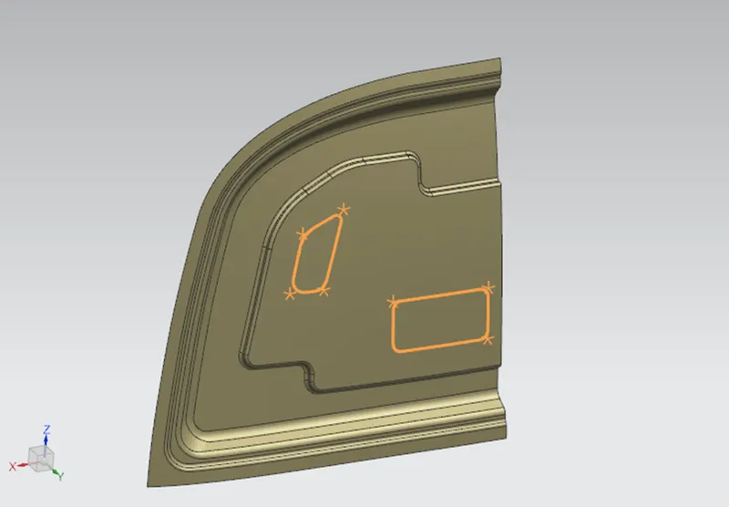
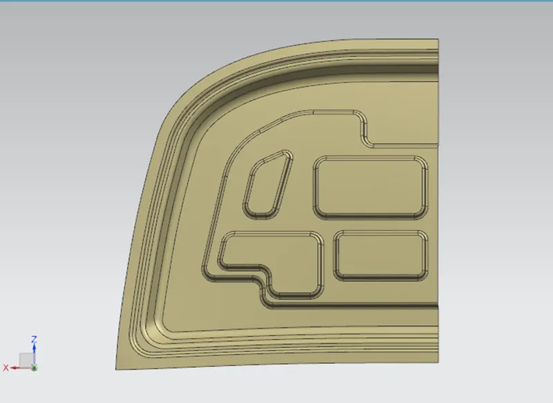
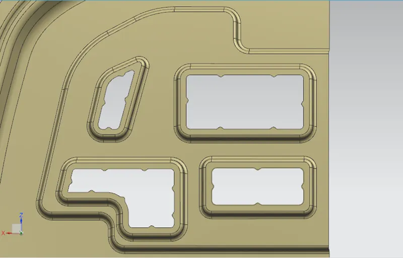
Embosses are created on the inner panel to create mastic points and to distribute the collision forces. To create embosses a sketch is drawn at on a plane and the sketch is projected on the surface. Using emboss command first emboss is created on the inner panel with 10mm length and 7degree draft angle. To create another emboss another sketch is drawn on a plane and projected on the surface as shown in the figure. Again using emboss command the remaining embosses are created at 8.5mm length with 10 degree draft angle. All the embosses are filleted by edge blend command. Mastic points are created on the embosses as shown in the figure.
 |
 |
 |
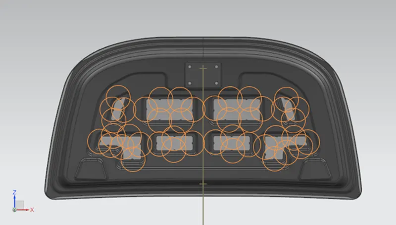
To create mastic points the outer edge of the embosses are projected and offset inside. Circle are created on the curve with minimum 8mm distance between two. Using bridge curve tool the curves are created as shown in the figure. Composite curve command is used to extract the required shape of the curve. Then the curve is projected on the surface, using trim command the sheet is cut into desired shape.
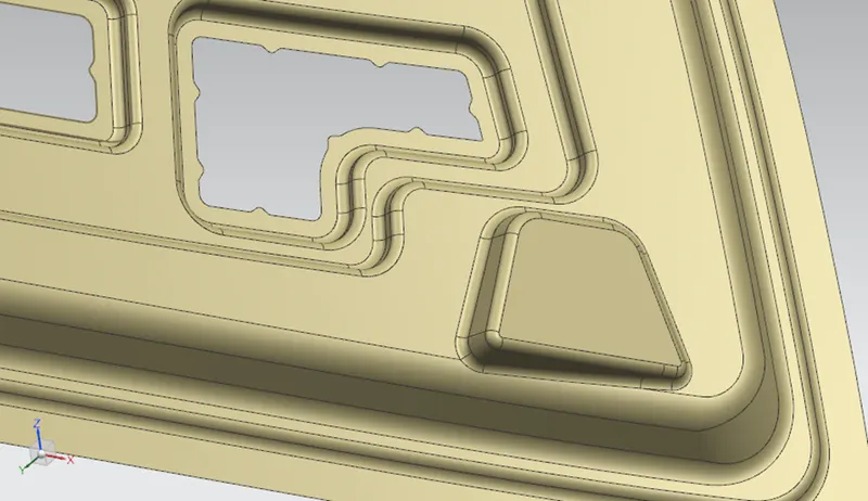
Embosses are also created for hinge assembly and striker. To create emboss for hinge assembly, unlike other embosses the hinge assembly emboss should not have any angle with respect to surface. It should have zero inclination. A datum plane is created parallel to the surface. A sketch is drawn, projected on the inner panel. Using emboss command emboss is created for hinge assembly parallel to datum plane. Before mirroring the surface along XY axis. The surface is extended and trimmed with the reference of XY plane. This is done to remove irregularities on the surface before mirroring. After creating the mirrored geometry both the surfaces are joined together using sew command. The sheet is thickened to 0.75mm using thicken command.
Reinforcements:
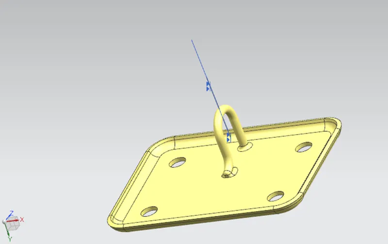
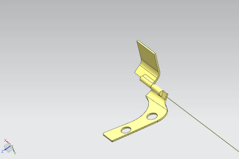
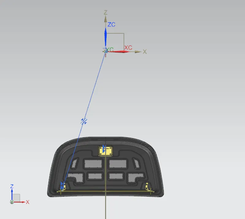
Two parts are considered as reinforcements in this project, hinge assembly and striker. Hinge embosses are created on the inner panel. Hinge assembly is fixed onto inner panel using constraints in assembly workbench as shown in figure. The hinge assembly is mirrored onto the other emboss using mirrored geometry tool.
 |
 |
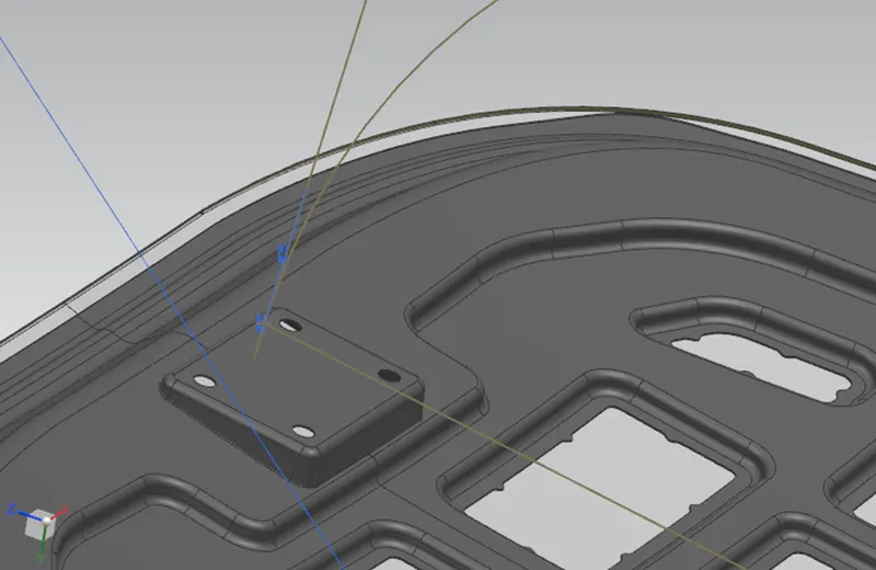 |
An emboss is created for the striker on the inner panel as shown here. The striker is aligned using assembly workbench.
Latch trajectory:
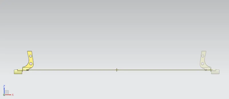
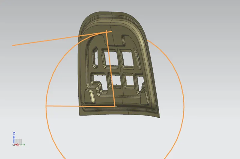
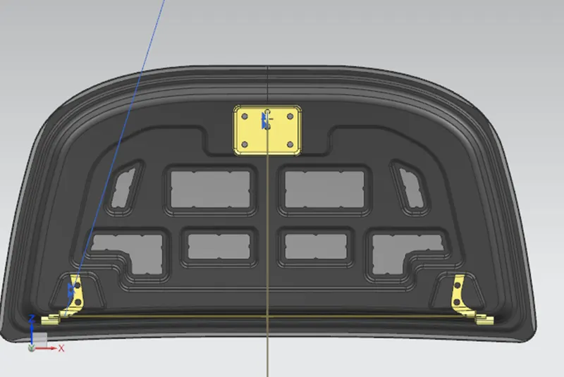
A line is created joining both the hinge assemblies. A point is created on the line at the centre of the two hinge assemblies. A circle is drawn with 685mm radius. A line is drawn perpendicular to the plane and another line is drawn with certain angle. An intersection point is created on the circle with respect to line drawn with an angle. The circle passing through striker is the latch trajectory.
 |
 |
Mastic points:
Mastic sealants are gum type of sealants which joins outer and inner panel together. Riveting and welding is avoided so that the aesthetics of the outer panel remains the same. Mastic points are created so that mastic sealants are placed at that points. Each point cover 80mm in diameter. Hemming is given only at the edges of the panels. Mastic sealants can reach where hemming cannot cover.
Hemming:
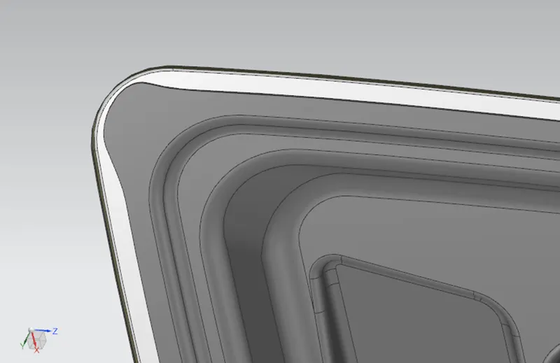
This process is also used to join outer and inner panel. The joining is done by creating an extra surface of the outer panel and folding the edge of the outer panel over other parts. This cannot be done in a single step. Incremental steps are taken by the roll hemming to fold the sheet. Reliefs are provided at the round corners to avoid folds and wrinkles on the sheet.
Deep drawing:
A sheet metal blank is radially carried into a forming die during the deep drawing process by the mechanical action of a punch. Thus, it is a shape change process that keeps the material. When the drawn part's depth is more than its diameter, the procedure is referred to as "deep" drawing. This is accomplished by redrawing the component using a number of dies.
Final assembly:
 |
 |