Gate Valve Parametric Study
AIM: parametric study of gate valve in fluent
Methodology
- gate valve use
- fluent setup
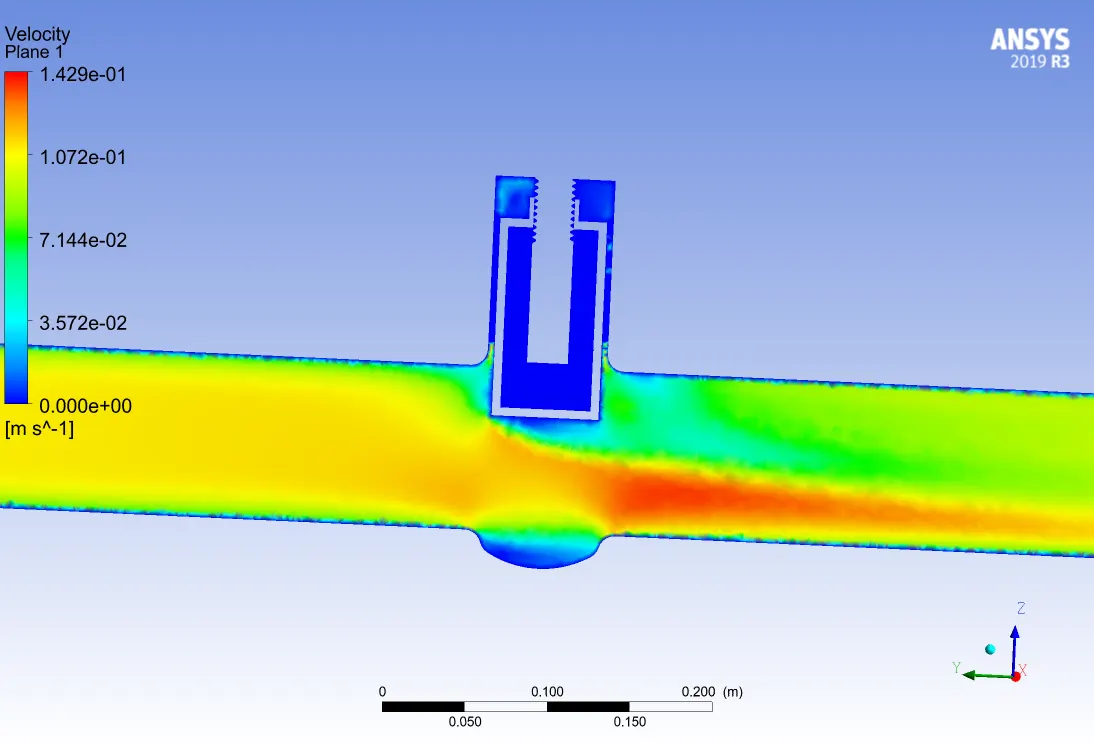
- Velocity profile
- Flow coefficient and flow factor calculation
- Summary and graph of coefficients
- learning outcome
Gate valve:
gate valve, also known as a sluice valve, is a valve that opens by lifting a barrier (gate) out of the path of the fluid
Gate valves are often used when minimum pressure loss and a free bore is needed. When fully open, a typical gate valve has no obstruction in the flow path resulting in a very low-pressure loss, and this design makes it possible to use a pipe-cleaning pig. A gate valve is a multiturn valve meaning that the operation of the valve is done by means of a threaded stem. As the valve has to turn multiple times to go from open to the closed position, the slow operation also prevents water hammer effects.
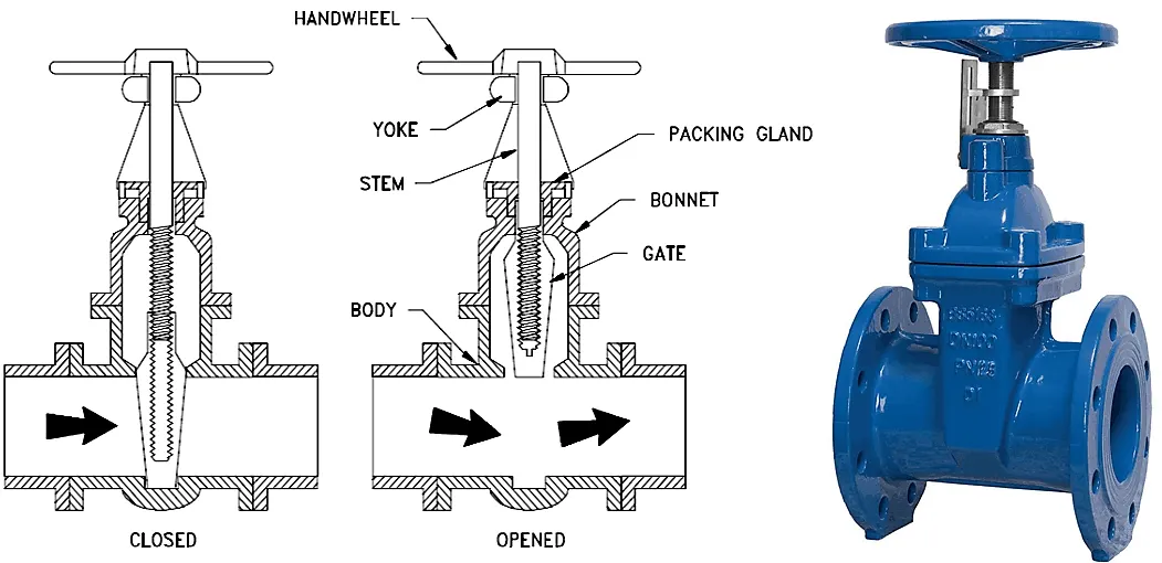
Parallel gate valves:
The parallel gate valves use a flat gate between two parallel seats, and a popular type is the knife gate valve designed with a sharp edge on the bottom of the gate.
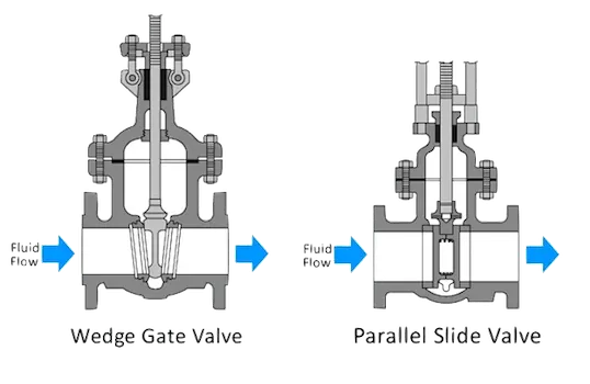
wedge type gate valves:
it has a disc that is in the shape of a wedge that seats against two inclined seats. Solid wedges are used in high flow or turbulent applications such as steam service. The solid design also minimized the vibration and chatter
- FLUENT SETUP
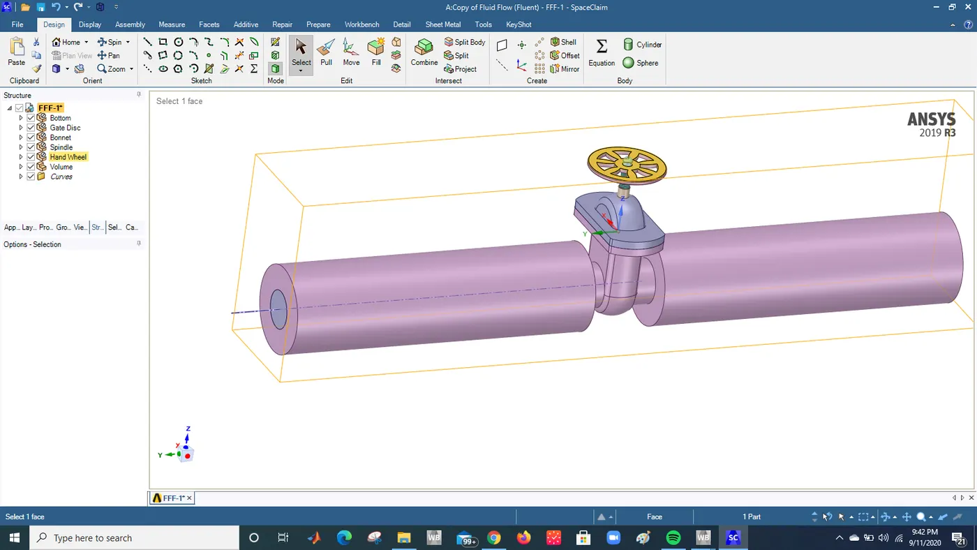
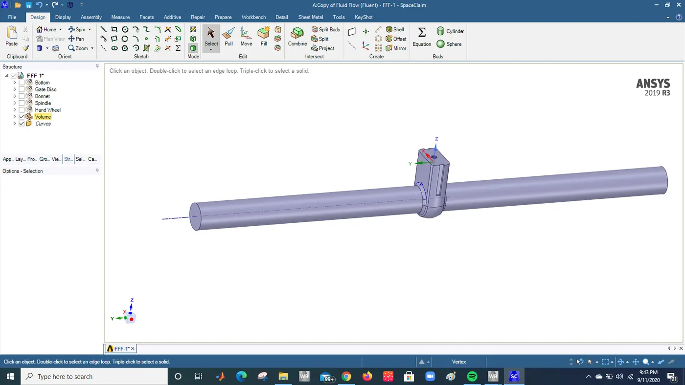
Upload a geometry of gate valve and extract the necessary volume for fluent
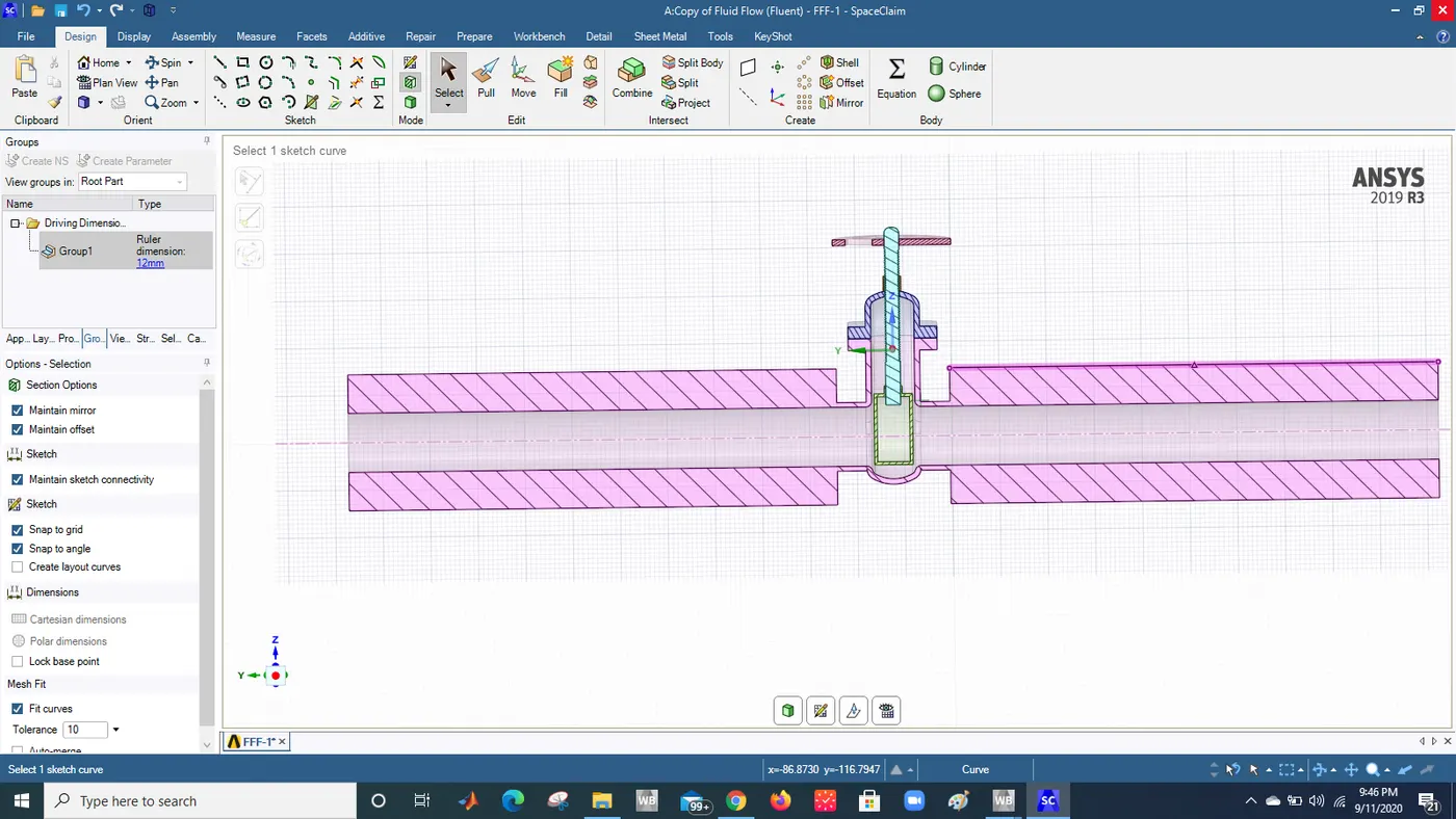
Make the gate valve dimension as a parametric dimension and make a group of it. For the first case it will be 10 mm as we are going to open 10 percentage
Extracted volume
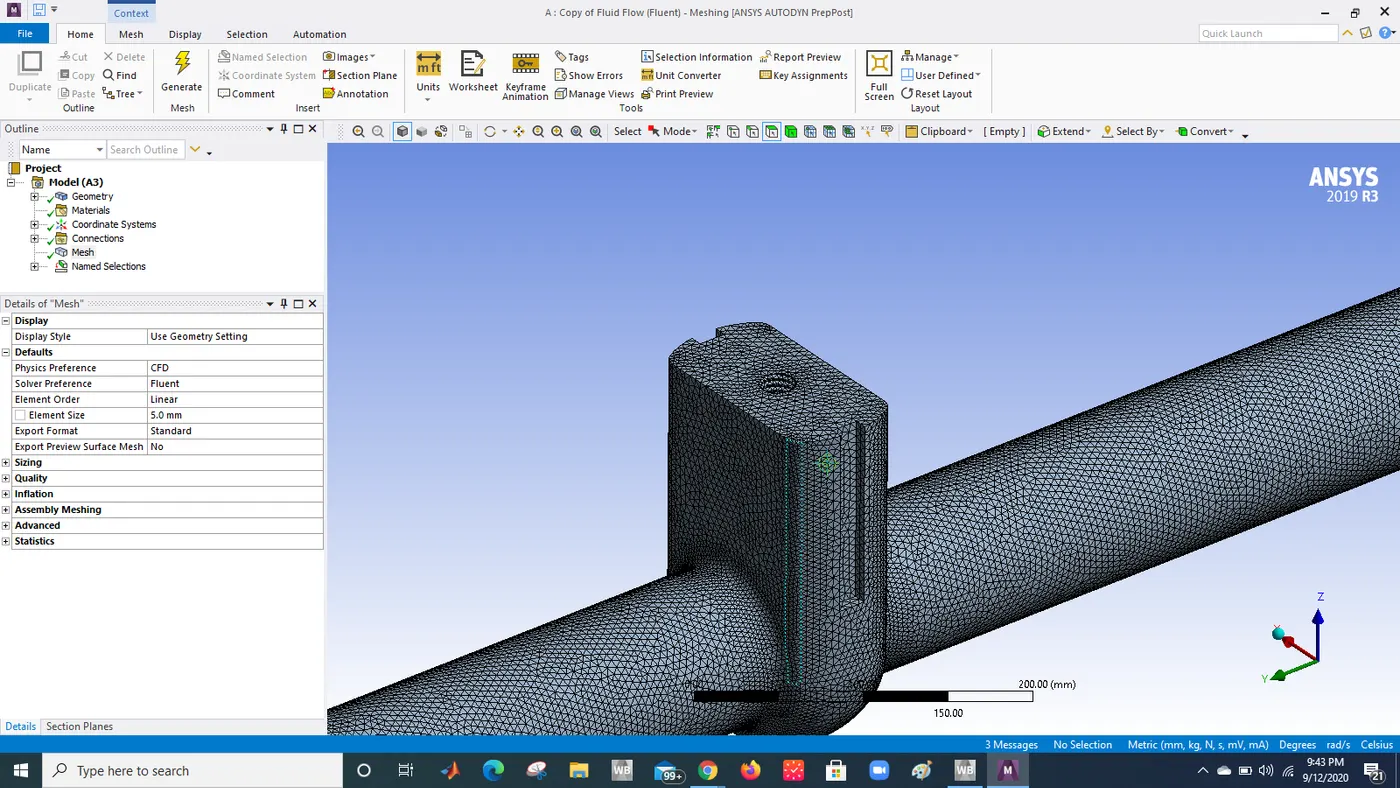
Meshing
Type: Tria
Mesh element: 5 mm
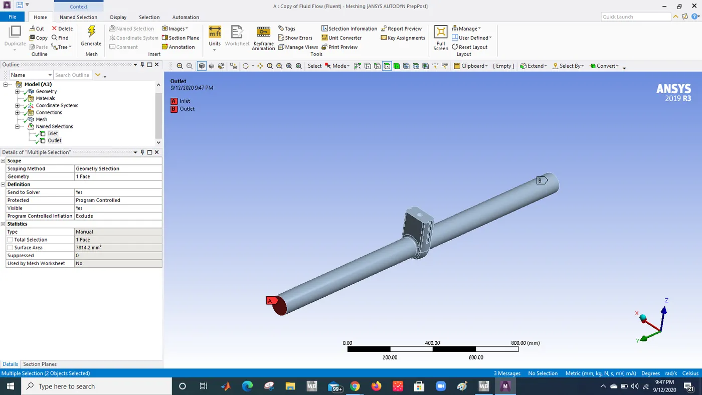
Boundary conditions inlet and outlet
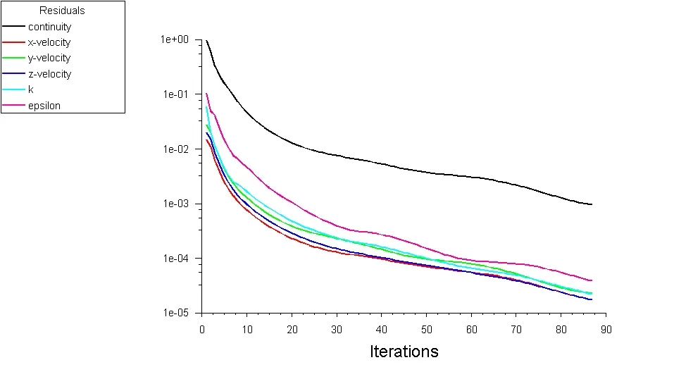
Fluent setup for all cases(10 percentage)
- Type: pressure solver
- Time: steady
- gravity -z
- Model: k epsilon, realizable and scalable equation
- Boundary conditions:
- Inelt conditions: 10 gauge
- oUtlet conditions: 0 guage
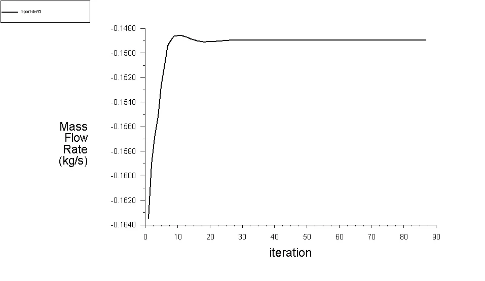

For all the other cases doing a parametric study for the study of mass flow rate.
Mass flow rate data are given below for 10 to 80 percent opening.
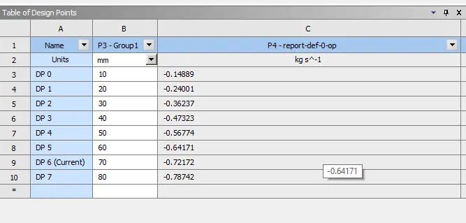
From the flow rate we can see that its obvious thing is that once you open the valve slowly the flow rate will increase as the flow area will increase gradually.
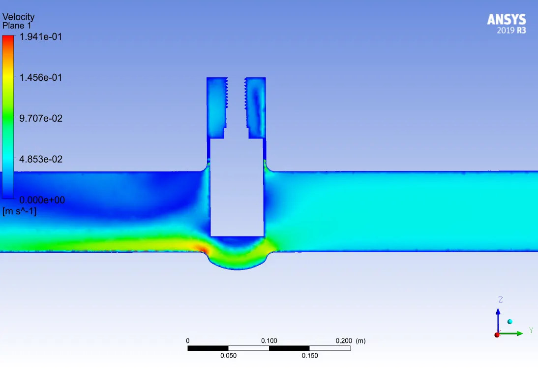
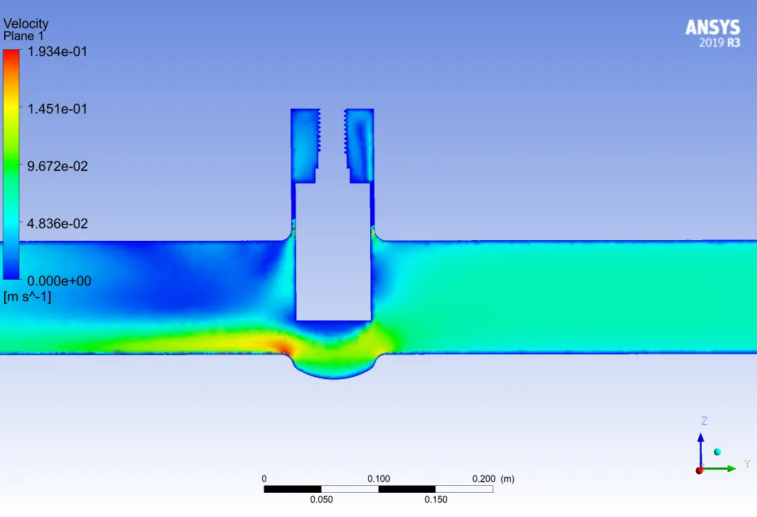
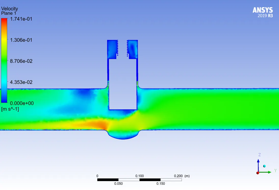
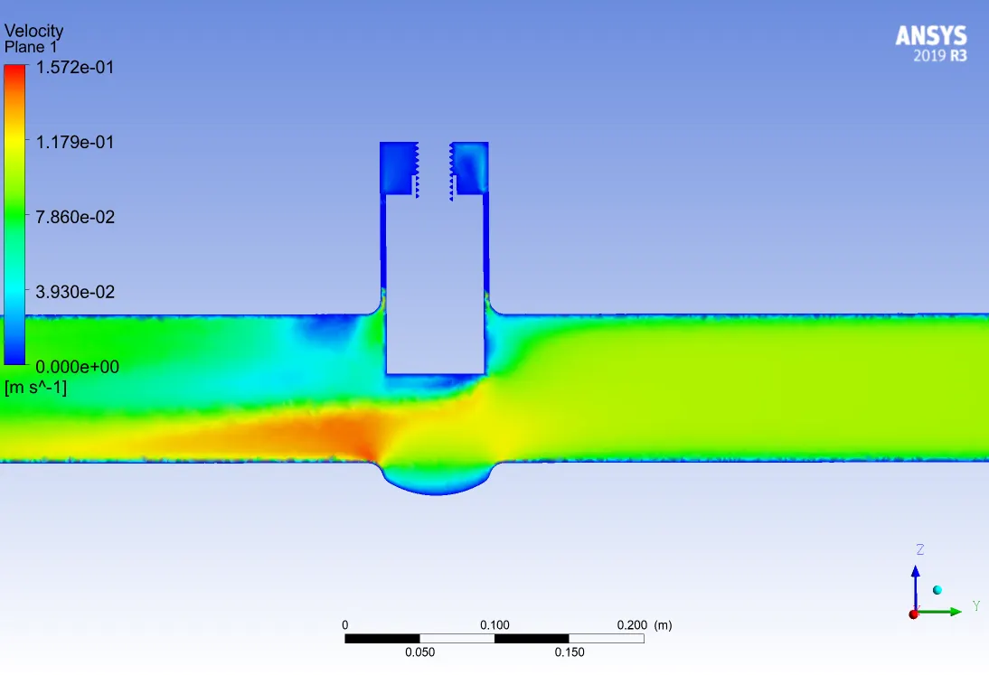
Velocity contours for all cases when gradually opens the valve.
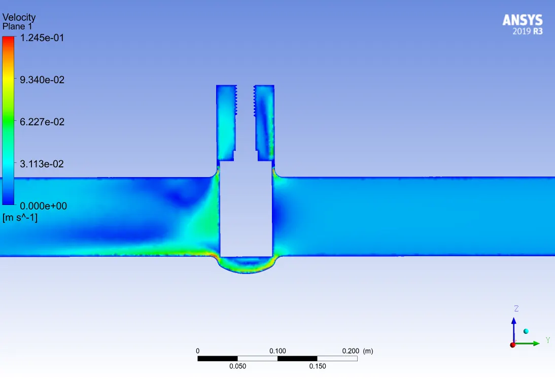
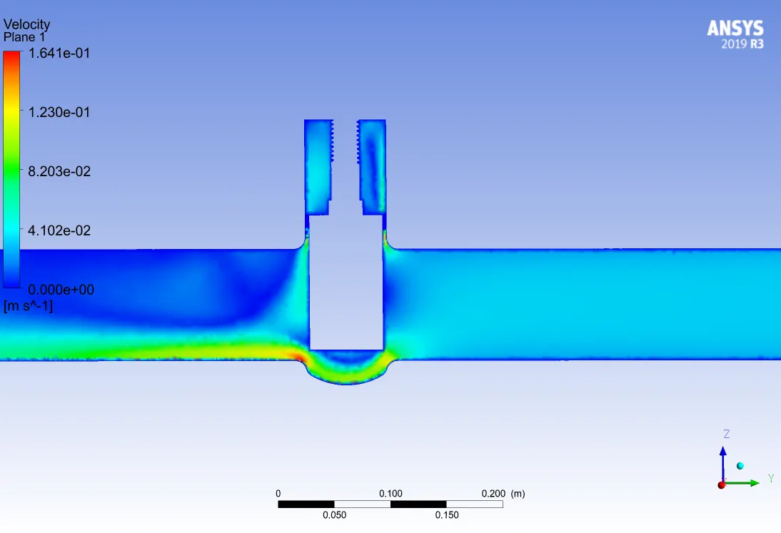
Flow coefficient(Cv) and flow factor(Kv)
- Each valve has its own coefficient. This depends on how the valve has been designed to let the flow going through the valve. If the valve is going to open through the time, then the coefficient should be selected in such a way that, It should obtain a lower pressure drop. At the same flow rate, a higher flow coefficient means lower drop pressure across the valve.
- The flow coefficient of a device is a relative measure of its efficiency at allowing fluid flow. The valve coefficient is the valve's capacity for a liquid or gas to flow through it. It is technically defined as “the volume of water at 60°F (in US gallons) that will flow through a valve per minute with a pressure drop of 1 psi across the valve.
Flow coefficient (Cv)=`Q sqrt((SG)/( PRESSURE DROP))`
Where Q is flow rate (US gallons per minute)
SG =specific gravity
Pressure drop in psi.
- Kv is the flow coefficient in metric units. It is defined as the flow rate in cubic meters per hour [m3/h] of water at a temperature of 16º celsius with a pressure drop across the valve of 1 bar.
Cv is the flow coefficient in imperial units. It is defined as the flow rate in US Gallons per minute [gpm] of water at a temperature of 60º Fahrenheit with a pressure drop across the valve of 1 psi. - For our case pressure drop will be the same for each and every opening scenario. which is 10 pa.
- the specific gravity of water= 1
- Online calculator link : https://www.engineeringtoolbox.com/flow-coefficients-d_277.html

- Here negative flow rate is showing mass is going out from the system.
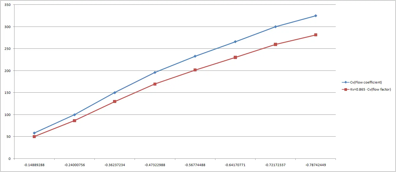
- on x axis Flow rate is shown and Flow factor graph point and flow coefficient graph points are shown on Y-axis.
- From the graph and all data conclusion Once you increase the flow rate the pressure drop will decrease and the flow coefficient will increase. Industry flow coefficient should be chosen in such a way that there will be minimum pressure loss. So that energy loss will be less.
- For lower the Flow rate the lower the backpressure, Lower backpressure is related to fluid viscosity, which means higher the pressure drop.As you increase the flow rate back pressure will increase and pressure drop will decrease, with increase of flow rate Cv and Kv will increase as well For increase the flow rate the velocity should be increased. Hence Kv and Cv should be chosen efficiently.
Learning outcome
- Parametric cases setup and its use
- Gate valve use and analysis
- Flow factor and flow coefficient study on valve
- Flowrate and pressure drop significance