Gate Valve Parametric Study
AIM: To perform a parametric study on the gate valve simulation by setting the opening from 10 % to 80% and to calculate the flow coefficient and flow factor for each opening and plot the graph.
Theoritical Backgound:
GATE VALVE
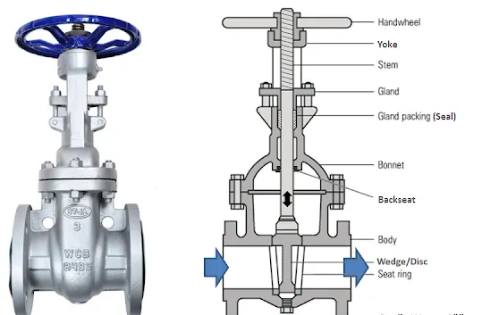
A gate valve, also known as a sluice valve. It is a valve that opens by lifting a barrier (gate) out of the path of the fluid. Gate valves require very little space along the pipe axis and hardly restrict the flow of fluid when the gate is fully opened. The gate faces can be parallel but are most commonly wedge-shaped (in order to be able to apply pressure on the sealing surface).
Gate valves are used to shut off the flow of liquids rather than for flow regulation. When fully open, the typical gate valve has no obstruction in the flow path, resulting in very low flow resistance. The size of the open flow path generally varies in a nonlinear manner as the gate is moved. This means that the flow rate does not change evenly with stem travel. Depending on the construction, a partially open gate can vibrate from the fluid flow.
Gate valves are designed for fully open or fully closed service. They are installed in pipelines as isolating valves, and should not be used as control or regulating valves. Operation of a gate valve is performed doing an either clockwise to close (CTC) or clockwise to open (CTO) rotating motion of the stem. When operating the valve stem, the gate moves up- or downwards on the threaded part of the stem.
Parametric Study
Parametric studies allow you to nominate parameters for evaluation, define the parameter range, specify the design constraints, and analyze the results of each parameter variation.
A parametric study requires the following:
- Design Objective is set to Parametric Dimensions
- Parameters nominated for use in the simulation
- Parameter ranges identified
- Design criteria specified
- Various configurations generated
Geometry:
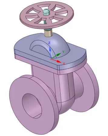
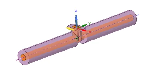
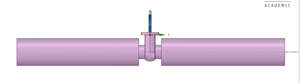
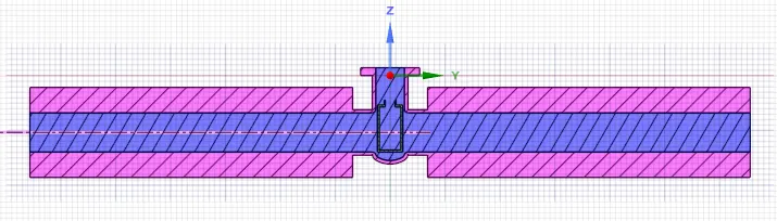
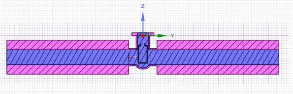
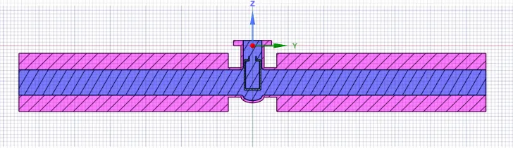
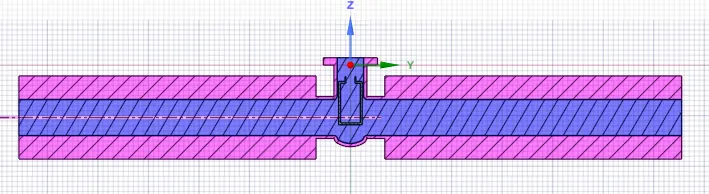
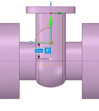
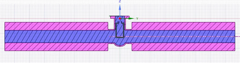
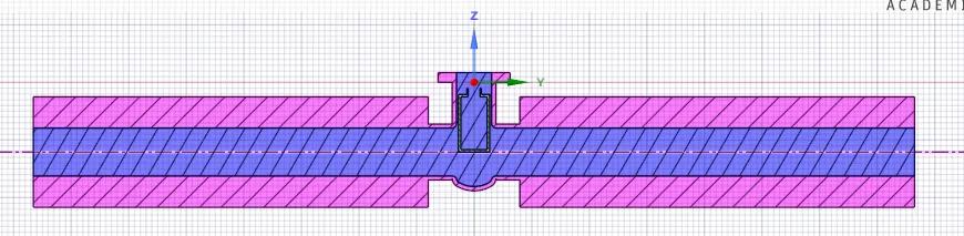
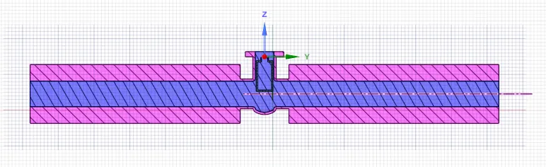
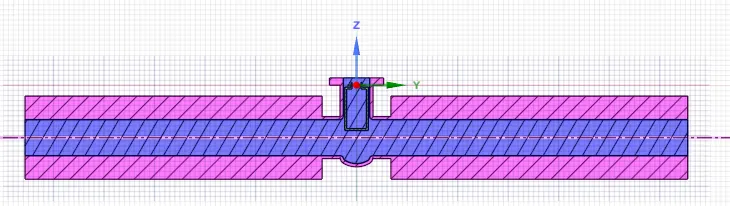
The geometry of the Gate Valve imported in to the Space claim is as shown below
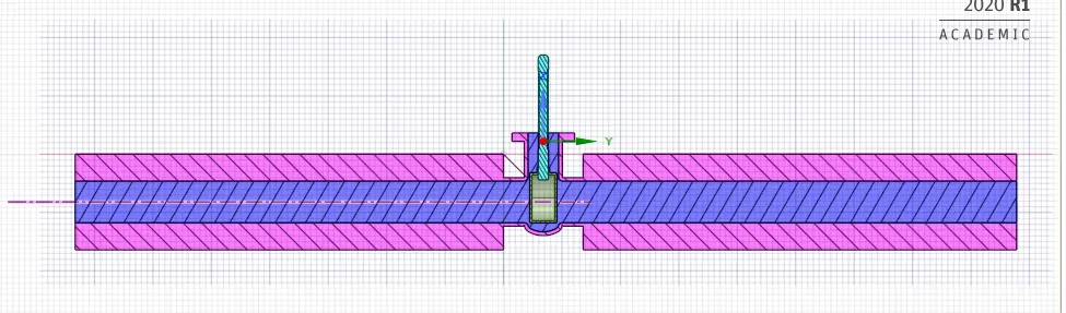
We have to extract the Fluid Volume by selecting the inlet and outlet edges to obtain the below Geometry
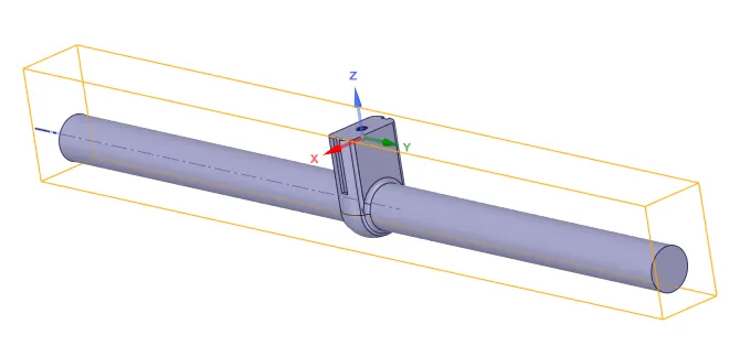
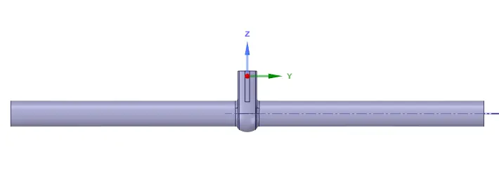
The extracted fluid volume is updated as per the context
Meshing:
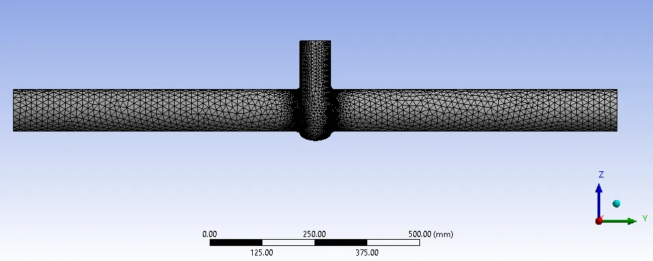
Default Element size - 50mm, Number of Nodes -29802, Number of Elements - 140283
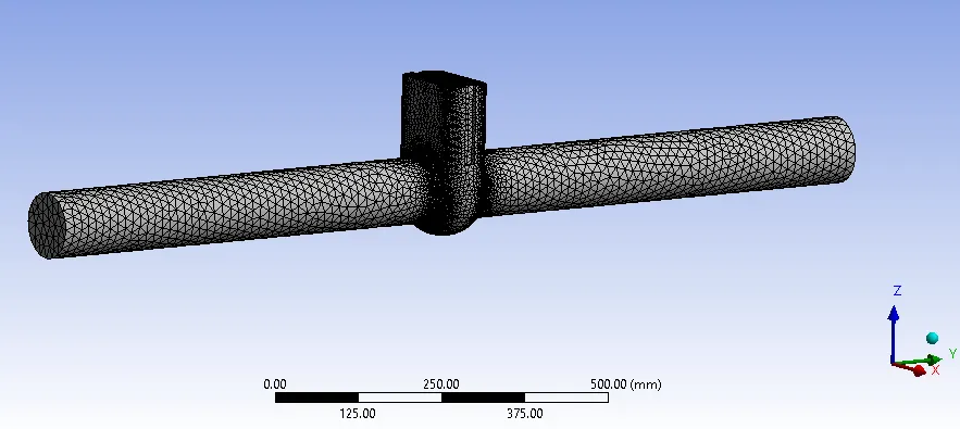
Creating the Named Selections
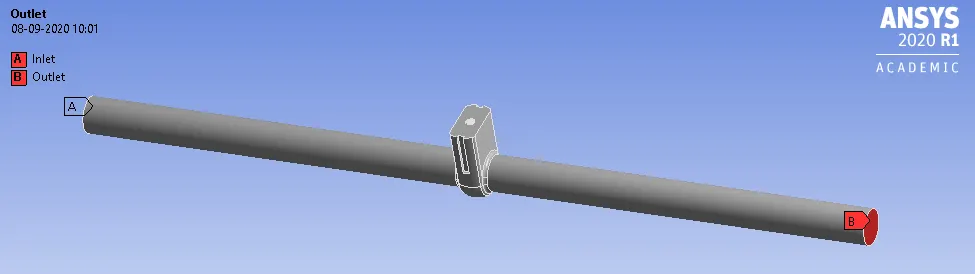
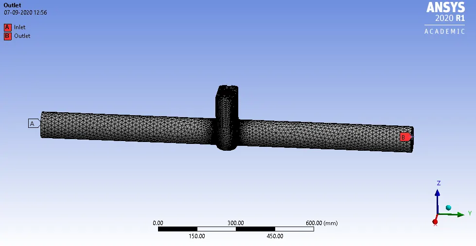
Fluent Setup:
Solver - Steady State solver
Type - Pressure based
Model - K-epsilon, Realizable, Scalable wall functions
Materials, - Fluid - Water, liquid
Boundary Conditions - Inlet - Pressure inlet with Gauge pressure = 10 Pa
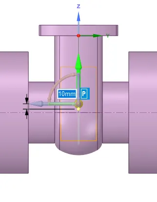
Case 1: Gate Disc lift = 10mm
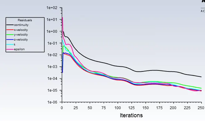
Residual Plots
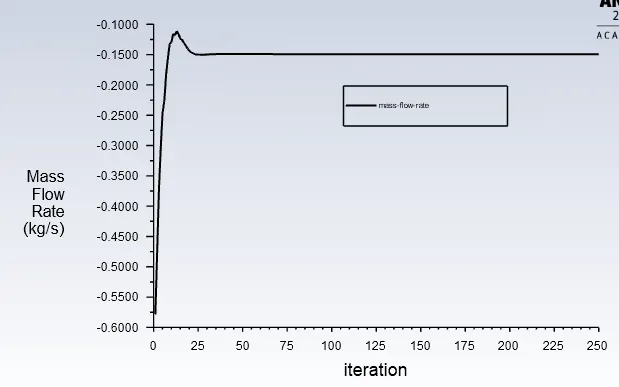
Mass Flow rate
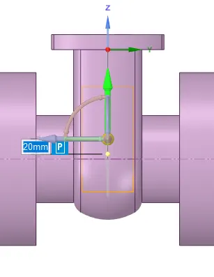
Case 2: Gate Disc lift = 20mm
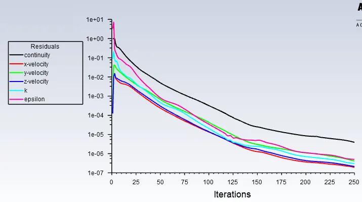
Residual Plots
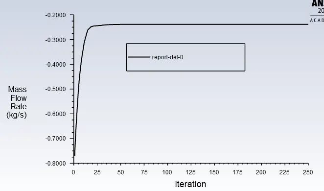
Mass Flow rate
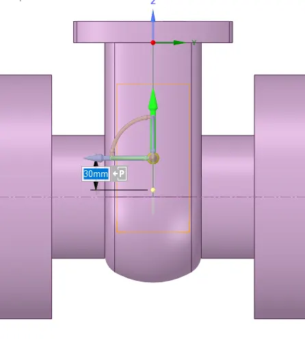
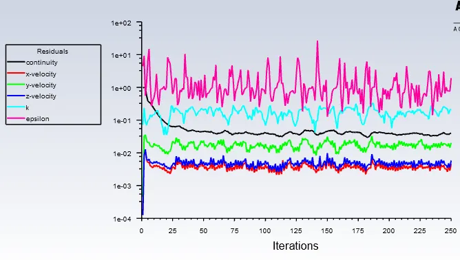
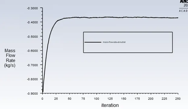
Case 3: Gate Disc lift = 30mm
Residual Plots
Mass Flow rate
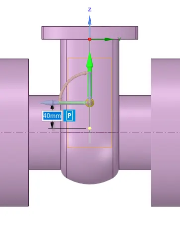
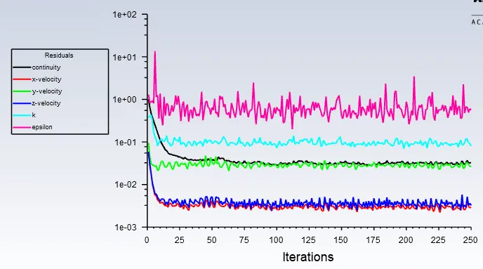
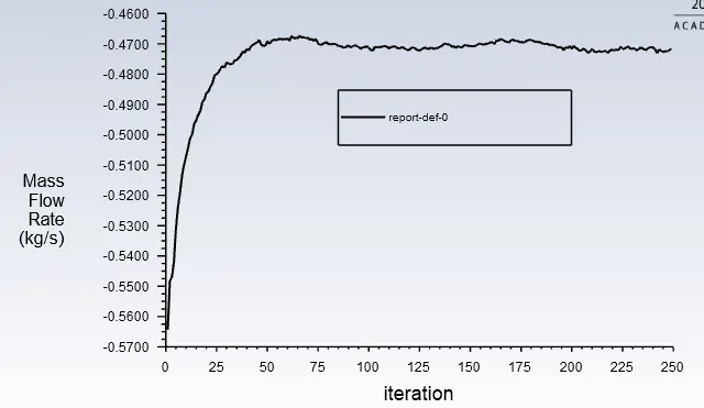
Case 4: Gate Disc lift = 40mm
Residual plots
Mass Flow rate
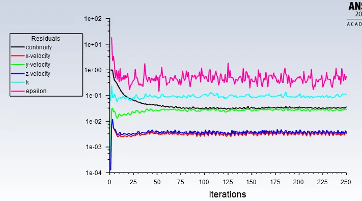
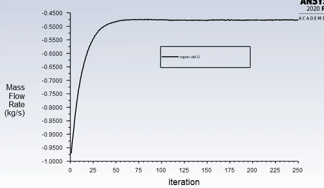
Case 5: Gate Disc lift = 50mm
Residual Plots
Mass Flow rate
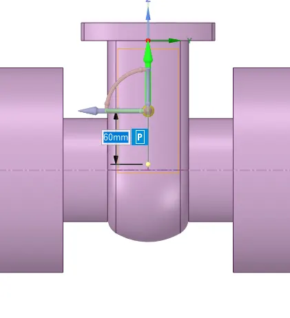
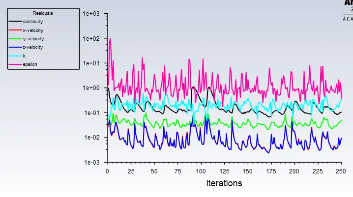
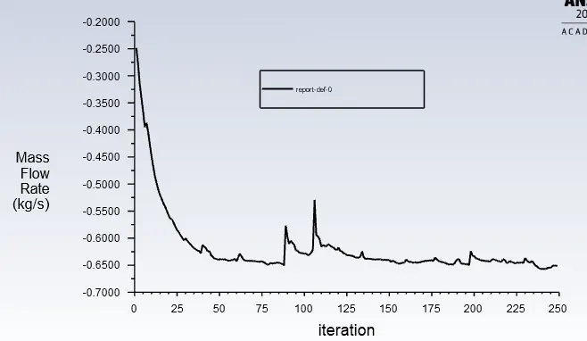
Case 6: Gate Disc lift = 60mm
Residual Plots
Mass Flow rate
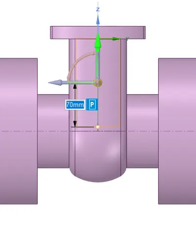
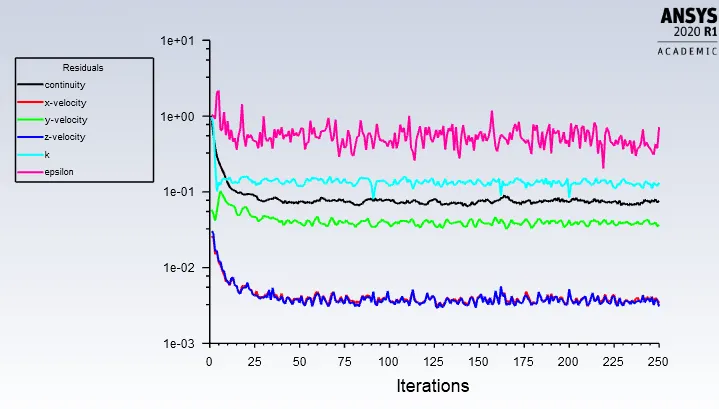
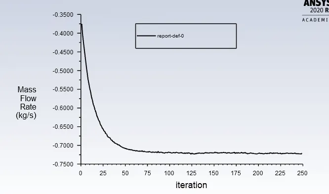
Case 7: Gate Disc lift = 70mm
Residual Plots
Mass Flow rate
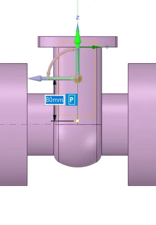
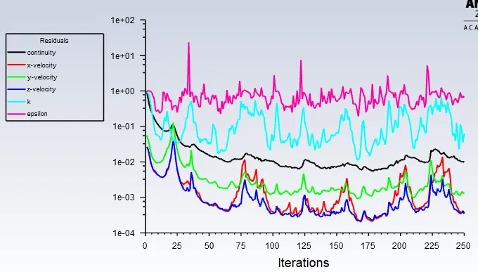
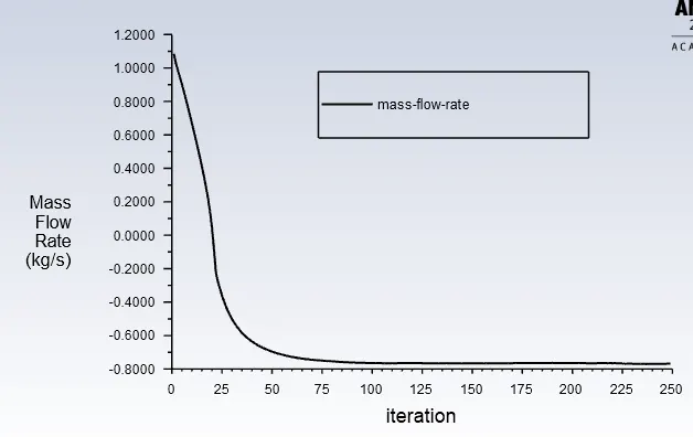
Case 8: Gate Disc lift = 80mm
Residual Plots
Mass Flow rate
Parametric Study
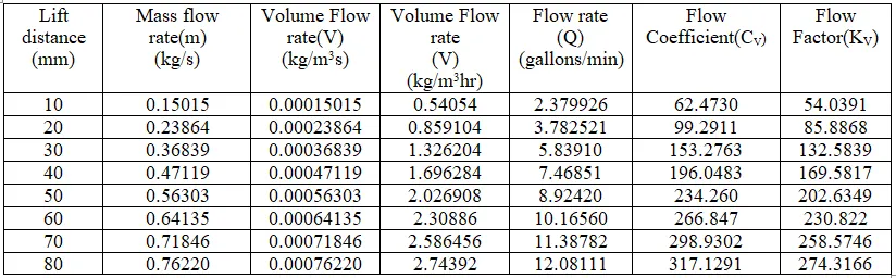
We take the lift as the input parameter and Mass Flow rate as the output parameter. The below table shows the Mass flow rate values for respective values of Gate Disc lift
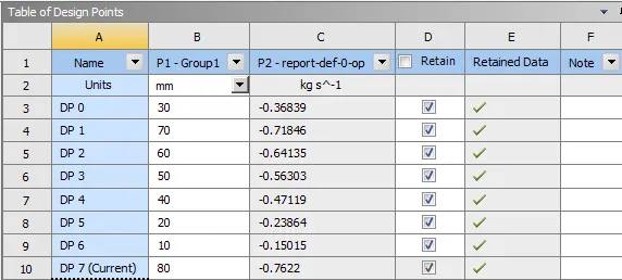
All the design points are updated and solution is completed
Flow Co-efficient
The flow coefficient of a device is a relative measure of its efficiency at allowing fluid flow. It describes the relationship between the pressure drop across an orifice valve or other assembly and the corresponding flow rate.
Mathematically the flow coefficient Cv (or flow-capacity rating of valve) can be expressed as :

- Q is the rate of flow (expressed in US gallons per minute) 1kg = 0.264172053 gallon
- SG is the specific gravity of the fluid (for water = 1)
- ΔP is the pressure drop across the valve (expressed in psi) 1Pa = 0.000145038 psi
The use of the flow coefficient offers a standard method of comparing valve capacities and sizing valves for specific applications that is widely accepted by industry. The general definition of the flow coefficient can be expanded into equations modeling the flow of liquids, gases and steam using the discharge coefficient.
Flow Factor
The metric equivalent flow factor (Kv; commonly used in Europe and Asia) is calculated using metric units :

Kv is the flow factor ( ). Q is the flowrate (expressed in cubic metres per hour [
 ]
]
SG is the specific gravity of the fluid (for water = 1), ∆P is the differential pressure across the device (expressed in [bar]).
Kv can be calculated from Cv using the equation

TABULATION:
The values of Flow Coefficient and Flow Factor for different Gate disc lift position are tabulated as below
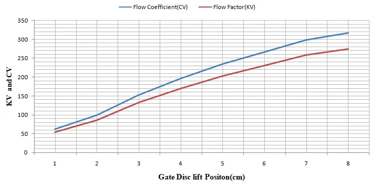
The variation of Flow Coefficient and Flow Factor with respect to Gate Disc lift postion is shown in the below plot
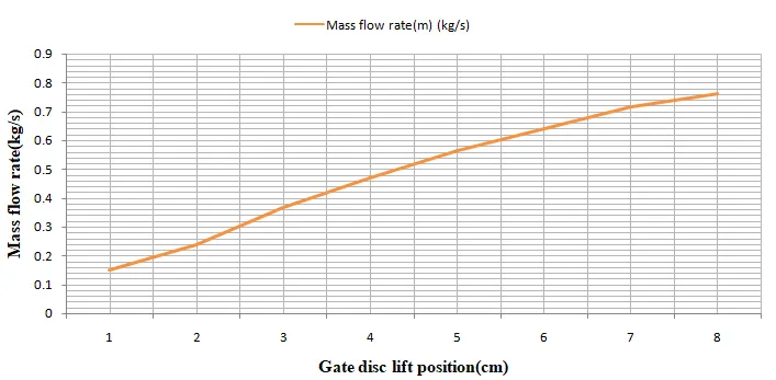
The variation of Mass flow rate with respect to Gate disc lift position is shown in the below plot
Observations:
It is found that increase in the gate disc lift increases the mass flow rate. As the gate disc is opened the velocity increases but the pressure decreases, hence the mass flow rate and the flow coefficient increases.