Gate Valve Parametric Study
Aim
The aim of the experiment is to undertake a parametric study using a gate valve opening from 10% to 80%.
Objectives of the study
- Obtain the mass flow rate at different design points.
- Obtain the flow coefficient and flow factor
- Plot the graph for different flow coefficient and flow factor
Gate Valve
A gate valve, also known as a sluice valve, is a valve that opens or closes by lifting or closing a barrier (gate) out of the path of the fluid.Gate valves are essentially of a flat or wedge-shaped gate that can be lowered into a seat to seal off the line or raised into an external recess so that the full area of the line is open.
They are one of the most commonly used valves, and are primarily used to permit or prevent the flow of liquids.
Gate valves can be used in demanding environments such as high-temperature and high-pressure environments. They are often used in:
- Power plants
- Water treatment
- Mining
- Offshore applications
Gate valves are also known as knife valves, slide valves, sluice valves or linear motion valves.
Experimental setup
The model used of the study undertaken is a gate valve with an initial rise of 10mm which can be seen the figure
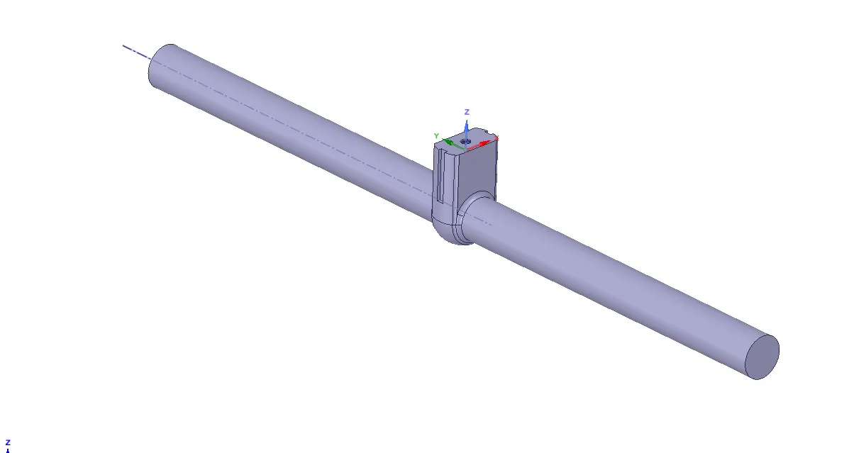
Figure1 : The gate valve model used for parametric study
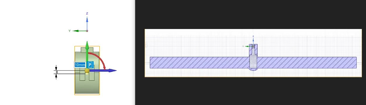
Figure 2 : Initial rise of 10mm in the gate valve
The parametric study option is enabled in the space claim and is a meshing with a size of 5mm is carried out.
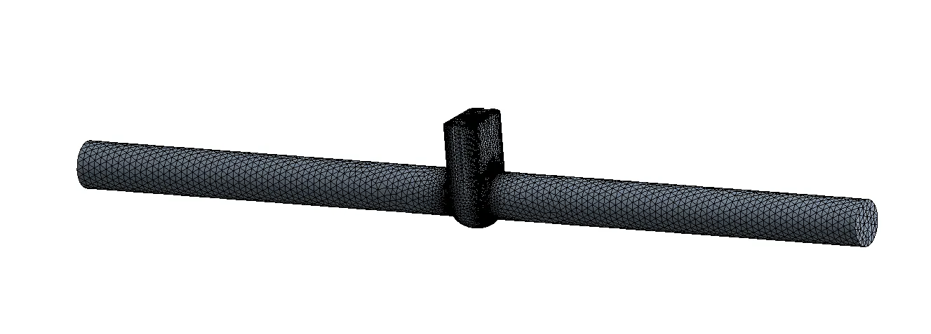
Figure 3 : Meshed model of the gate vale
The setup is then analysed using the following solver setting
Analysis type: Steady state
Gravity: Z=-9.81 (Gravity is enabled in the Z direction as the flow of water moves downwards when there is an opening in the gate valve)
Solver: Pressure-based
Model: K-omega sst
Material: Water-liquid (obtained from fluent material data base)
No of iteration: 400
Residual plot and Mass flow rate
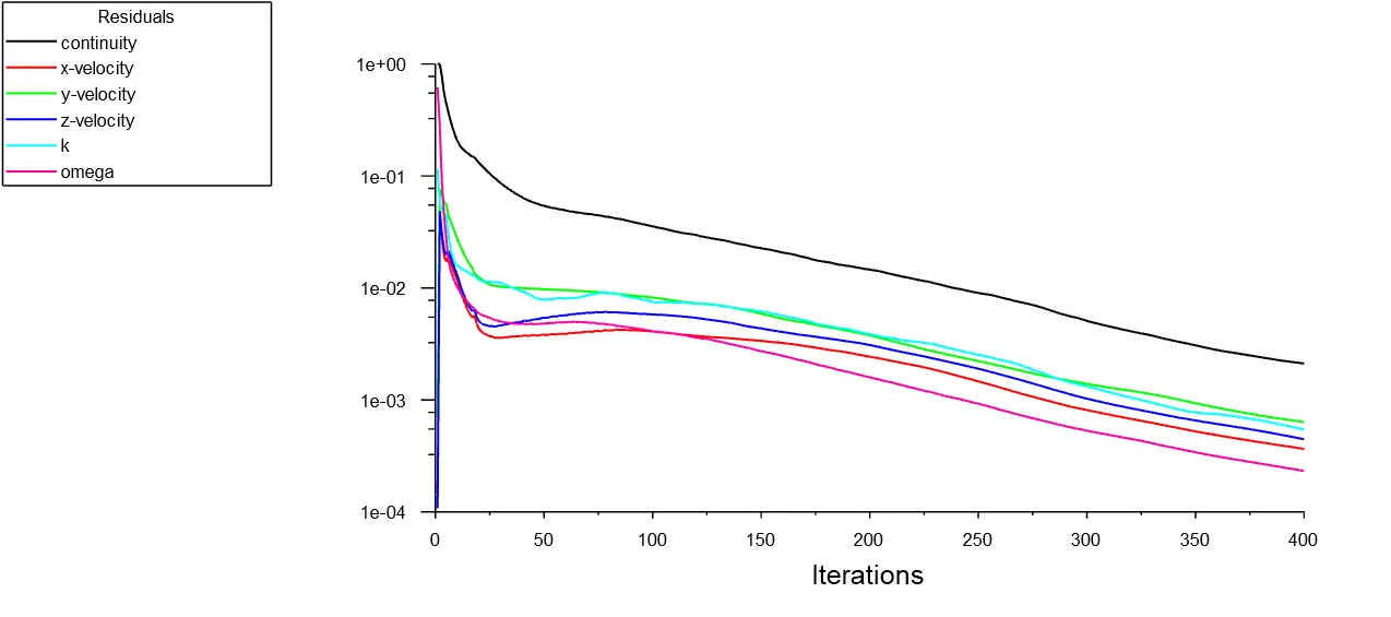
Figure 4 : Residual representing the convergence of the model
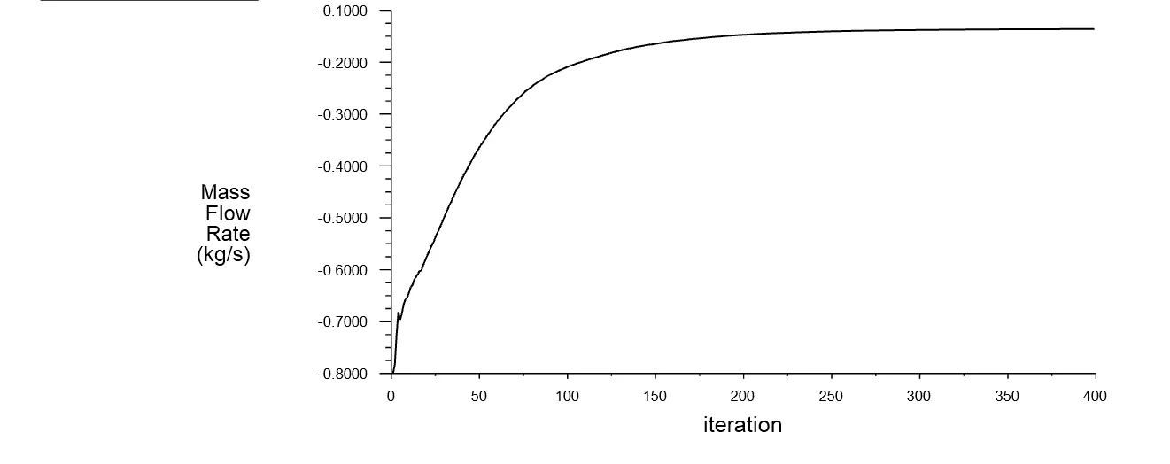
Figure 5 : Plot representing the mass flow rate at the outlet
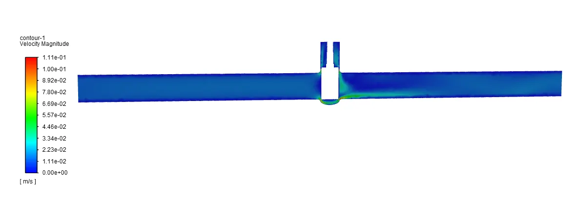
Figure 6 The velocity contour for a gate rise for 10mm
Mass Flow rate at different gate valve rise
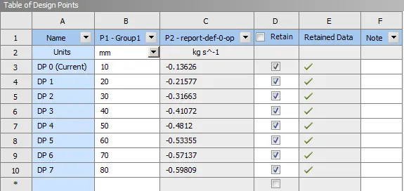
Table 1 Mass flow rate at different gate valve rise
Note: The negative sign in the mass flow rate value indicates that liquid is flowing outside.
Flow Co-efficient
Flow coefficient of a device represents the ease for a fluid flow to pass through the device. High flow coefficient of a device such as restriction orifice or a control valve indicates low resistance to the passage of flow. Similarly, low coefficient indicates higher resistance to the passage of flow and high pressure drop for a given flow.
Why You Should Care
Knowing and understanding your Cv can help you in a number of ways:
- Quickly compare different brands of valves and their flow capacities
- Help to select a valve that is the right size (and not oversized) for the application
- Quickly understand how the valve you select will have an effect on the pressure in your system
Determination of the Flow co-efficient and Flow factor
Mathematically flow co-efficient can be expressed as
Cv =Q√(SG/∇p)
where:
Q is the rate of flow (expressed in US gallons per minute),
SG is the specific gravity of the fluid (for water = 1),
ΔP is the pressure drop across the valve (expressed in psi).
Similarly, the Flow factor can be calculated using the equation
Kv = 0.865 (Cv)
Note: A Flow Factor (Kv) is the flow coefficient in metric units that is defined as the flow rate in cubic meters per hour (m3/h) of water at a temperature of 16ºC with a pressure drop across the valve or any other restricting device of 1 bar.
Calculation of flow co-efficient and Flow-factor
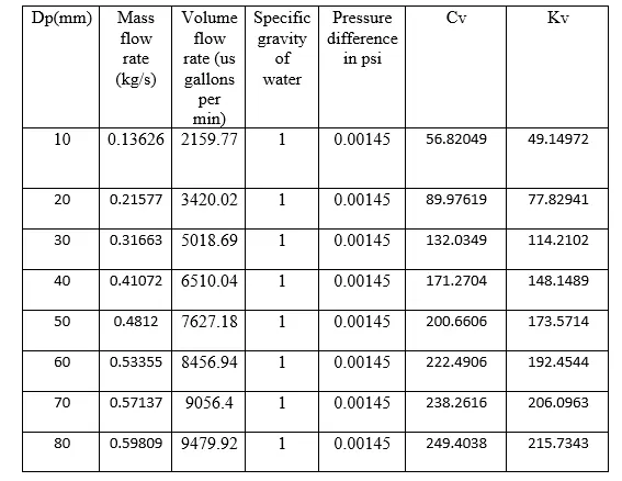
Table 2 Calculation of Cv and Kv
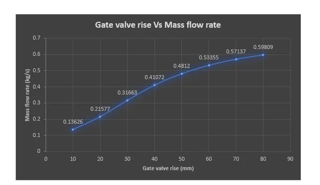
Plot 1 plot of gate valve Vs Mass flow rate
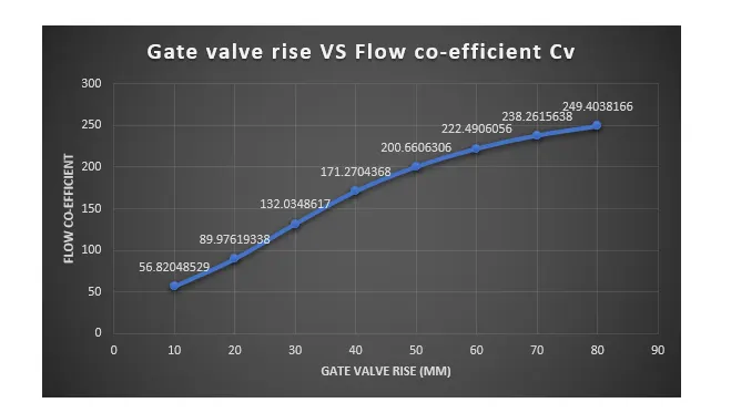
Plot 2 plot of gate valve Vs Flow co-efficient
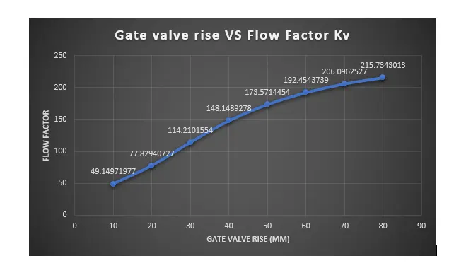
Plot 3 plot of gate valve Vs Flow factor
Discussion on the Results
- From plot 1 we could clearly identify that the mass flow rate increases as the gatve valve is rised.
- The flow co-efficient aswell indicates the increases in the flow rate as the gate valve rises, which could be seen in the plot 2.
- As the definition of Cv the larger the opening of the valve the larger would be the Cv which can been seen from the results.