Frontal crash Analysis using Hypermesh
Aim:
To run and analysis a Frontal crash with the BIW component add the mass up to 700kg and run the crash with given parameters.
Objective:
Frontal crash-BIW
- Check unit system and either follow[Mg mm s] or [Kg mm ms].
- Create an appropriate interface, friction 0.2 and recommended parameters.
- Make sure of no penetrations and intersection.
- Correct rigid bodies if any issues.
- Create a rigid wall with friction 0.1.
- Compare the model weight with the full-scale 300k nodes model and use added masses to reach target weight 700kg while getting CG about the required range.
- Initial velocity 35 mph.
- Use model checker to ensure good quality.
- Time-step :0.5 to 0.1 microseconds.
- Run 80 ms.
- Sectional force in the rails at the location of indicated nodes.
- The axial force received on the rails from the bumper.
- Shotgun cross-sectional forces.
- A pillar cross-section.
- Acceleration curve received on the accelerometer at base of B pillar (on B pillar rocker).
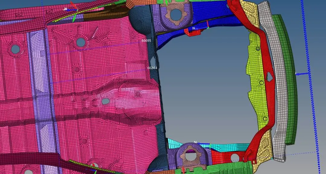
- Intrusions on the dash wall 66695,66244.
Introduction:
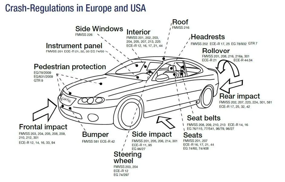
Explicit dynamics:
- Explicit dynamics approach is used for solving high deformation and high energy producing models.
- Used to determine the dynamic response of a structure due to stress wave propagation, impact or rapidly changing time-dependent loads.
- Momentum, Non-linearity effects and inertial effects are usually taken into consideration.
- The explicit method has many pros like Conditional stability, Dynamic and shock problems, Element by element calculation, Relatively low in cost, Timestep is too small and High Robustness
Equation:
`[M] {(d^2u)/(dr^2)}+C{(du)/dt}+K {U}={Fext(t)}`
Where,
M= Mass matrix
C= Damping matrix
K= Stiffness matrix
Crash Testing Requirements:
Regulatory testing: FmVss,ECE,AU,JS,BNVSAP
Consumers testing: NCAP
- The regulatory test provides an answer to the question, whether the car passes or fails If injury recorded in dummy is less than the standard value then it is said to be passed.
- Consumer testing will give a star rating based on the injury results. They will also give a rating based on individual component performance from the car.
- The results from the above testing drive the overall business decisions as well.
Type 7, node to surface contact:
1. A general-purpose interface and can simulate all type of impact between a set of nodes and a master surface.
2. Non-oriented and slave node can belong to the master surface- Hence auto-impact possible.
3.Automatic node to surface contact interface using the penalty method with variable stiffness.
4.A gap is defined around the master segment and the slave node.
5. Resistive forces are applied to keep slave nodes out of the contact gap.
Procedure:
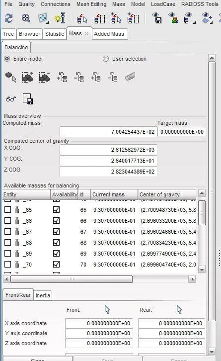
1. In this case, we have to add mass to the given model and then set the given parameters.
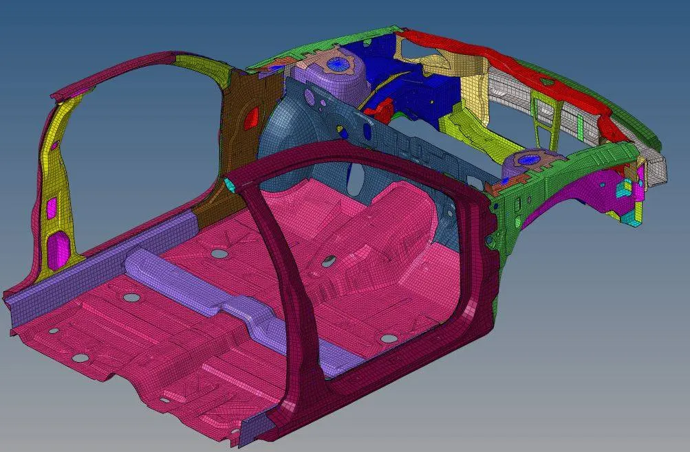
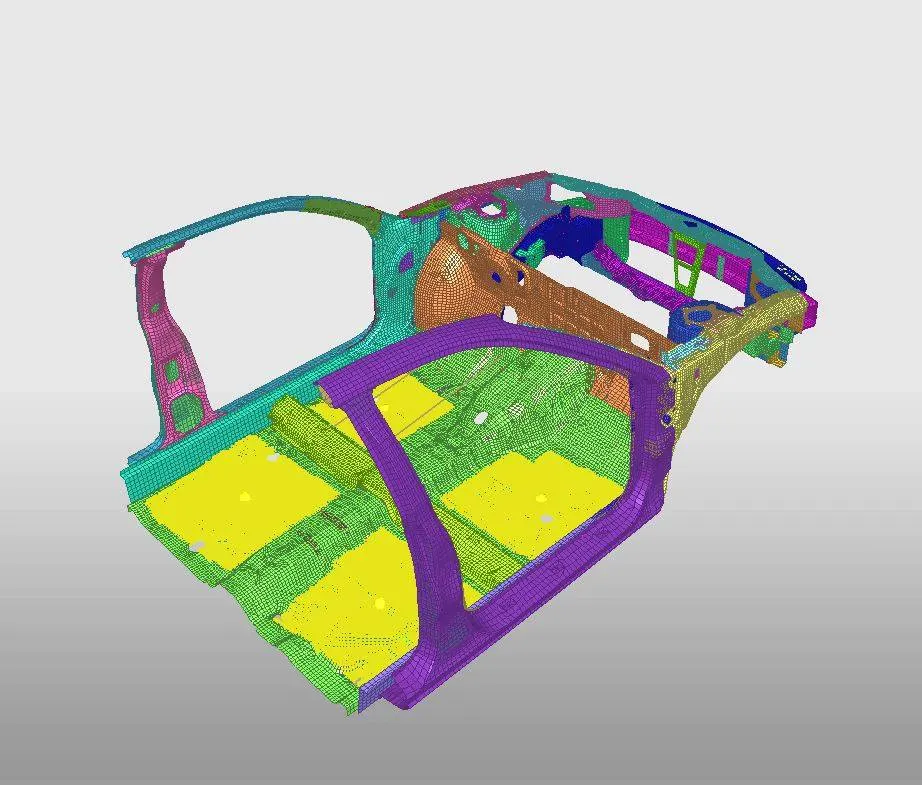
Add mass to the model up to 700kg while getting CG about the required range.
The red dot represents COG point which is at the centre of the car by distributing the mass evenly.
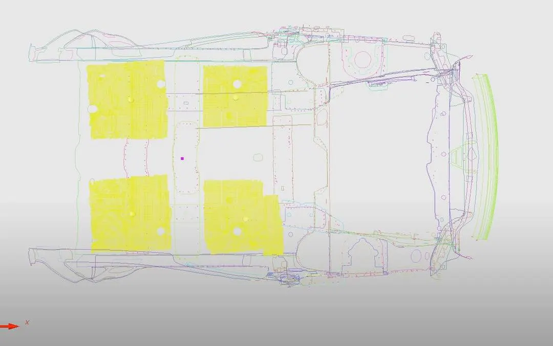
In this mass tab, we can view the total mass added to the BIW model.
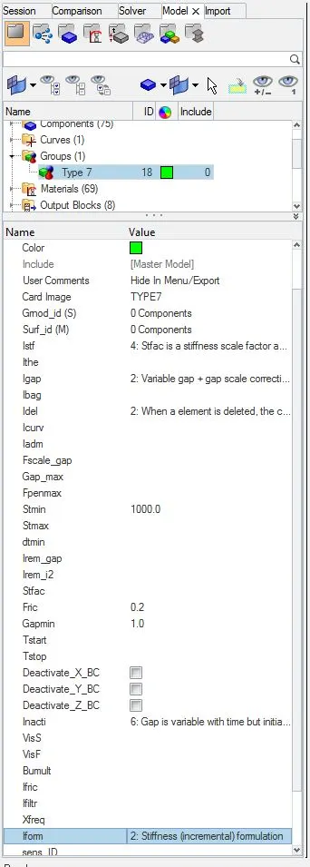
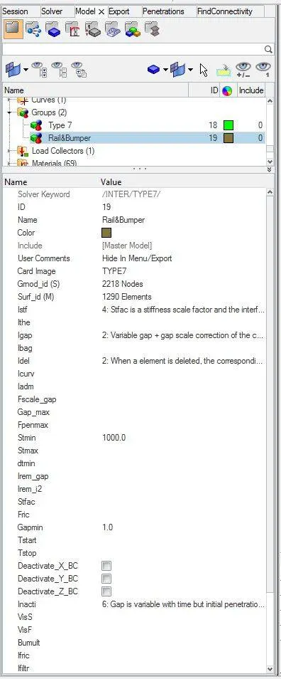
2. To Create the contact interface Type 7 with friction 0.2 and recommended parameters.
Igap=2 (set the variable gap to take into account the true distance between parts.)
Gapmin = 0.5 mm (Specify minimum thickness of the model to avoid numerical issues.)
Inacti = 6 (Remove initial penetration where possible. Elsewhere, reduce to less than 30% of the defined gap value and adjust the gap with Inacti)
Istf= 4 (Set stiffness of interface based on the softer of master and slave)
Stmin = 1000N/mm (specify a minimum stiffness in the contact to avoid too soft contact)
Idel =2 (Removes the slave node from contact because of element deletion)
Iform = 2 (Sliding forces are computed using stiffness parameters of the interface.Usually results in bigger time step)
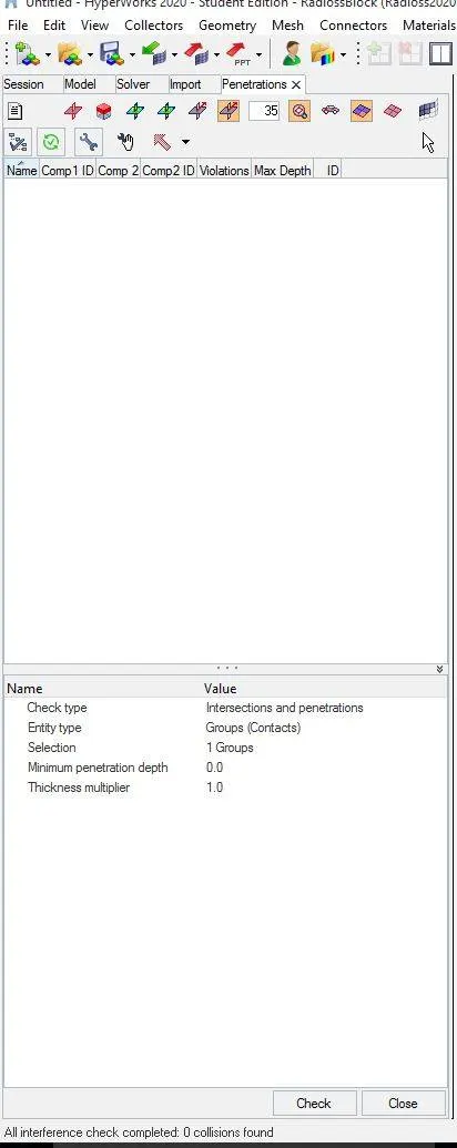
3. Now to check any penetration and intersection in the model.
The output of the run shows zero collision found.
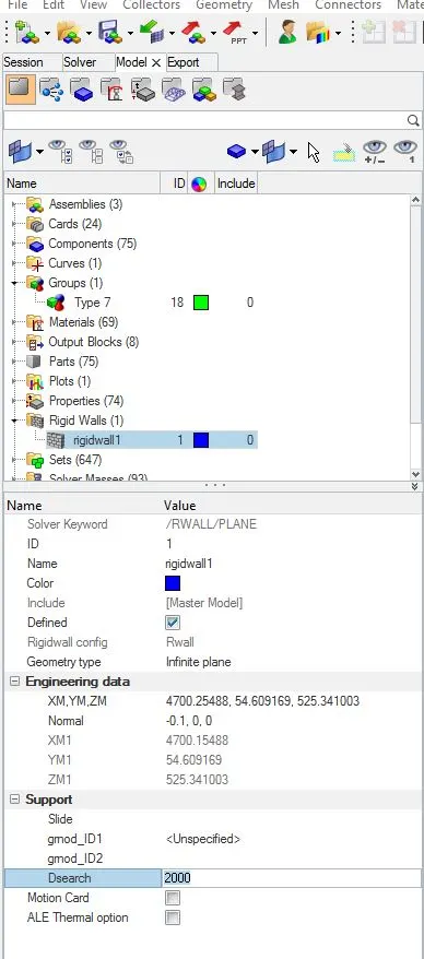
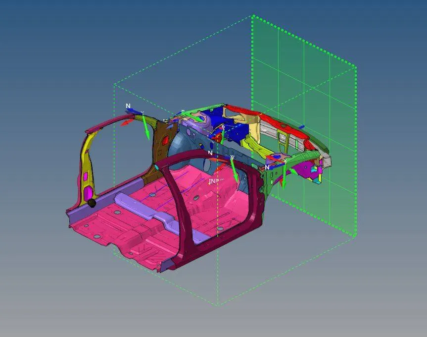
4. To create a rigid wall we have to create a rigid wall card in the model and mention the parameters for front crash the friction is set to 0.1, geometry type is set to the infinite plane and Dsearch is set as recommended.
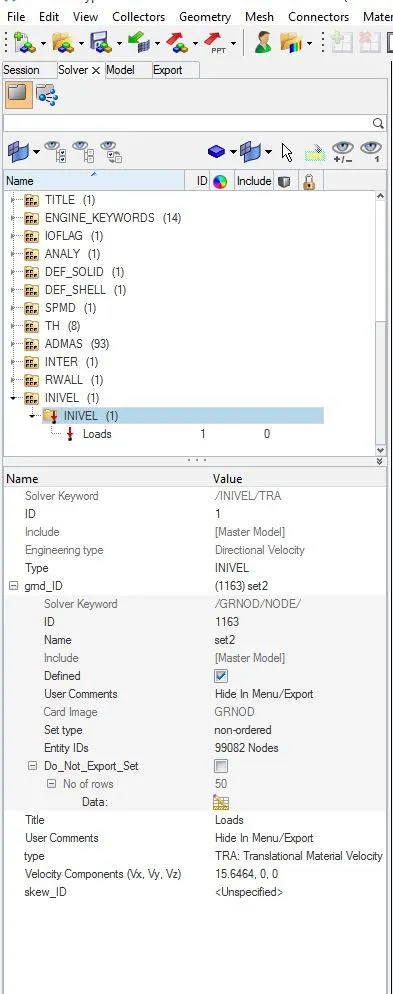
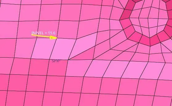
5. In solver create a new initial velocity card for the parameters create a new set in a set group and select the new set in gmd_ID. and for velocity, the units are in m/s so from the given 35 mph is converted to 15.64 m/s.
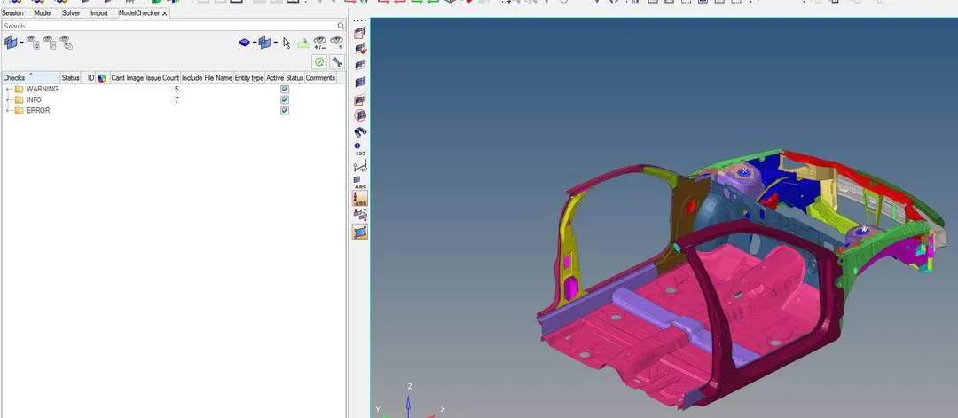
6. The model checker shows there are no errors in the model.
7. In Solver the Timestep DT/NODA is set to 0.0005.
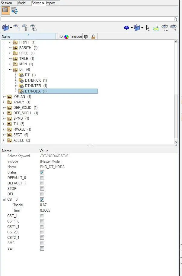
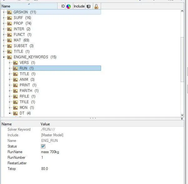
8. To set the run-time edit the engine run card Tstop as 80 seconds.
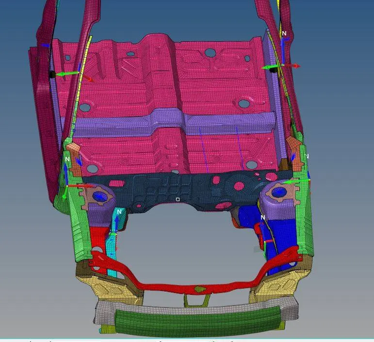
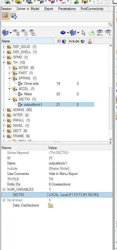
9. To get the output data on a particular part, Section is created along with the frame and added to the output block. Sections are created in Support rails, A-pillars and Shotguns.
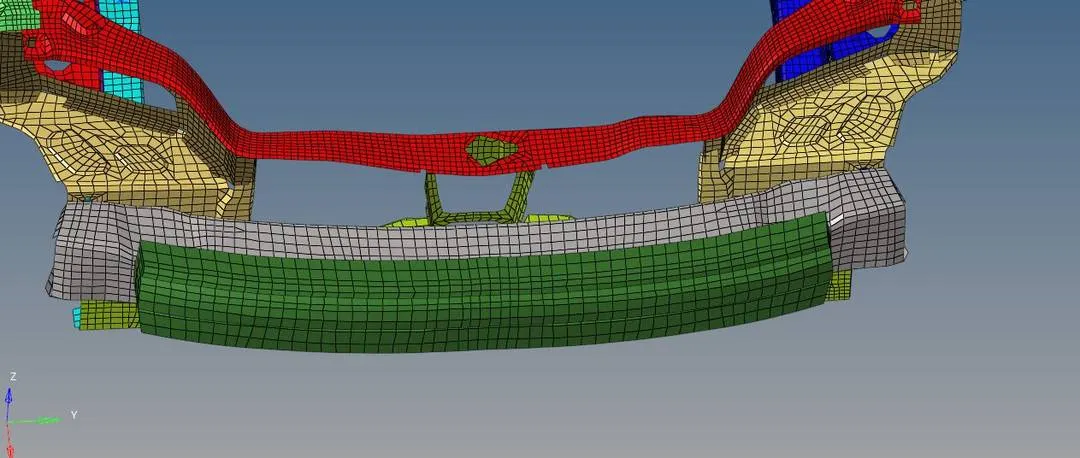
10. To get the output result Axial force received on the rails from the bumper. We have to create an interface between bumper and rails.
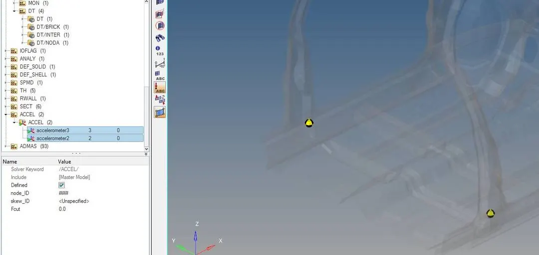
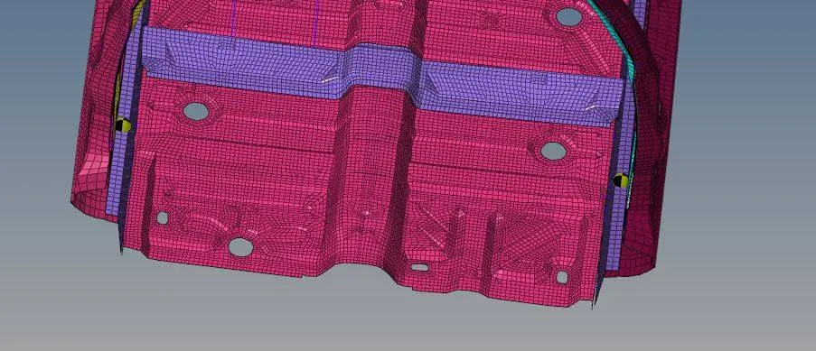
11.An accelerometer is created at the base of B pillar rocker to get Acceleration curve.
12. The compression distance is calculated by creating 1D springs on the given node 66695,66244.
13. To get the output results in the graph we have to create TH for all the new cards.
Result:
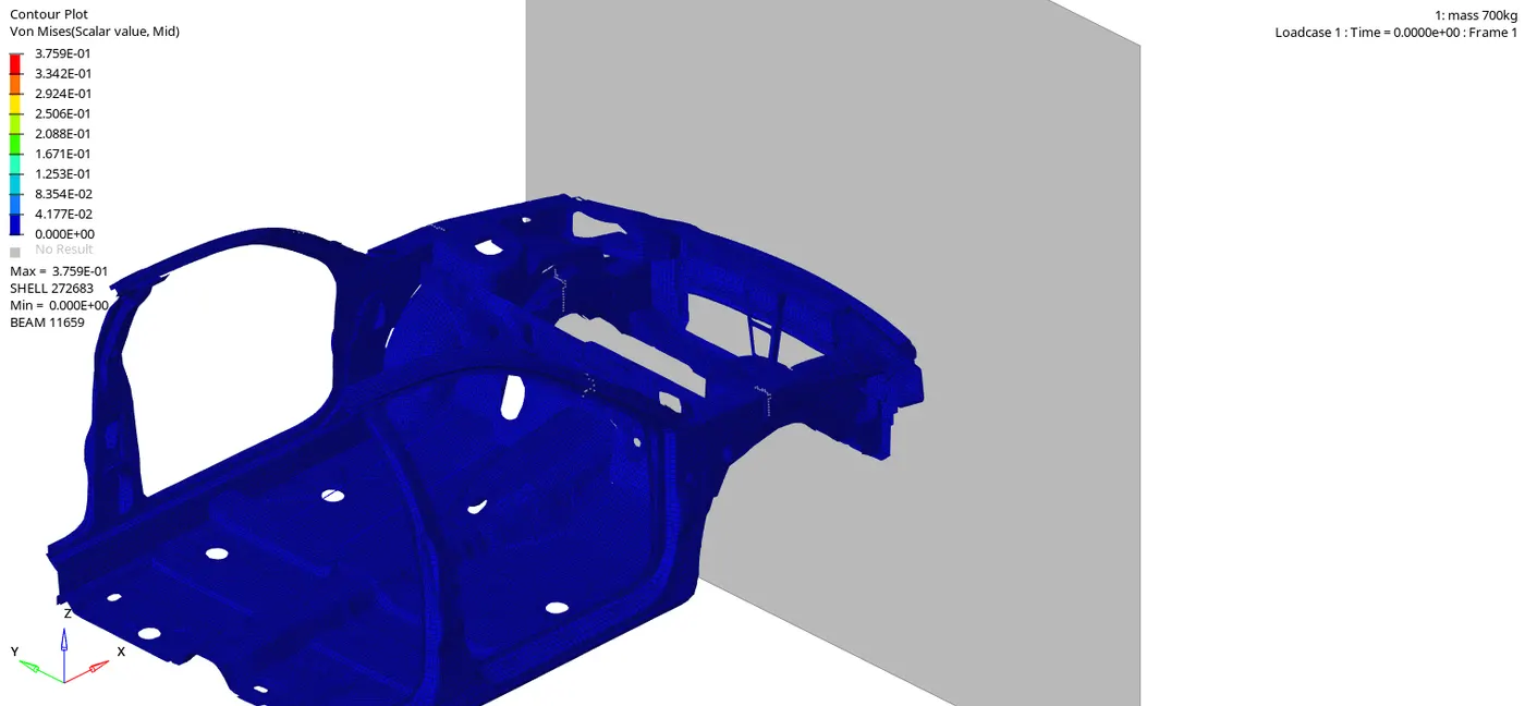
The car is moving at a velocity of 56.32 kmph which hits the rigid wall, due to this impact some parts get huge deformation as shown in the animation. The maximum stress is developed as 375.9 Mph in 80 s.
Internal and Kinetic energy:
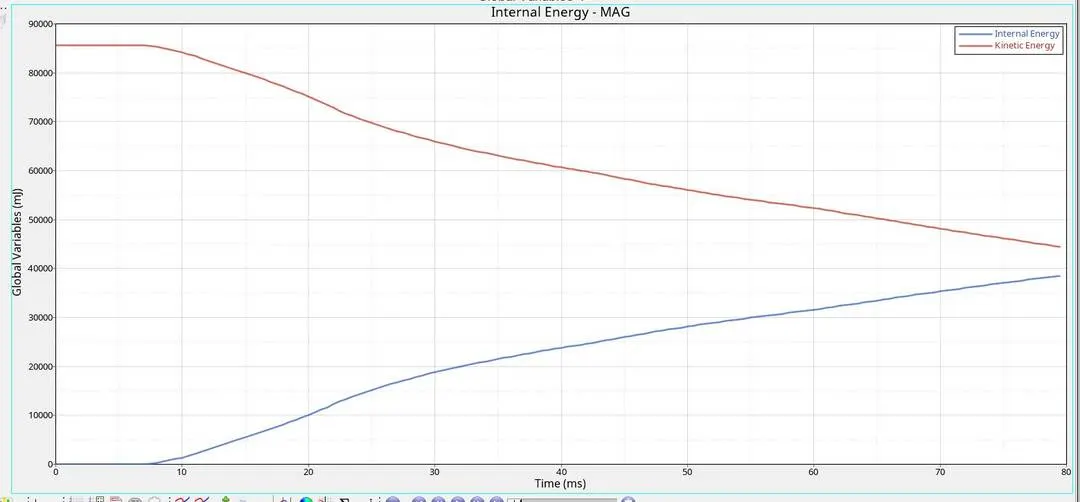
The kinetic energy is constant for 10s because the object is not in contact with the rigid wall. After 10s, the kinetic energy is decreasing from 85000 to 45000 due to frontal crash impact the internal energy increases from 0 to 39000.
Contact and Hourglass energy:
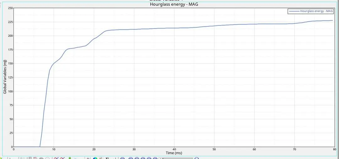
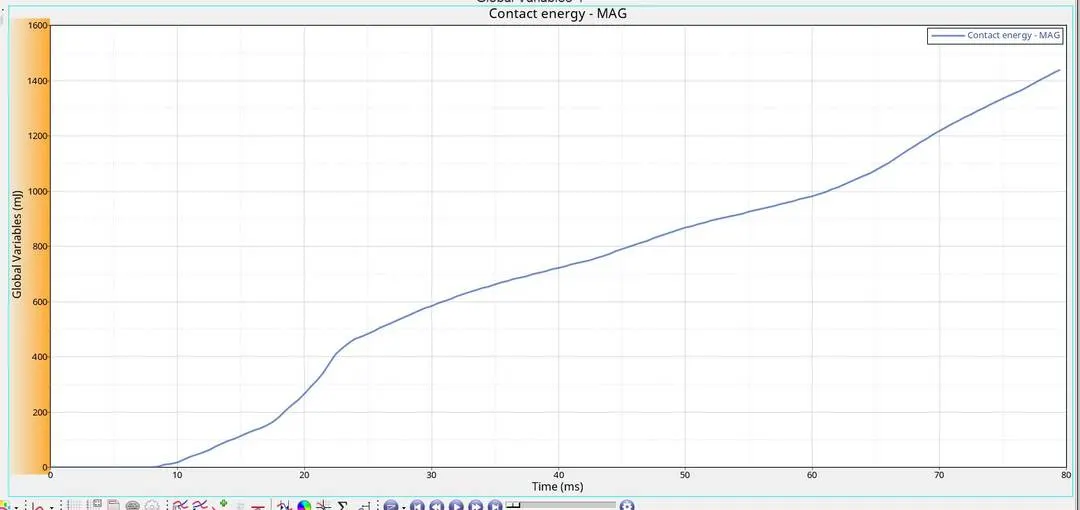
When the parts collide, The contact force transfer energy through the parts which intersect each other, and transfers energy between them. The maximum energy formed is 1420 J. The hourglass energy at maximum energy deformation of the elements is 225 J.
Total energy:
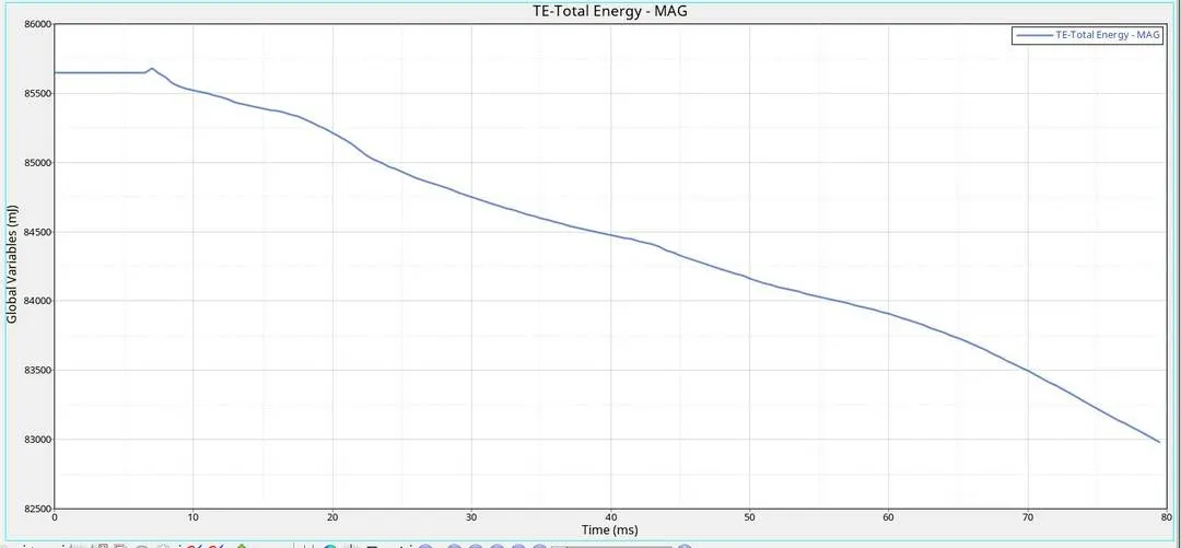
Total Energy=IE + KE + RKE + CE + HE (RKE-Rotational kinematic energy, CE-Contact ENery, HE-Hourglass Energy) and the total energy must remain constant or can decrease very slightly.
A pillar section force:
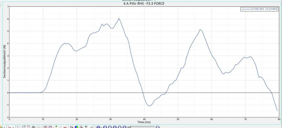
Sectional force on RHS A-pillar is 6 KN
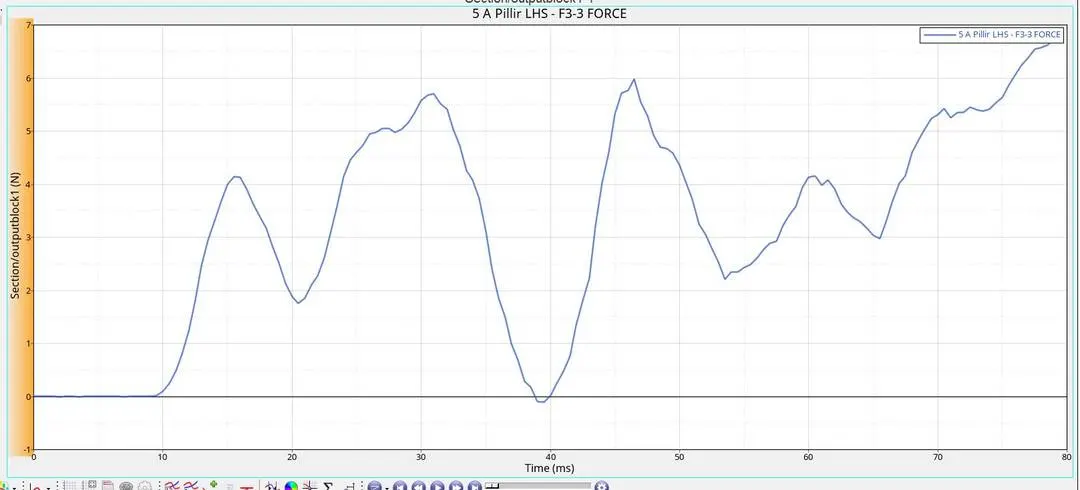
Sectional force on LHS A-pillar is 7 KN
A-pillar receives only 20% of the total force transfer remaining is transferred to the floor panel of the car that's why the section force of both pillars is less compared to other components.
Shotgun force:
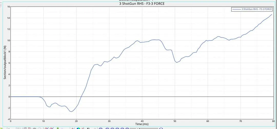
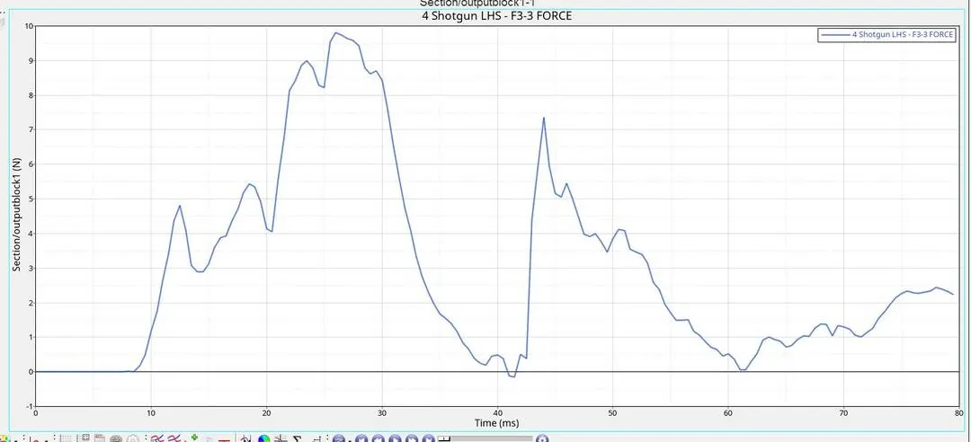
Section Force at Shotgun RHS is 14.4 KN
Section Force at Shotgun LHS is 9.9 KN
Generally, Shotgun is made of advance high strength material which is having high strength as well as high toughness, so that the shotgun absorbs all the force and deforms and buckles so that the energy transmission to the occupant area will be less.
The graph value is negative because the normal axis indicates towards the rigid wall, so as per the study we can consider by assuming as a positive value.
Rail Force:
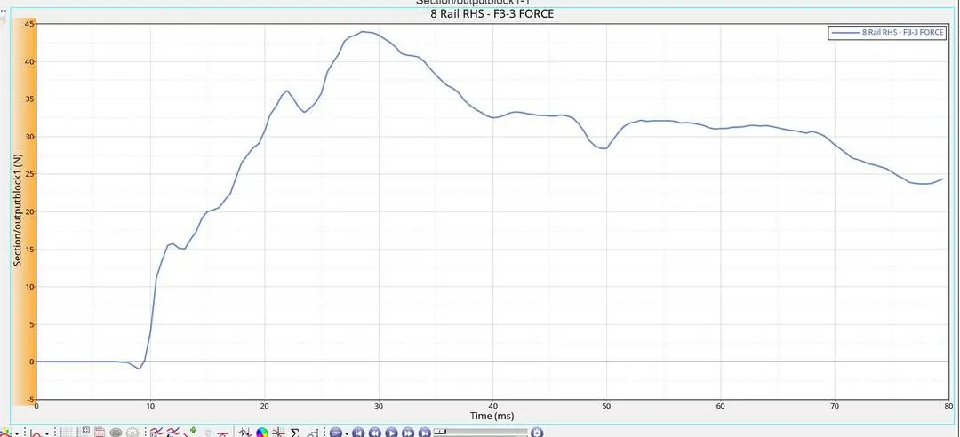
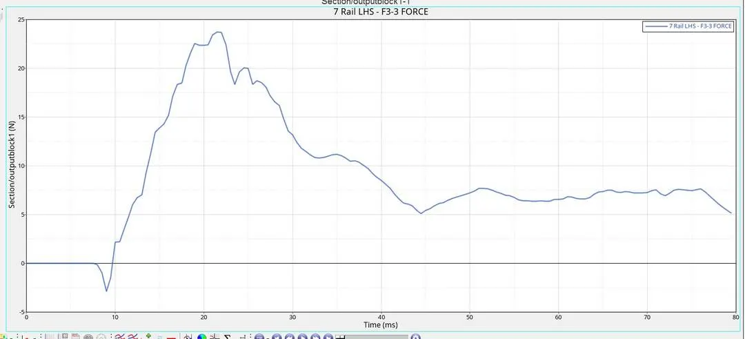
Section Force at RHS Rail= 44 KN
Section Force at LHS Rail= 24 KN
The Front rail absorbs around 45% of total energy during frontal impact as compared to sub-assemblies
Since the rail is behind the bumper, once the bumper is fully deformed the remaining force from the rigid wall, is transferred to rail component.
Axile force on Rail and Bumper:
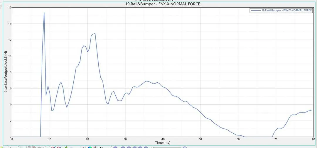
The Above graph shows the impact between bumper and rail where there is fluctuation due to force acting and mass distribution. The maximum force in the X direction is 15.2 KN.
Acceleration curve on B-pillar rocker:
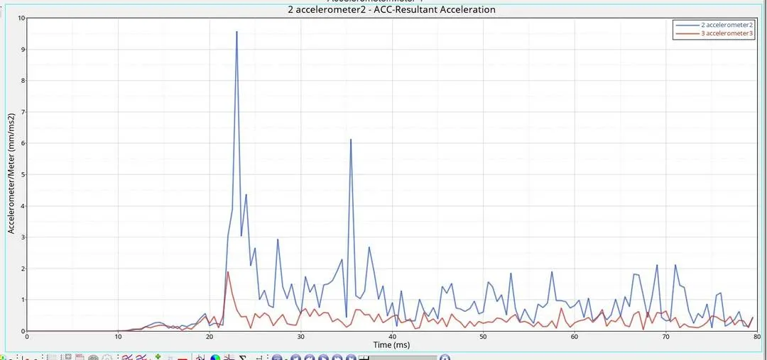
Accelerometer 2- RHS
Accelerometer 3- LHS
The maximum value of the acceleration on RHS is 9.6 mm/ms^2
The maximum value of the acceleration on LHS is 1.9 mm/ms^2
Intrusions on the dash wall with springs:
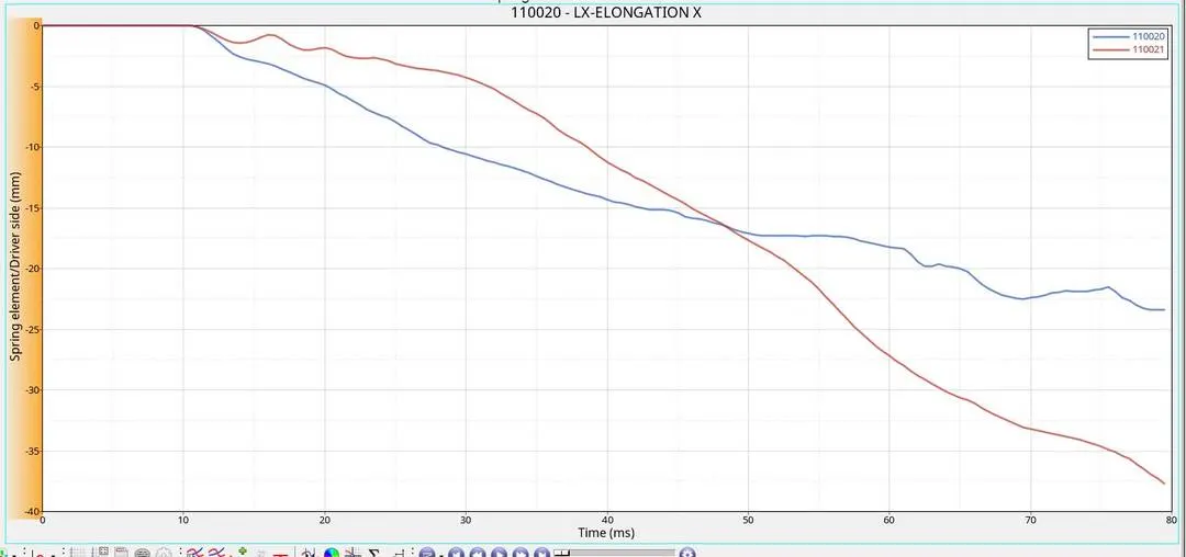
Spring at LHS on node 66695 = 37mm
Spring at RHS on node 66244 = 24mm
The displacement of two springs on the two-nodes is displaced this is due to the absence of components in the engine compartment.
The components in the engine compartment will absorb energy before transferring to dash wall since these components aren't there the force is directly transferred to the dash wall
By increasing the material grade and thickness of the dash wall component will increase the stiffness and reduce the intrusion.
Conclusion:
The frontal crash analysis is done with the student version of Hyperworks. The Improper meshing leads to some errors which are in an acceptable range.
We have obtained the value of the sectional force at the A-pillar, Shotgun, Front rails and have created type 7 interface between rail and bumper. Obtained the Intrusion on particular nodes and acceleration as well.
The bumper, rail and shotgun which are the component in the crash zone they absorb more energy and transfer energy to passenger section that's why a section of A-pillar has less force.
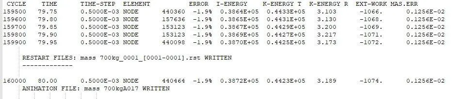
The energy error obtained as -1.9%, Mass error obtained is 0.1256e-02 No of cycles is 160000.
By improving the Components in the crash zone will help in protecting the occupants.
- The energy error and mass error are in an acceptable range.
- The sectional force in bumper to rail for both RHS and LHS plays an important role in absorbing the max impact.
- The shotgun design also plays an important role in keeping the impact less transmitting to the interior parts of the vehicle.
- The position of the centre of gravity of the vehicle is vital in the crashworthiness, so maintaining the weight balancing of the vehicle is the skill of design engineer.
- As we are using the half model and with added masses, if we can go for full vehicle body analysis then more realistic results can be obtained.