Frequency Analysis of a rotating shaft
Aim: Understanding frequency analysis of a rotating shaft.
Objective:
- Create a 3D Model of a shaft in SolidWorks.
- Perform a frequency analysis and explain the results.
Theory:
Every structure has the tendency to vibrate at certain frequencies, called natural or resonant frequencies. Each natural frequency is associated with a certain shape, called mode shape, that the model tends to assume when vibrating at that frequency.
When a structure is properly excited by a dynamic load with a frequency that coincides with one of its natural frequencies, the structure undergoes large displacements and stresses. This phenomenon is known as resonance. For undamped systems, resonance theoretically causes infinite motion. Damping, however, puts a limit on the response of the structures due to resonant loads.
If our design is subjected to dynamic environments, static studies cannot be used to evaluate the response. Frequency studies can help us avoid resonance and design vibration isolation systems. They also form the basis for evaluating the response of linear dynamic systems where the response of a system to a dynamic environment is assumed to be equal to the summation of the contributions of the modes considered in the analysis.
Resonance is desirable in the design of some devices.
A real model has an infinite number of natural frequencies. However, a finite element model has a finite number of natural frequencies that is equal to the number of degrees of freedom considered in the model. Only the first few modes are needed for most purposes.
The natural frequencies and corresponding mode shapes depend on the geometry, material properties, and support conditions. The computation of natural frequencies and mode shapes is known as modal, frequency, and normal mode analysis. Some examples of first five modes of frequencies are shown below in chronological order from mode-1 to mode-5.
Problem Statement:
A 3D CAD model was given which was basically a rotating shaft supported over two bearings. Over this model, frequency analysis was to be done and first 5 frequencies were to be calculate. The 3D CAD model looks as below:
Problem Solution:
Based on above model, as dimensions were not given, the dimensions were assumed and the model was made as shown below:
Performing Frequency Analysis:
To perform frequency analysis:
- Create a frequency study. Right-click the top icon in the Simulation study tree and select Properties. Define the Properties of the study to set the number of frequencies.
- The program calculates the lowest five modes by default. If the program detects rigid body modes, it lists them first. In this case, you need to increase the number of modes to let the program calculate the non-rigid body modes.
- Define material for each solid, shell, and beam. To define a material for a solid, shell, or beam, right-click its icon in the Simulation study tree and select Apply/Edit Material.
- Note that density is a required material property.
- Define appropriate restraints, if applicable.
- Both the FFEPlus and Direct Sparse solvers detect rigid body modes automatically for unrestrained or not adequately supported models. Rigid body modes, if detected, are counted among the requested number of modes.
- Define loads if desired.
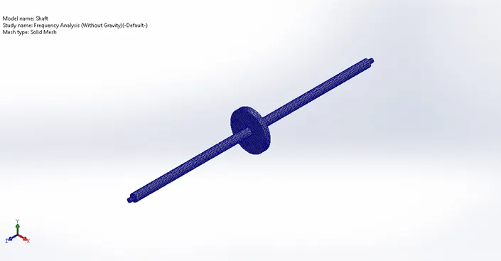
- Mesh the model and run the study.
- View the results:
- Double-click an icon in a Results folder to display the associated plot.
- Right-click the Results folder and select List Resonant Frequencies to list the requested number of resonant frequencies in addition to any rigid body modes.
- Right-click the Results folder and select List Mass Participation to list the mass participation of the calculated modes.
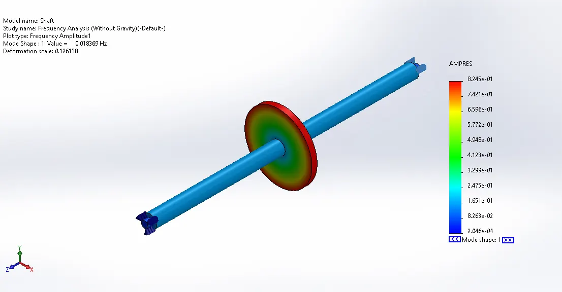
- To define a mode shape, right-click the Results folder and select Define Mode Shape/Amplitude Plot.
- To animate an active plot, right-click its icon or right-click in the graphics area and select Animate.
Following is the summary of the performed frequency analysis for the given model:
Connector DefinitionsPin/Bolt/Bearing Connector
|
||||||||||||||||||||||||||||||||||||||||||||||||||||||||||||||||||||||||||||||||||||||
Mesh informationMesh information - Details
|
||||||||||||||||||||||||||||||||||||||||||||||||||||||||||||||||||||||||||||||||||||||
Study Results
Mode List
|
||||||||||||||||||||||||||||||||||||||||||||||||||||||||||||||||||||||||||||||||||||||
Conclusion:
- Frequency analysis was carried over the model and first 5 modes of frequency were calculated.
- In order to avoid the shaft to rotate violently, care must be taken that the rpm of rotor don’t come closer to above tabulated frequencies.