Foundation Design using SAFE
Ans1.
1. From week 11
.Square footing for a column size of 400x 400
.Compression axial load for the load combination of (1.5DL+1.5LL) is 2000 KN
.The scale bearing capacity is 150 KN/m^2 at a depth of 2m blow E.G.L
Assume M25 concrete grade
2.Data required for safe analysis and design
Unfactored load =2000/1.5=1333.3 KN
I dont have any idea devide the given load how much for ded and how much for live
So im going to devide by 2
Dead load breackup=1333.3/2=666.7 KN
Live load breackup=1333.3/2=666.7 KN
3. Sub grade modulas for the soil = (safe bearing capacity X factor for ultimate) /maximum settlement
=150x3/0.05=k=9000 KN/m^3
Rebar yield strength (Fy)=500 N/mm^2
Rebar ultimate strength (Fu)=575 N/mm^2
Elastic modulus of M25 concrete=25000 N/mm^2
4. Then just go to the SAFE software
go to new and set the display unit and simpaly click ok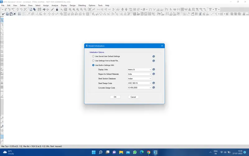
Then you have a window and go to select single footing and fill the footing size and footing slab thickness and sub grade modulas dead load and live and size of the column and click ok and ok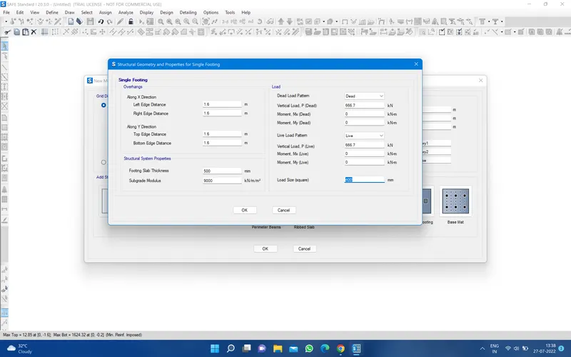
Then go to and defin material property and addd gthe new material rebar and concrete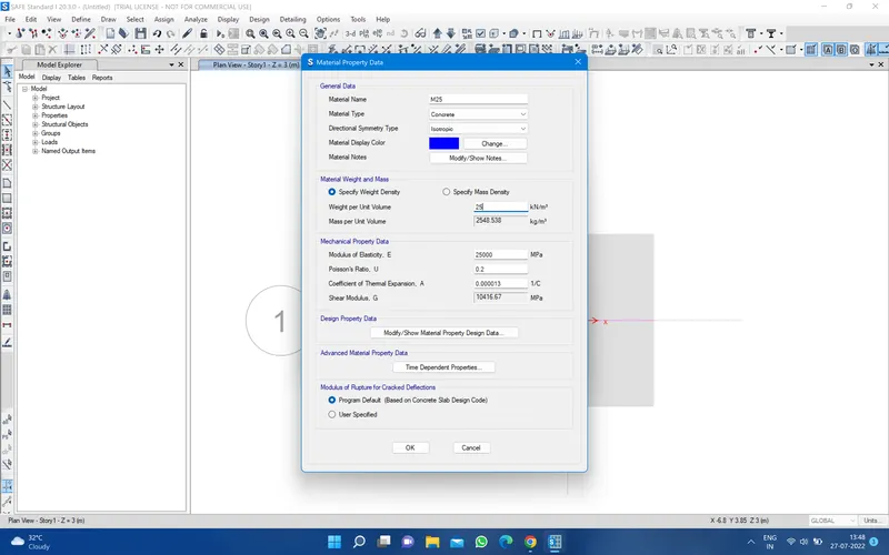
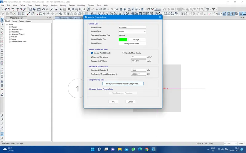
Then go to define section property and slab property and define footing and stiff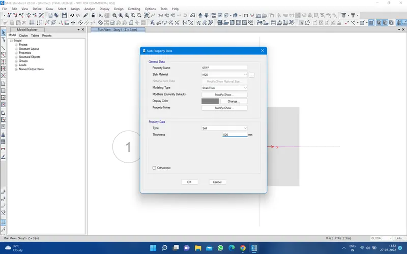
Then go to spring property and go to area spring and define soil property 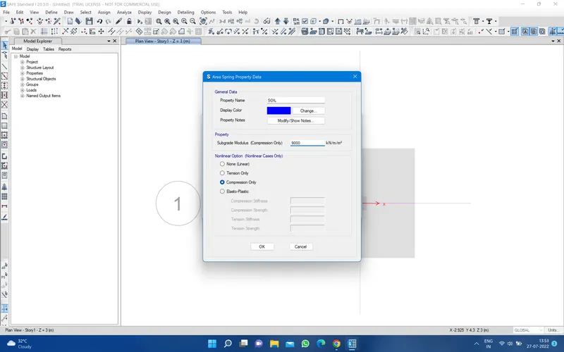
Then go to define the load case 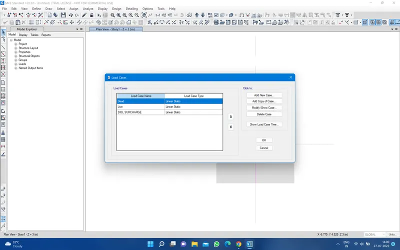
and define the load combination 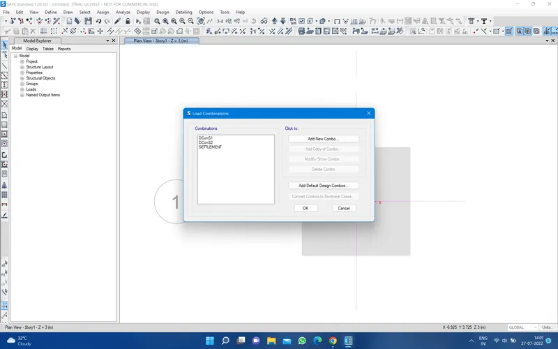
then assign the soil for that just go to assign and go to shell then go to area spring and apply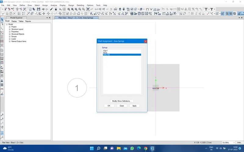
now rur the analysis 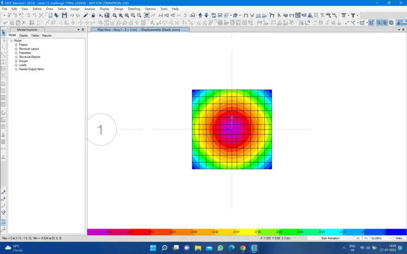
* Check need to performed in safe analysis
1.safe bearing capacity under survice load for that just go soil pressure and the combo and apply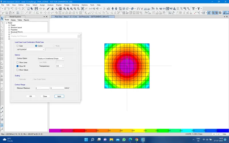
The maximun soil pressure is 226
2.settlement under survice load for that just go to so deform shape and select the combo and setelement and apply 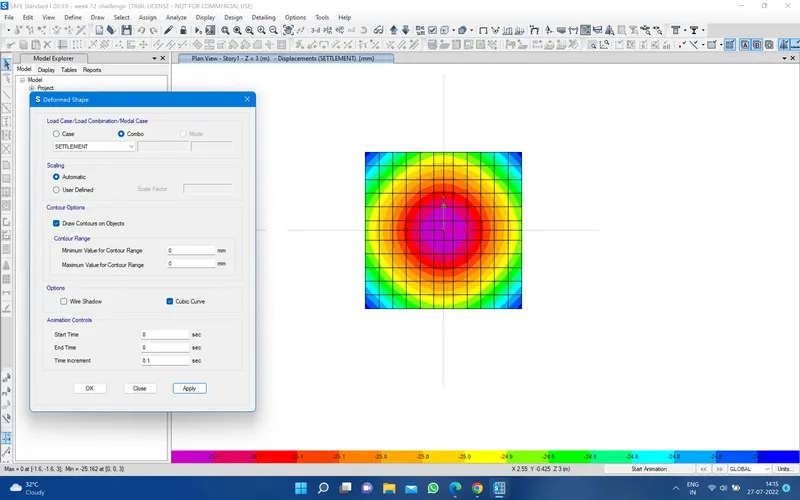
that soil pressure is less then allowable soil pressure hence okey
3. two way shear check just click button show punching design 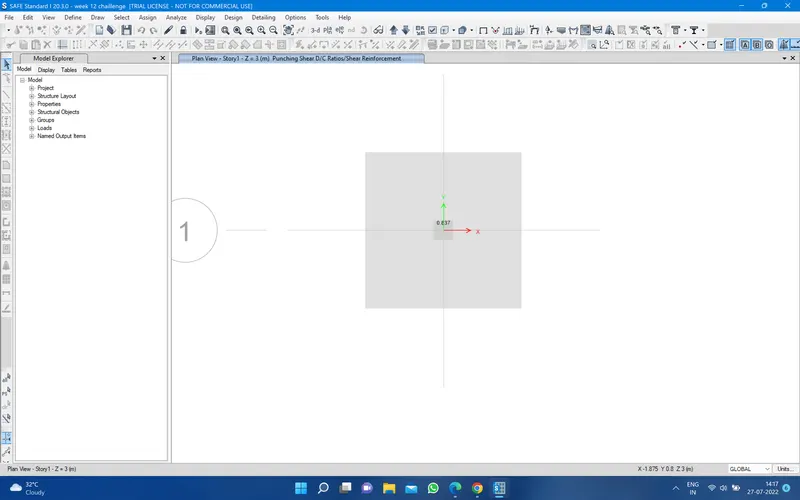
it is less then 1 hence okey
4. Ultimate banding movement frist switch on the design strip then go to show strip force then select the decon 1 or decon 2 and layer a and b and ok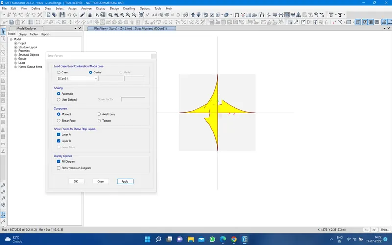
and shear force 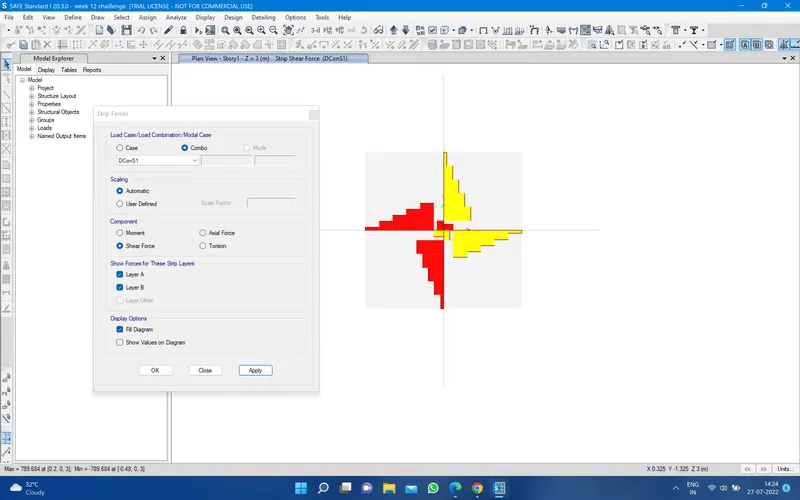
5. Flextural reinforcement design fro footing slab for that just go to show slab design and set as required and apply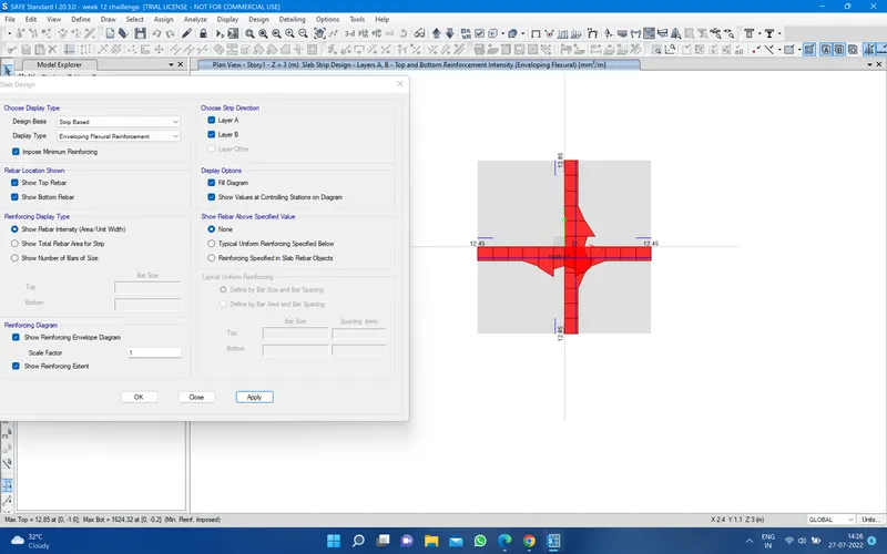
Ans2. 1. Data Required for SAFE analysis & Design
Unfactored load =1175 KN
Dead load breakup =1175/2=587.5 KN
Live load breakup=1175/2=587.5 KN
Point spring of pile AE/L= A=`pi/4*d^2`
=19634x25000/16000=306796 KN/m
K for safe analysis =306.8 KN/mm
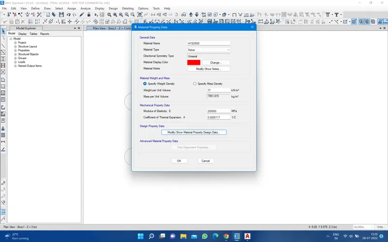
2. Rebar yield strength (Fy) =500 N/mm^2
Rebar ultimate strength (Fu)=575 N/mm^2
Elastic modulus of M25 concrete =25000 N/mm^2
3. Number of pile required
=Unfactored load with safe weight addition /individual pile capacity
=1175*1.1/200=6.5
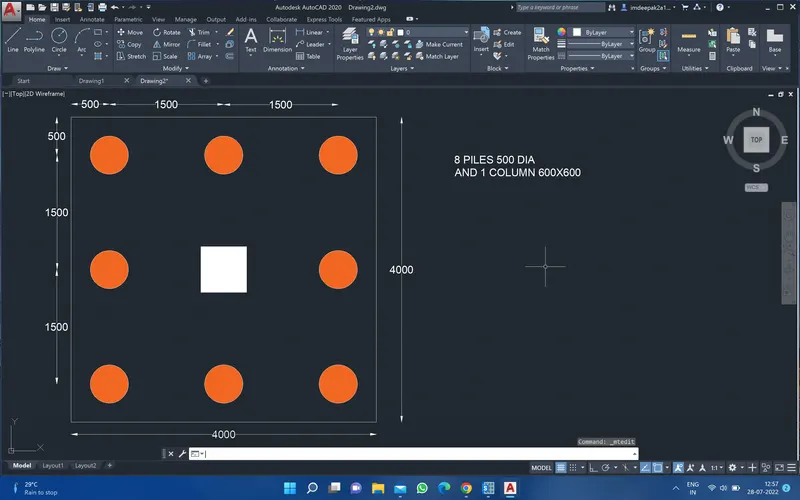
Consider 8 pile for symmetric placement of piles under pile cap
5. Take center distance between piles =(3 X pile dia)= 3x500=1500mm
6. Edge distance from the pile center= pile dia=500mm
so size of the pile cap = 4000mmx4000mm
*Tentative placement of pile
Now open your safe software set the grid and cap size and click ok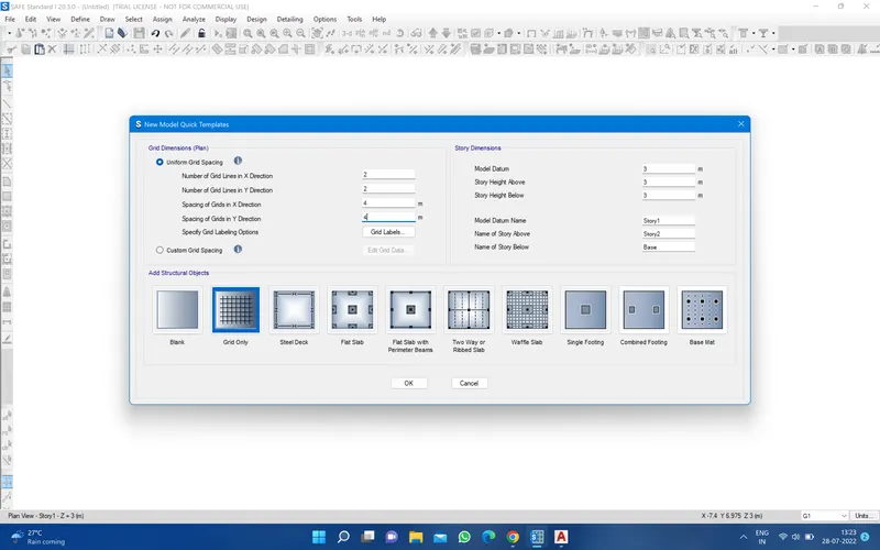
Then go to define material rebar and concrete fe 500 and M25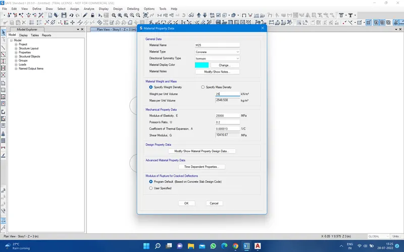
Then go to define section property and slab property and define pile cap , pile , and column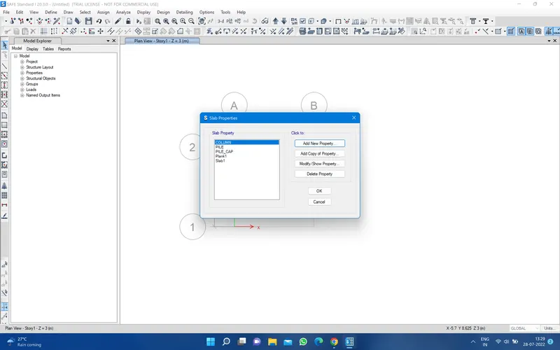
Then go to define and define spring property and point spring 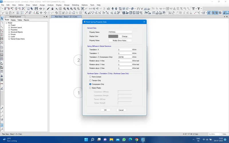
Then draw the pile cap 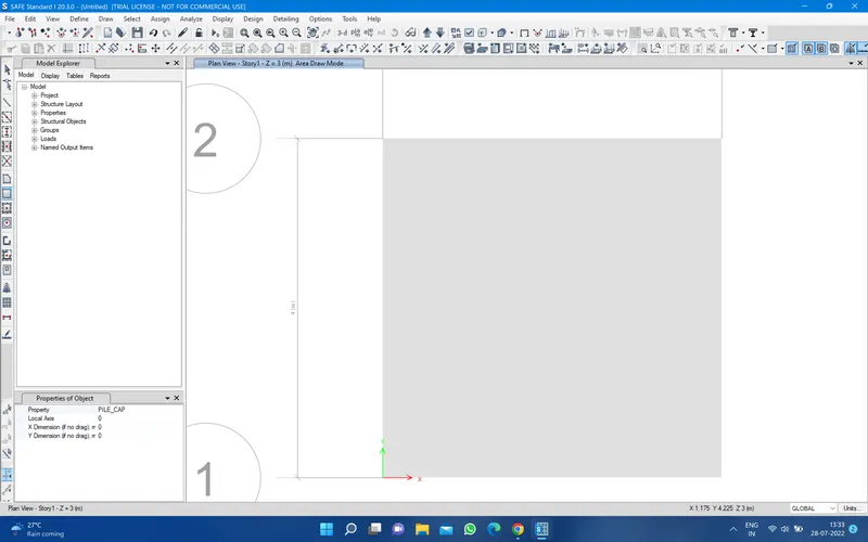
Befoure draw the pile cap draw the point for that just go to draw and select the draw point using coordinate draw the point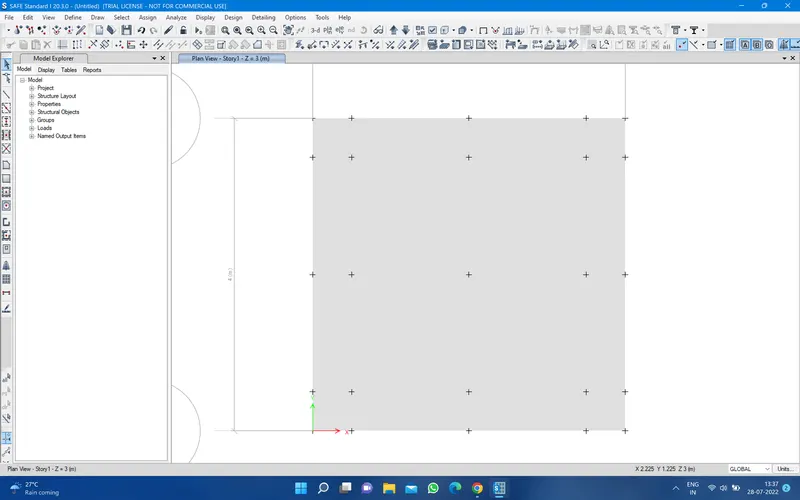
Then draw the piles and column and strip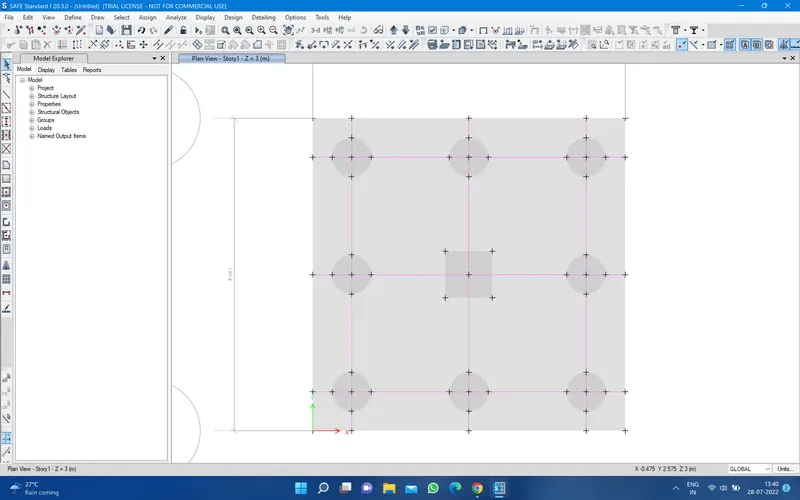
Then select the center point of the all piles and assign then go to joint then spring and select the load and apply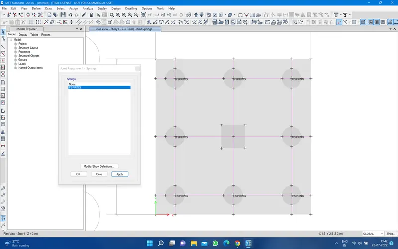
Then select the column point and go to assign and select the joint load and click on force and apply 1175 KN load in z direction 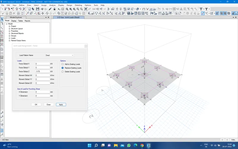
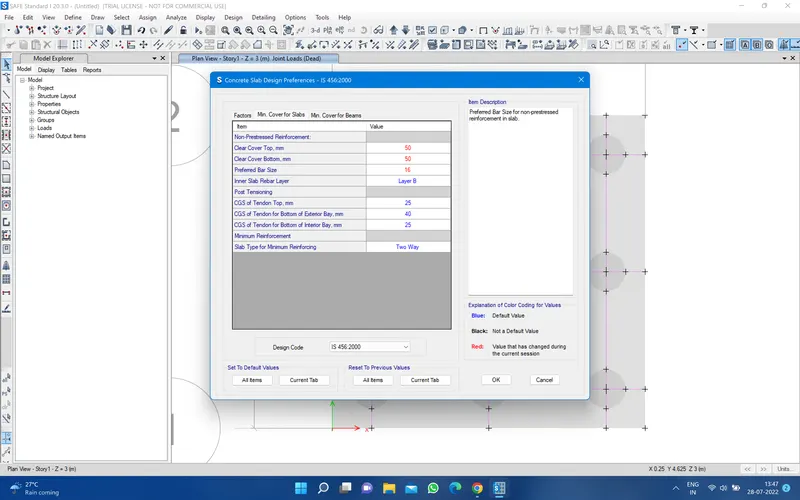
Now go to run analysis 
Frist go to check punching 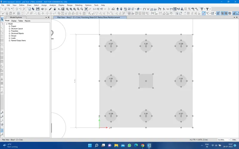
it is all right
secont go to check point reaction 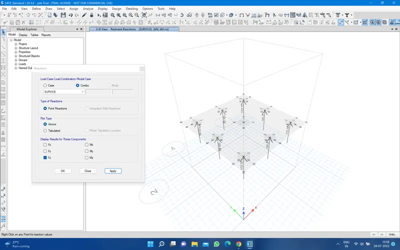
all almoust 200 kn it good
go to check deform shape 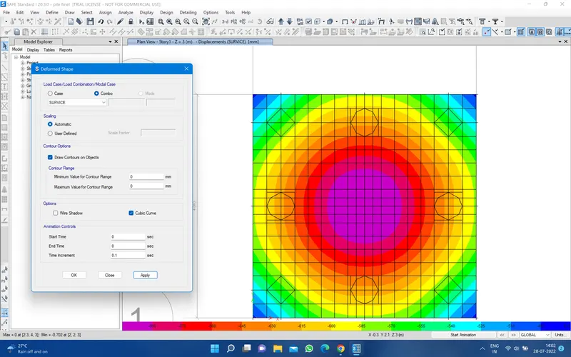
Fluctural reinforcement design for footing slab 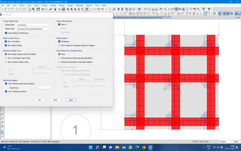
for the number of bars
No of bars with 100mm spacing=(length of the bar /100)+1
length of the bar =4000mm
(4000/100)+1=41 bars
No of the bar with 125 mm spacing=(4000/125)+1=33 bars