Foundation Design using SAFE
QUESTION 1
Objectives of the challenge
- To know the general design procedure of spread footing with SAFE software
- to know the general procedure of pile foundation with SAFE software
Data available
Column size = 400 mm x 400 mm
Factored load on column = 2000kN (1.5DL + 1.5 LL)
Safe bearing capacity (SBC) = 150 kN/m2
Grade of concrete = M25
Grade of steel = 500MPa
Data required for SAFE
Unfactored load = 2000/1.5 = 1333.33 kN
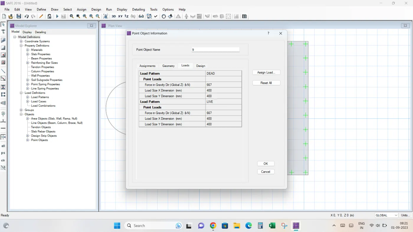
Dead load applied is equal to half of total load (Assume) = 1333.33/2 = 666.7kN
Live load applied is equal to half of total load (Assume) = 1333.33/2 = 666.7kN
Subgrade modulus of soil (footing rests on soil so soil properties needs to be considred)
= Safe Bearing Capacity x FOS (3)/ max allowable settelement
= 150 x 3/0.05(m) (permissible settelement = 50mm)
= 9000 kN/m3
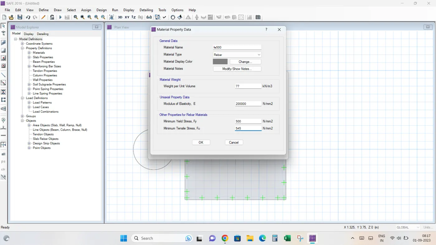
Yield strength of steel = 500 MPa
Ultimate tensile strength say 575 Mpa
Modulus of eleasticity of concrete = 5000SQRT (fck) = 25000 MPa
Modelling on SAFE software
New Model opened on Safe with Following definitions and design considerations. Unit system taken as metric SI
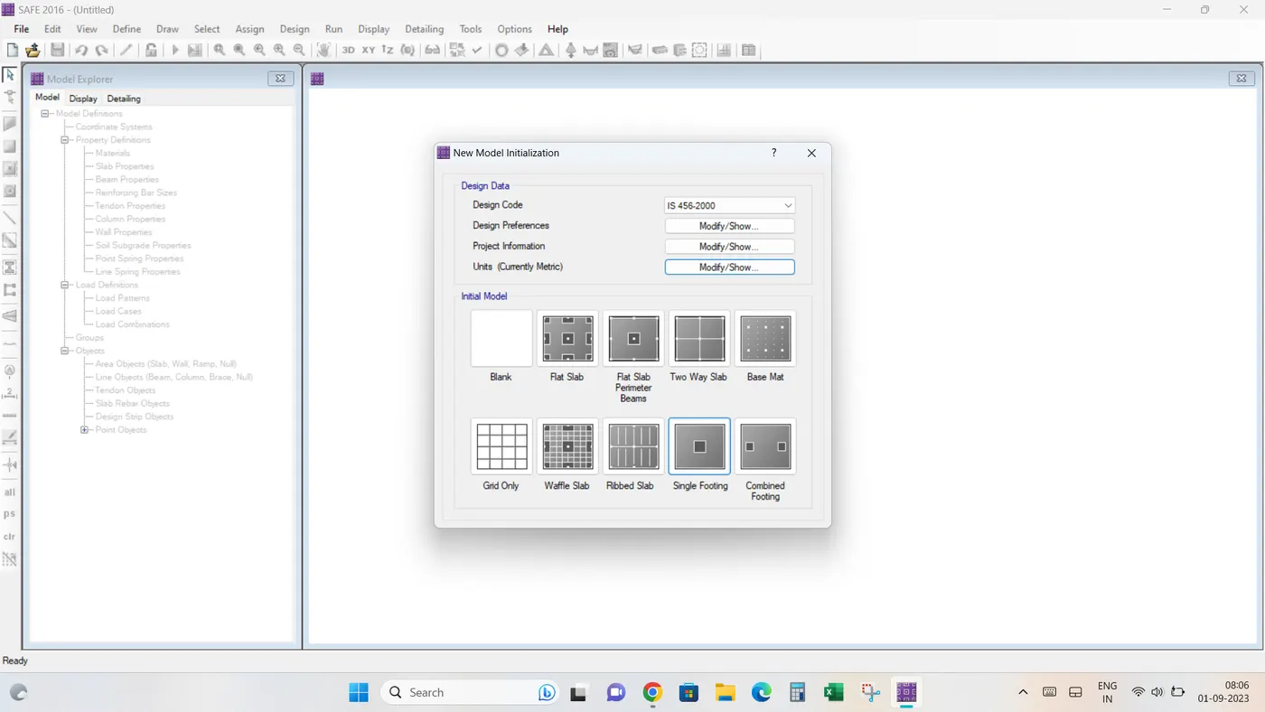
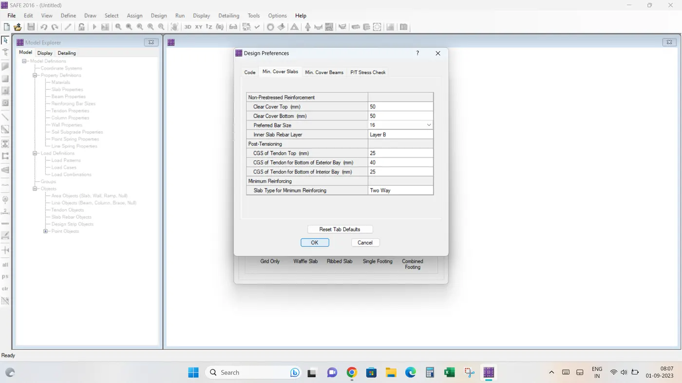
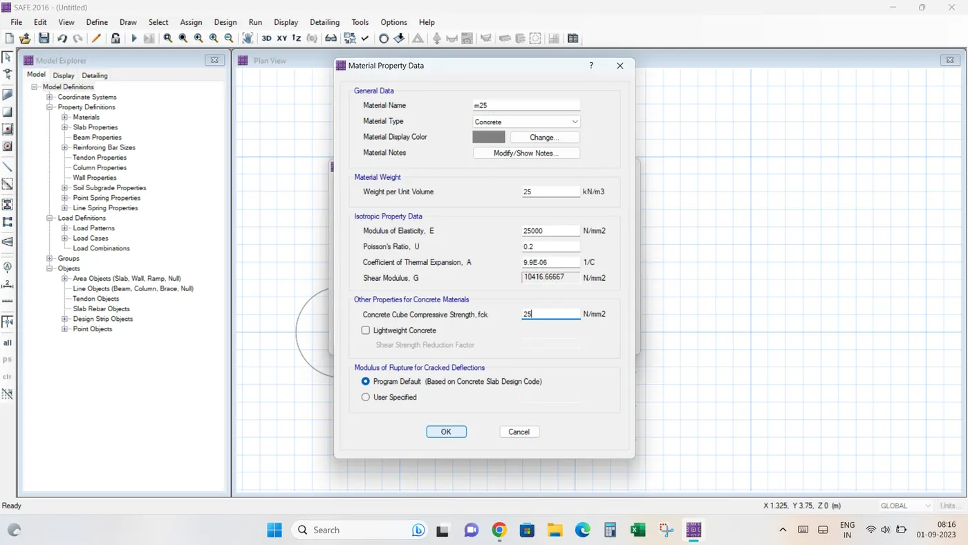
Default Isolated footing section template is selected and input vales such as Size of footing,Dead and Live loads (Unfactored), Footing thickness and Subgrade modulus of soil
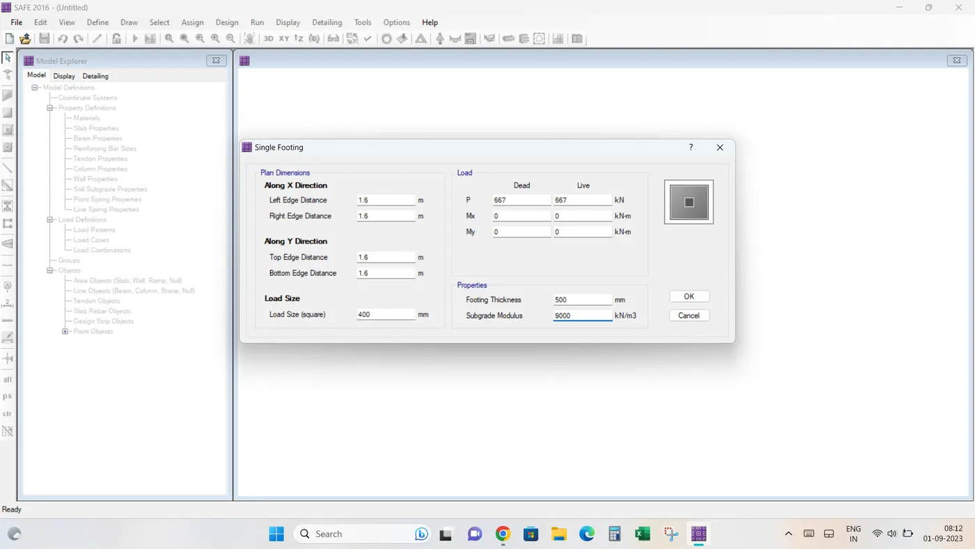
Defined materials propertis for M25 concrete and fe500 grade steel
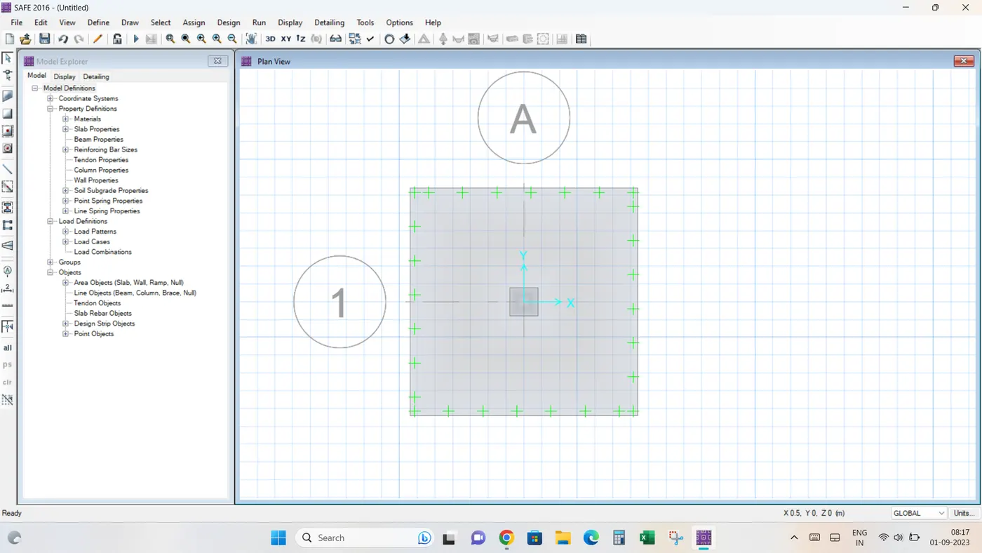
Geometric model of the fooing appeared
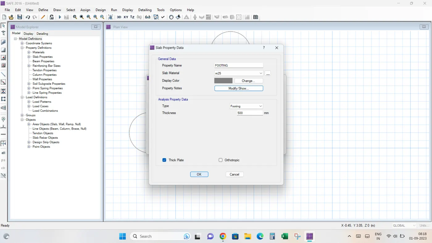
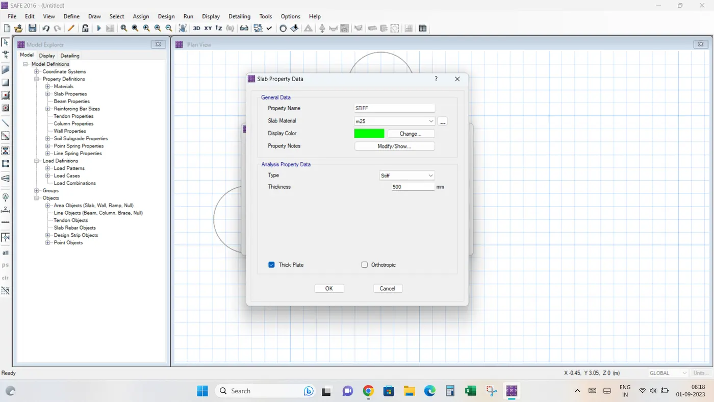
Defined Footing section as SLAB and column section as STIFF in slab section properties in "Define" section
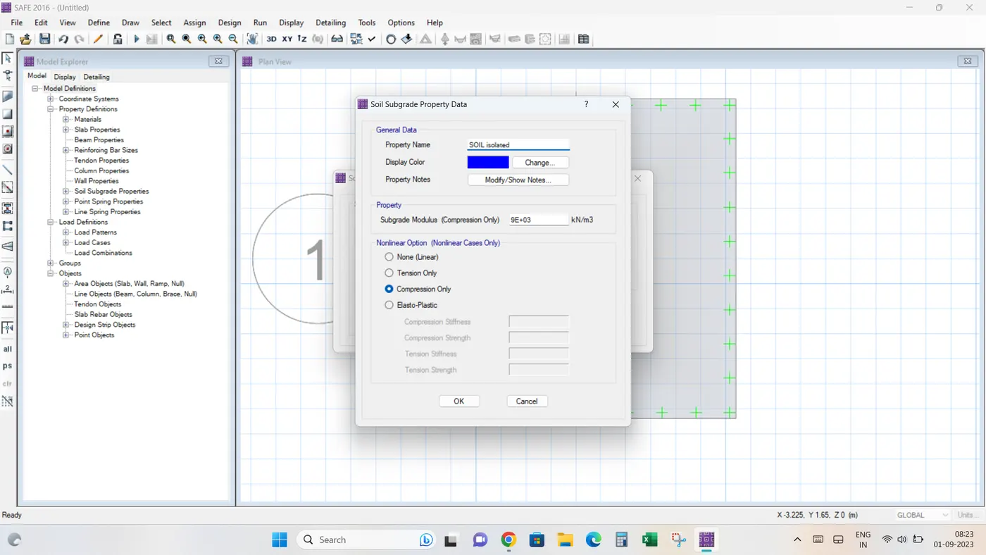
Soil Subgrade data defined with soil subgrade modulus
Assigned Load data in Assign section on the column grid intersection point with specified unfactored values
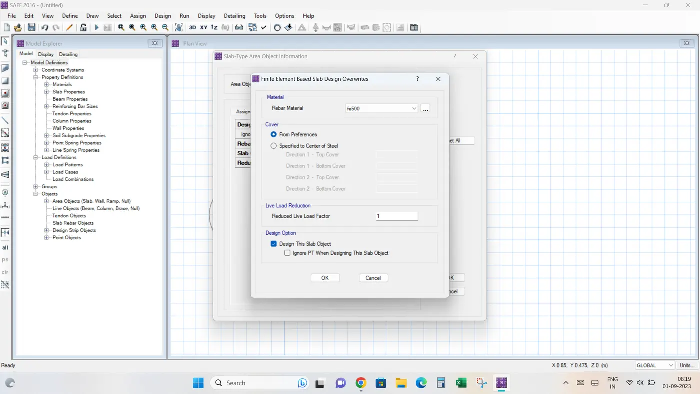
Cross checked both footing and stiff sections were assigned with rebar material Fe500 by right clicking on the same
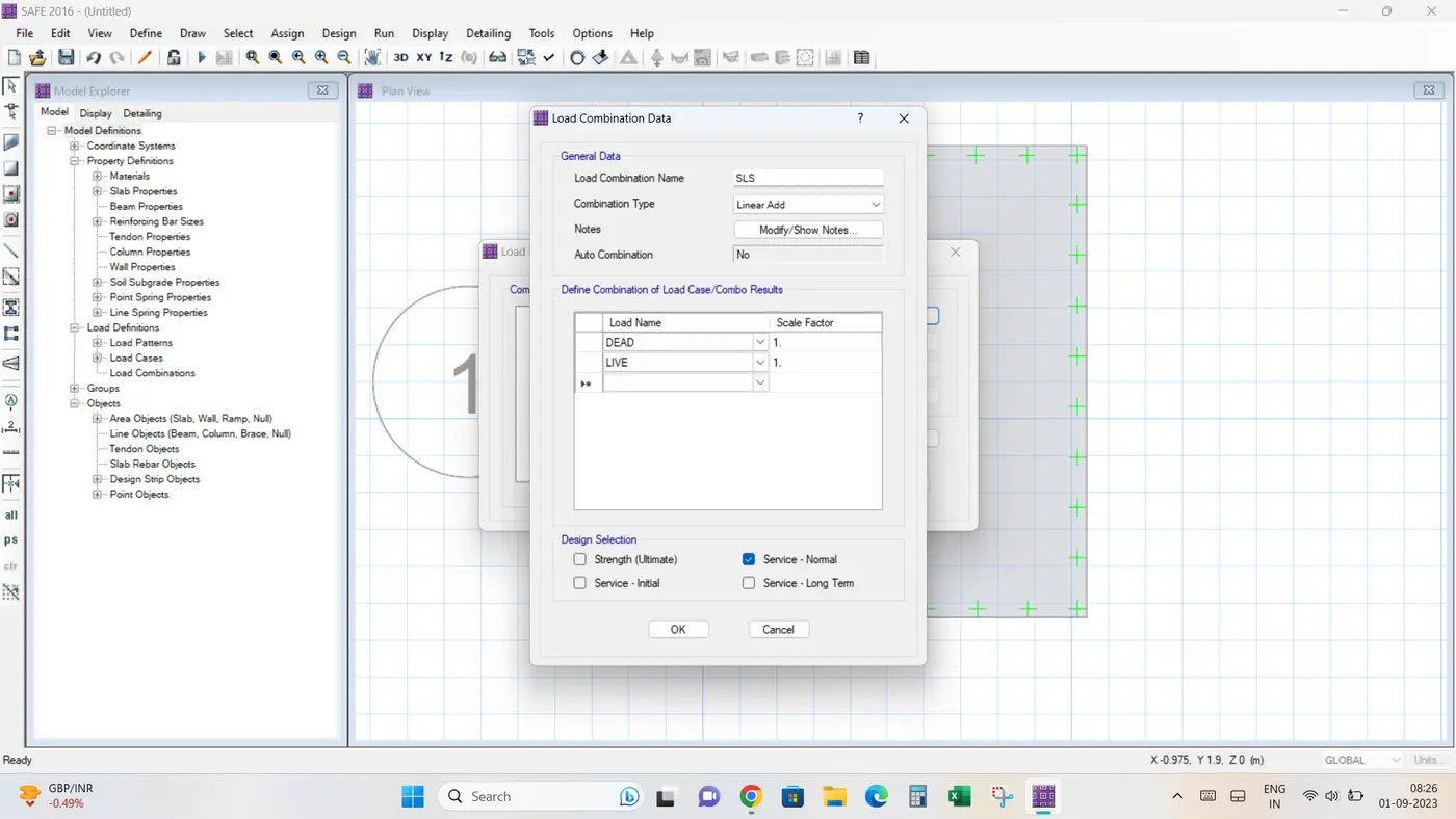
Defined Load patterns on Service and ultimate conditions and named SLS and ULS respectiveley. SLS Load combination were both LL and DL load factor as 1 and for ULS they are 1.5 each respectively
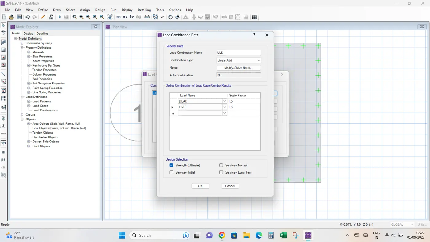
Cross check design preferences and design combod once again and run the analysis
After the completion of the analysis following things must be checked and verified
- Safe Bearing capacity under service load(Bearing pressure under service load)
- Settlement under service load (here should be less than 50mm)
- Punching shear check (should br less than 1 and preferably less than 0.9)
- Ultimate Bending moment
- Settlement under service load
Go to display > Show deformed shape > select SLS Load combo
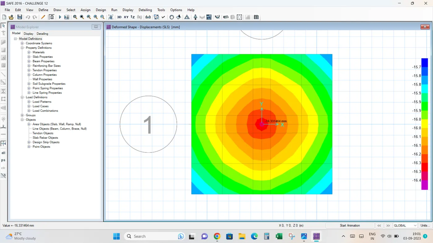
Maximum settlemet under service load is around 17mm which is way lesser than max permissible settlement of 50 mm or even 25 mm so safe in settlemet criteria
2. Bearing pressure check
Go to Display > Show reaction force > Select load combination SLS > select soil pressure
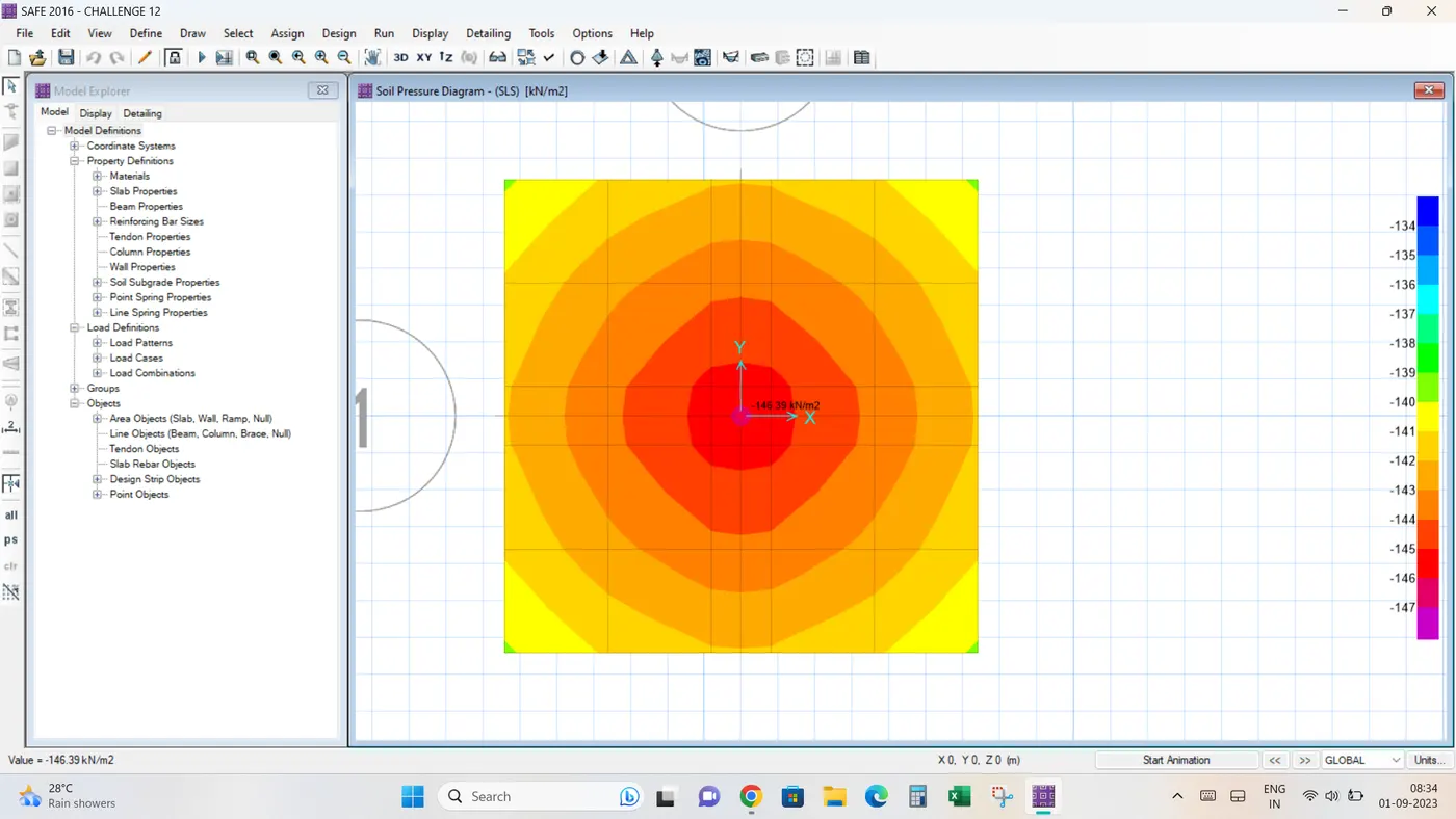
Maximum value obtained is around 147 kN/m2 which is lesser tha SBC (150 kN/m2) under service load combination Hence safe in bearing pressure
3. Check for punching shear
Go to display > show punching shear design
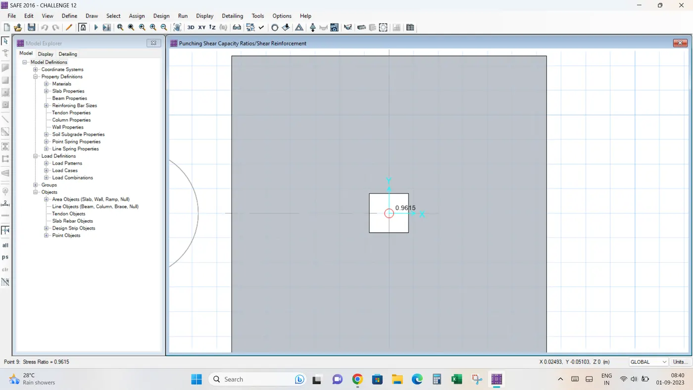
The value obtained is 0.9615 which is close to 1. Inorder to ensure saftey under various condition , it is good to increase the depth lower down this value. Hence indrease depth of footing to 550mm from 500mm
and run the analysis again
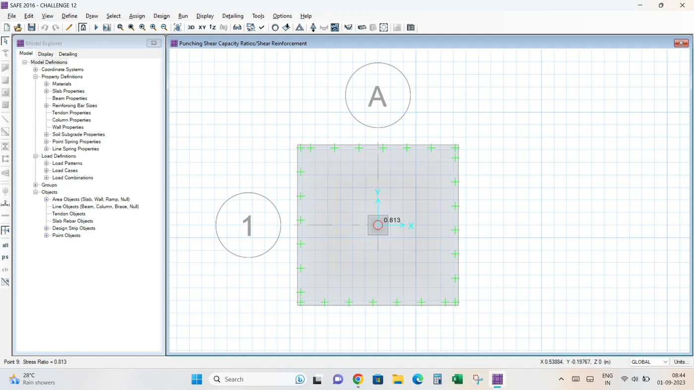
Now the ratio reduced to 0.813, which is pretty much satisfacory for punching shear safetey
4. Maximum Bending moment
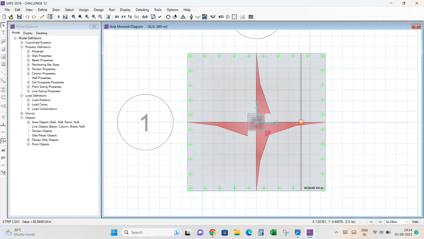
Maximum BM obtained is around 400 kNm at the face of column indicating the footing behaves like a balanced invarted cantilever
All the checks have been pased and Design can be done
DESIGN OF ISOLATED SHALLOW FOUNDATION
For that we need to draw design strips in X and Y direction in edit> draw design strips
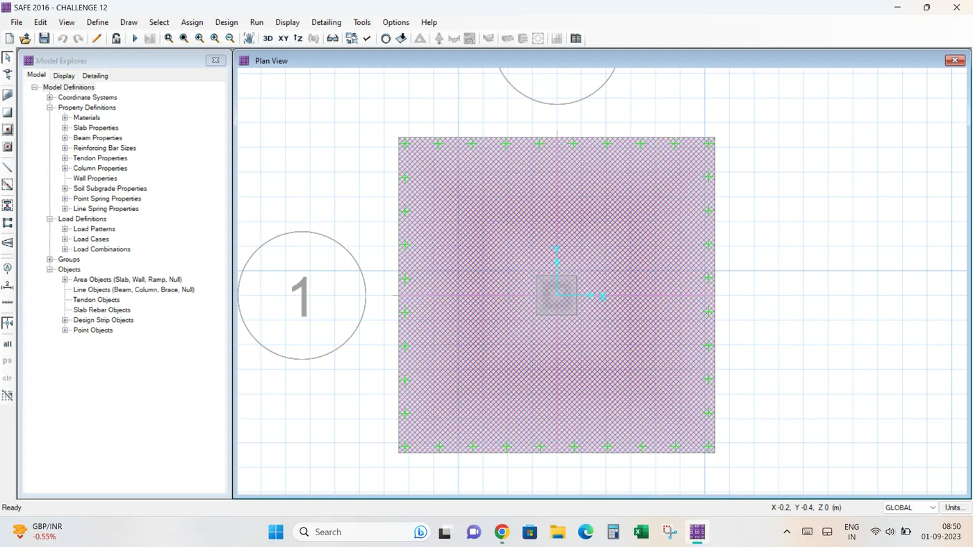
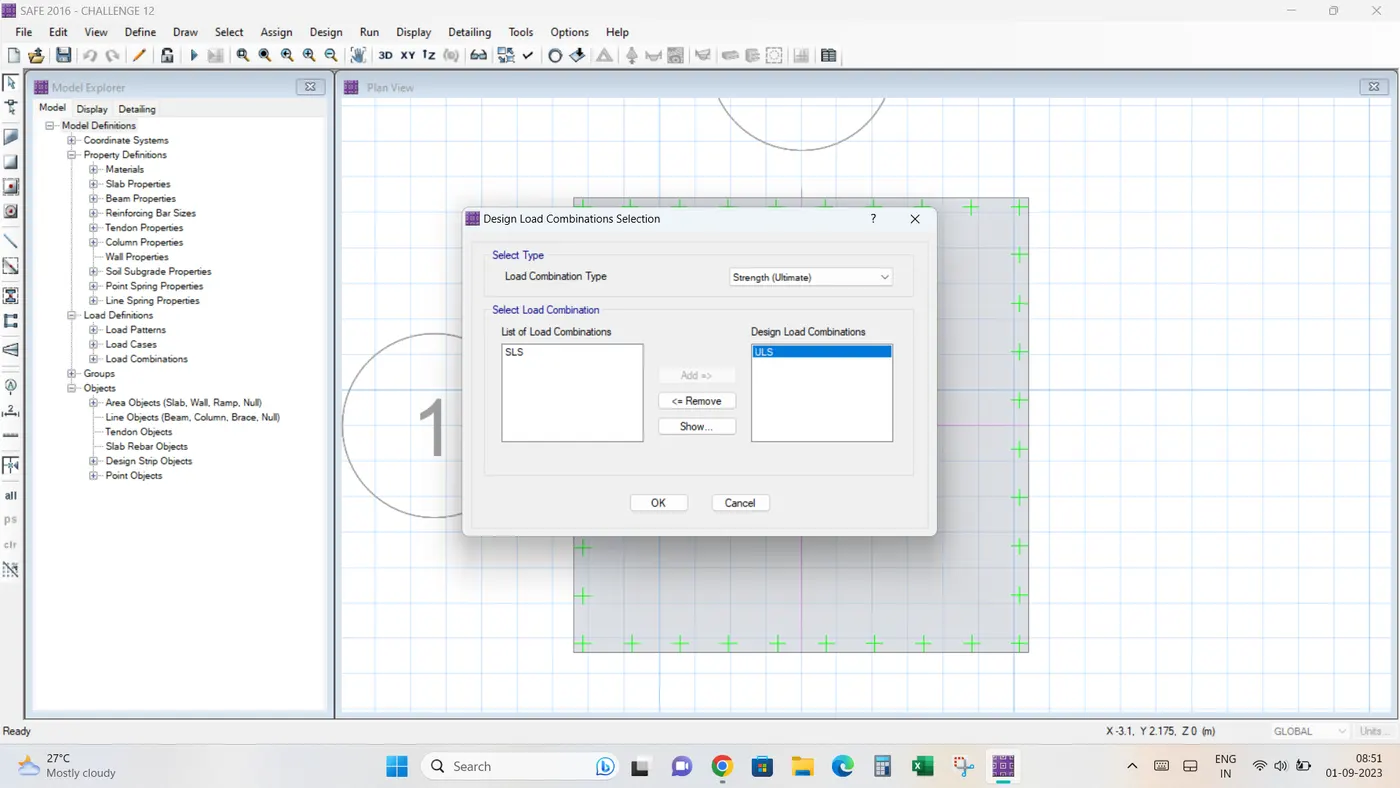
Steel design is done only with ultimate limit state load combinations with load factor for DL and LL as 1.5
Go to Display> show slab design , pick slab based design and select Layer A and Layer B
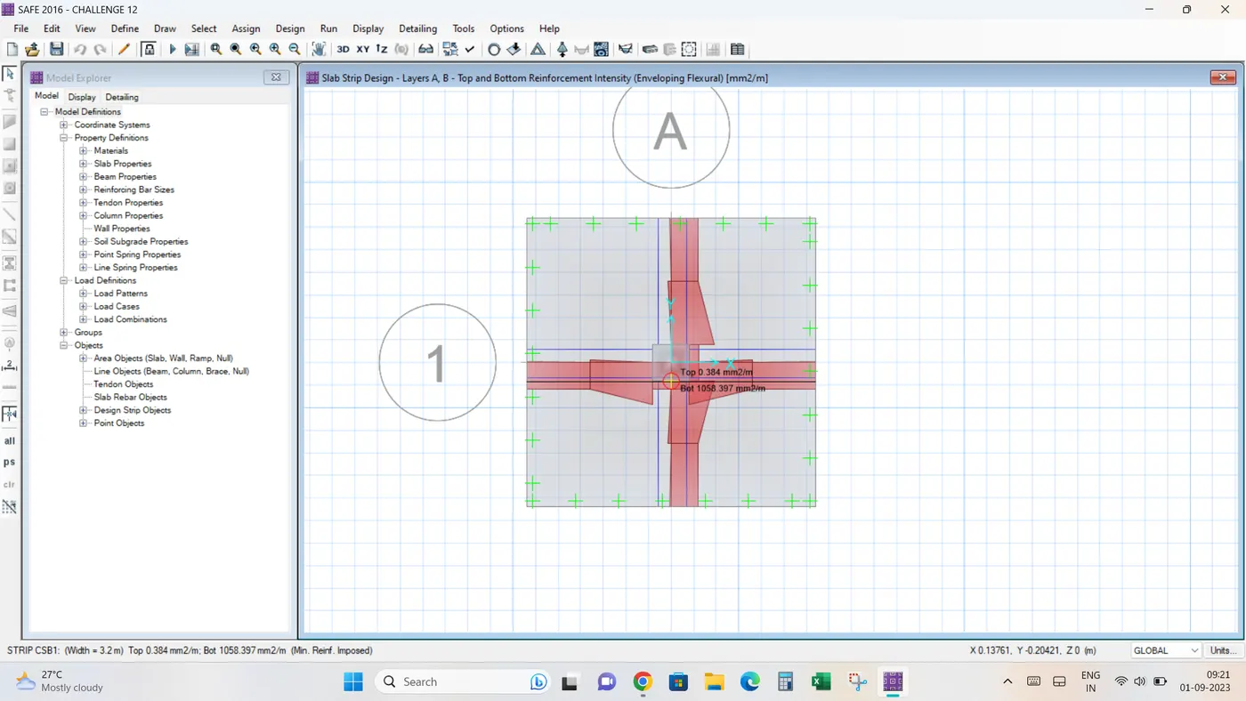
From the design values with the help of rebar intensity, it preferred to give 16 mm dia @ 150mm c/c spacing in both ways. Eventhough the rebar intensity is varying with depth it is advisable to go with equal spacing bothways for constructional easiness. On top eventhough hardly needed any reinforcement it id advisable to provide nominal reinforcement say 10mm @ 200mm is sufficient to carter temperature and crack width criteria.
QUESTION 2.
DESIGN OF PILE CAPS
Data provided
Column size = 600 mm x 600 mm
Service Load = 1175 kN (DL + LL)
Pile dia = 500 mm
Depth of pile = 16m
Pile capacity= 200 kN/pile
Data reqiuired for SAFE software
Unfactored load = 1175 kN
Dead load applied is equal to half of total load (Assume) = 1175/2 = 587.5kN
Live load applied is equal to half of total load (Assume) = 1175/2 = 587.5kN
Since we assume pile cap is resting on piles, we dont need to define any soil properties. But actually the will some interaction between soil and pile cap. Here in pile cap design we neglet it.
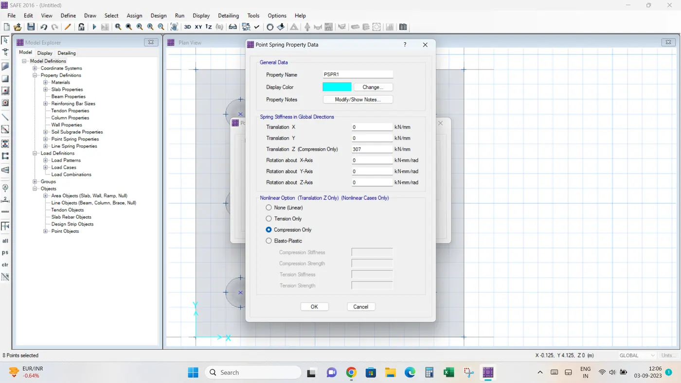
Piles are modelled as springs with specific stiffnes (stiffness of springs). So we need to assign stiffness for each pile
Stiffness (k) = AE/L = Area of pile x Modulus of elasticity of concrete /Length of pile
= 196500 mm2 x 25000N/mm2 / 16000 mm = 306.8kN/mm
Yield strength of steel = 500 MPa
Ultimate tensile strength say 575 Mpa
Modulus of eleasticity of concrete = 5000SQRT (fck) = 25000 MPa
Modelling on SAFE software
New Model opened on Safe with Following definitions and design considerations. Unit system taken as metric SI
Model initilisation and grid definitions are given below
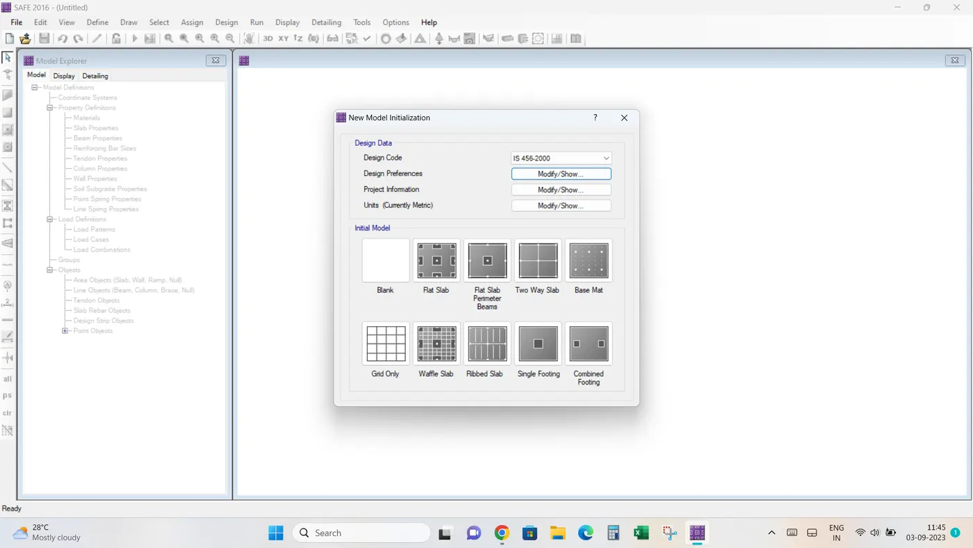
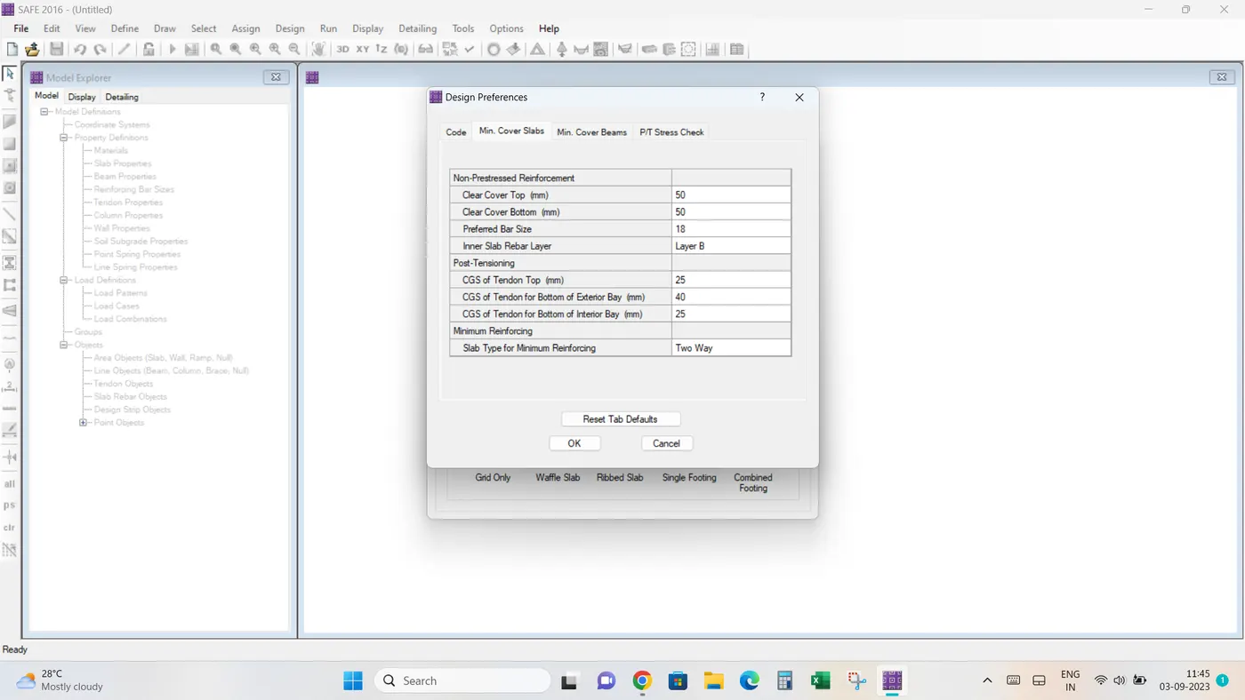
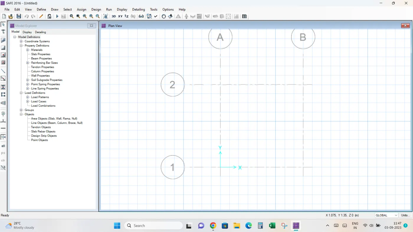
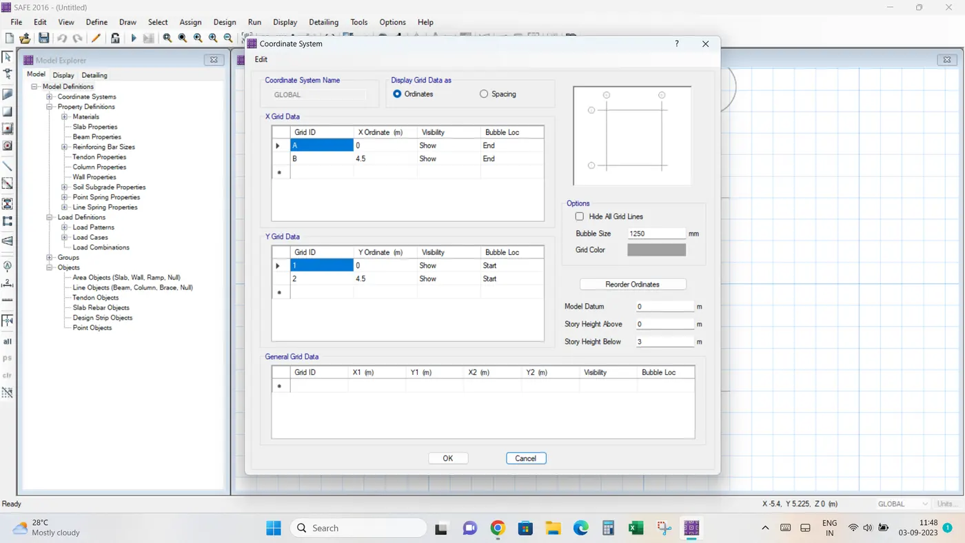
Defined all the materials M25 concret and Fe500 steel
In Slab property data in Define section, 3 Sections have defined namely COLUMNS, PILE CAP, PILE 500
Columns and piles defined as "stiff" and pile cap has "mat"
All sections assumed as same thickness of 500mm initially
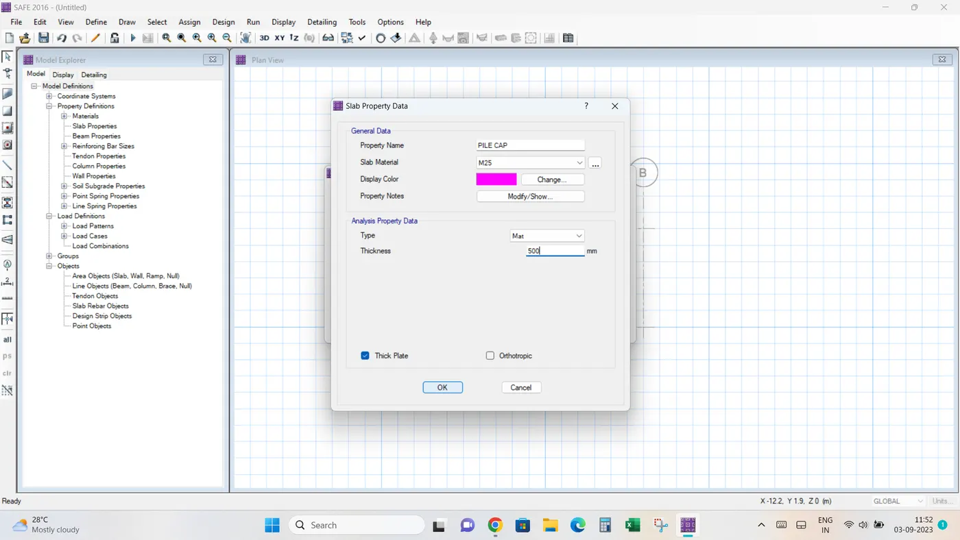
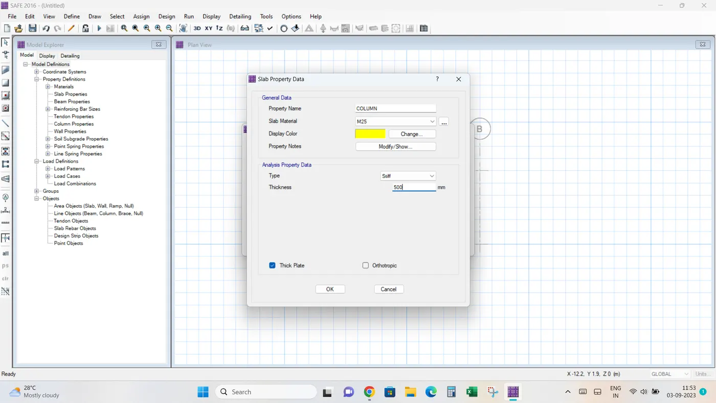
Now draw the pile cap in specified grid using draw slab tool
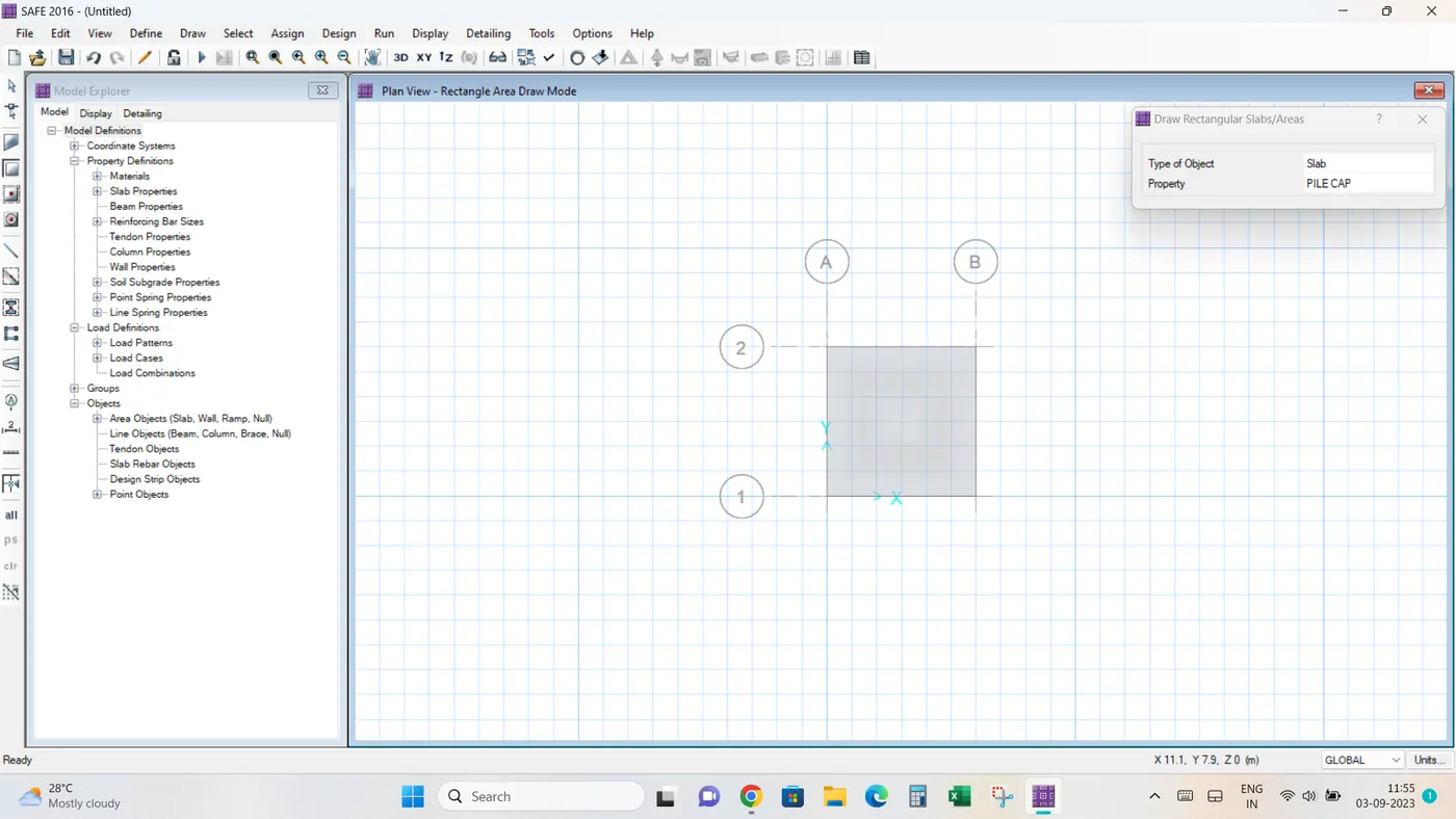
Now for drawing piles and column we need to draw points of centers of piles and columns as per drawing. Here c/c distance b/w piles is taken as 3 times dia of piles (3x500=1500mm) and edge distance as one time the dia of pile (1x500=500mm). which constitutes the total width of pile cap is 4500mm x 4500mm
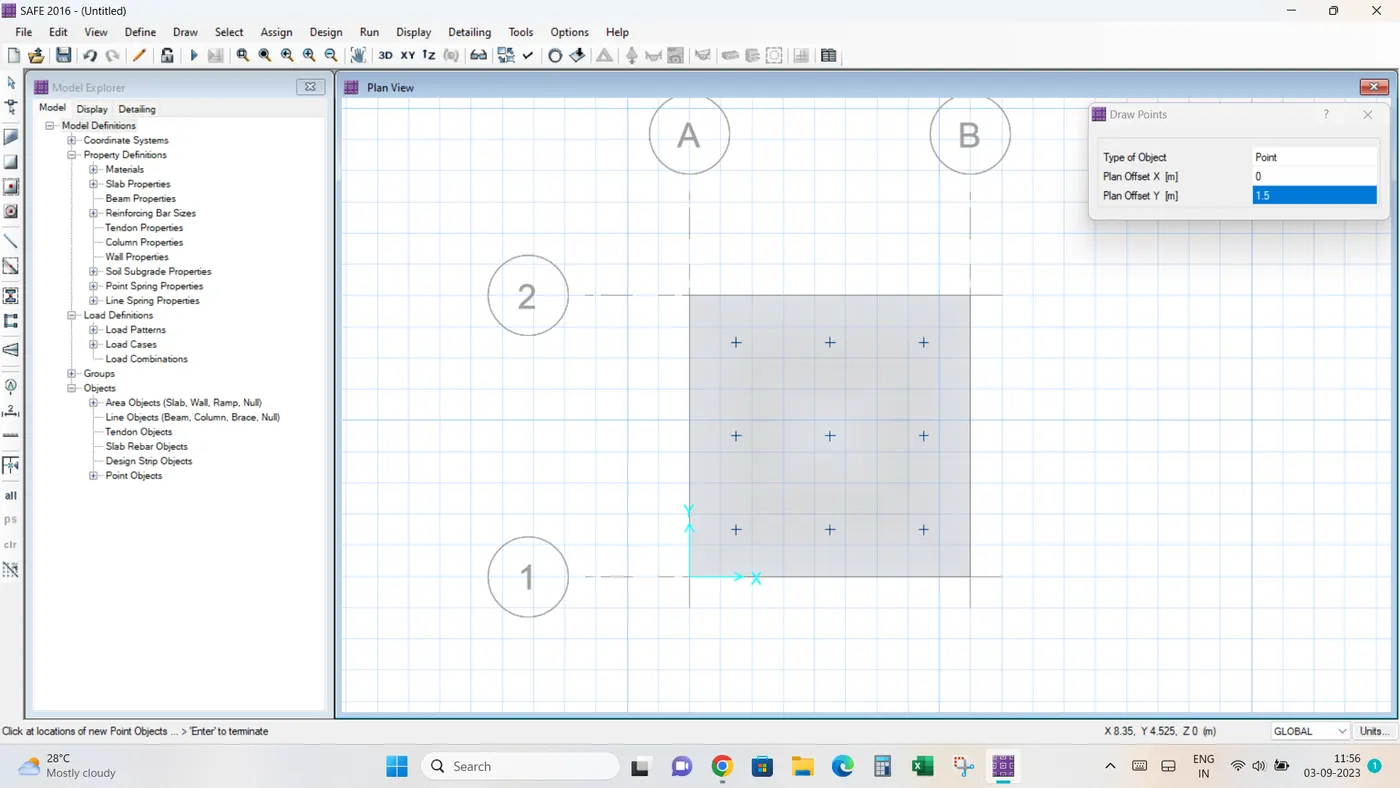
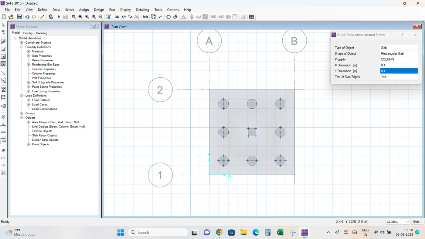
Using the tool draw area around point we can draw piles (circular with dia 500mm and column as rectangular with sides 600mm ) as shown below
To assign spring propertis for piles , select all pile centre points and go to Assign > support data > Point Springs . provide the value of Spring stiffness calculated earlier in the Z direction with non linera option compression only
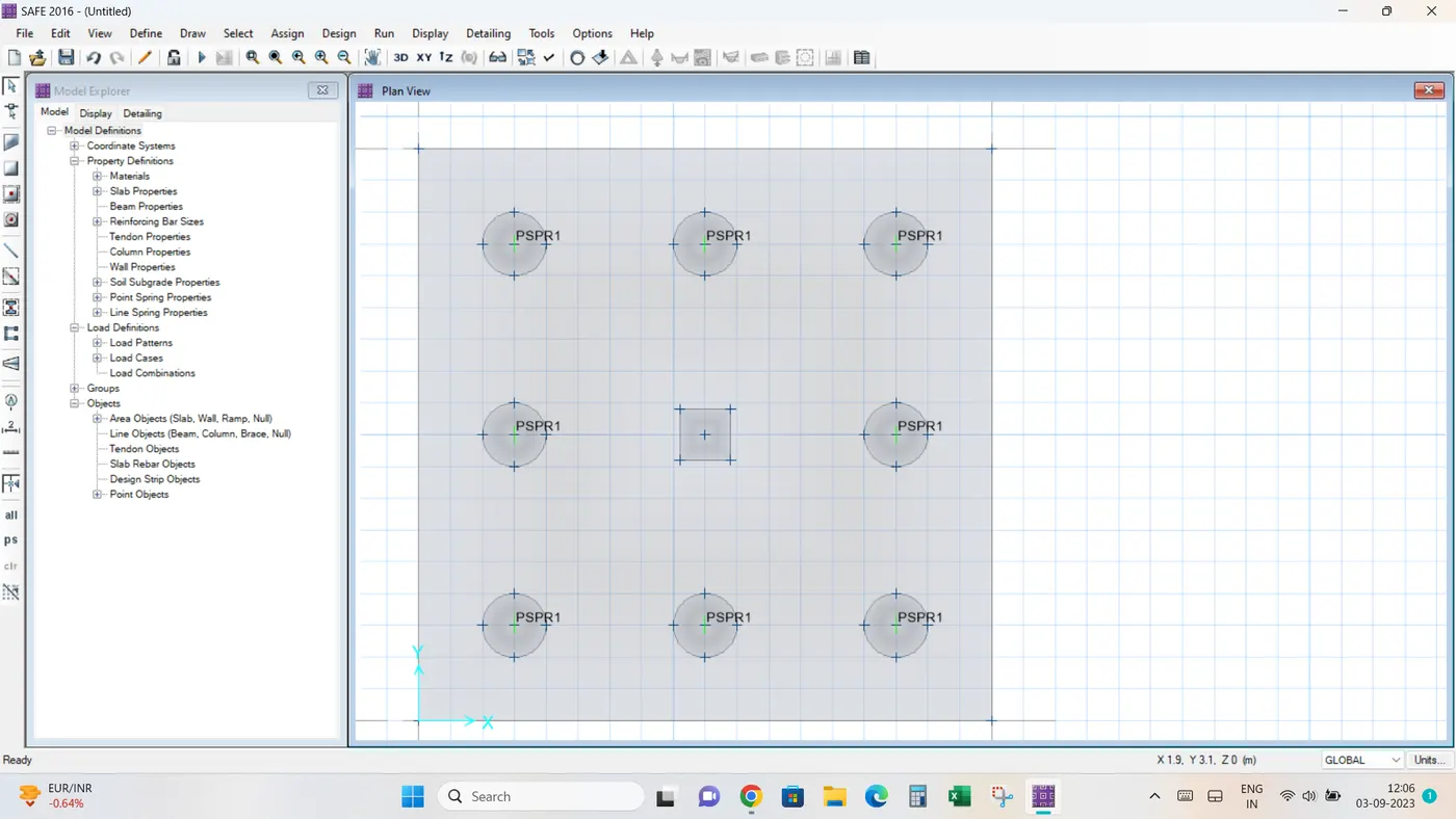
To assign loads to column pick the centre point of column and go to assign> Load data > point loads > give DL and LL as calculated earlier
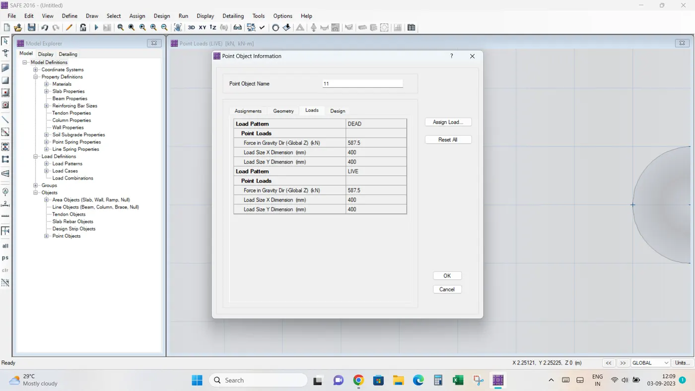
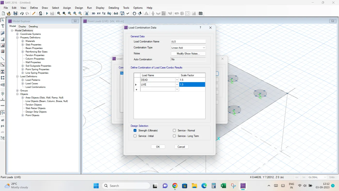
Give service load combination SLS with Load factor 1 ( for bearing pressure and settlement) and Ultimate load combination ULS with load factor (for steel calculation) 1.5.
Check once again the design preferences and rebar assignment for each slab property definitions and then it is ready to run the analysis
After the completion of the analysis following things must be checked and verified
- Reactions of each pile under service load(should be less than pile capacity)
- Settlement under service load (here should be less than 50mm)
- Punching shear check (should br less than 1 and preferably less than 0.9)
- Ultimate Bending moment
1. Check for Reactions of each pile under service load
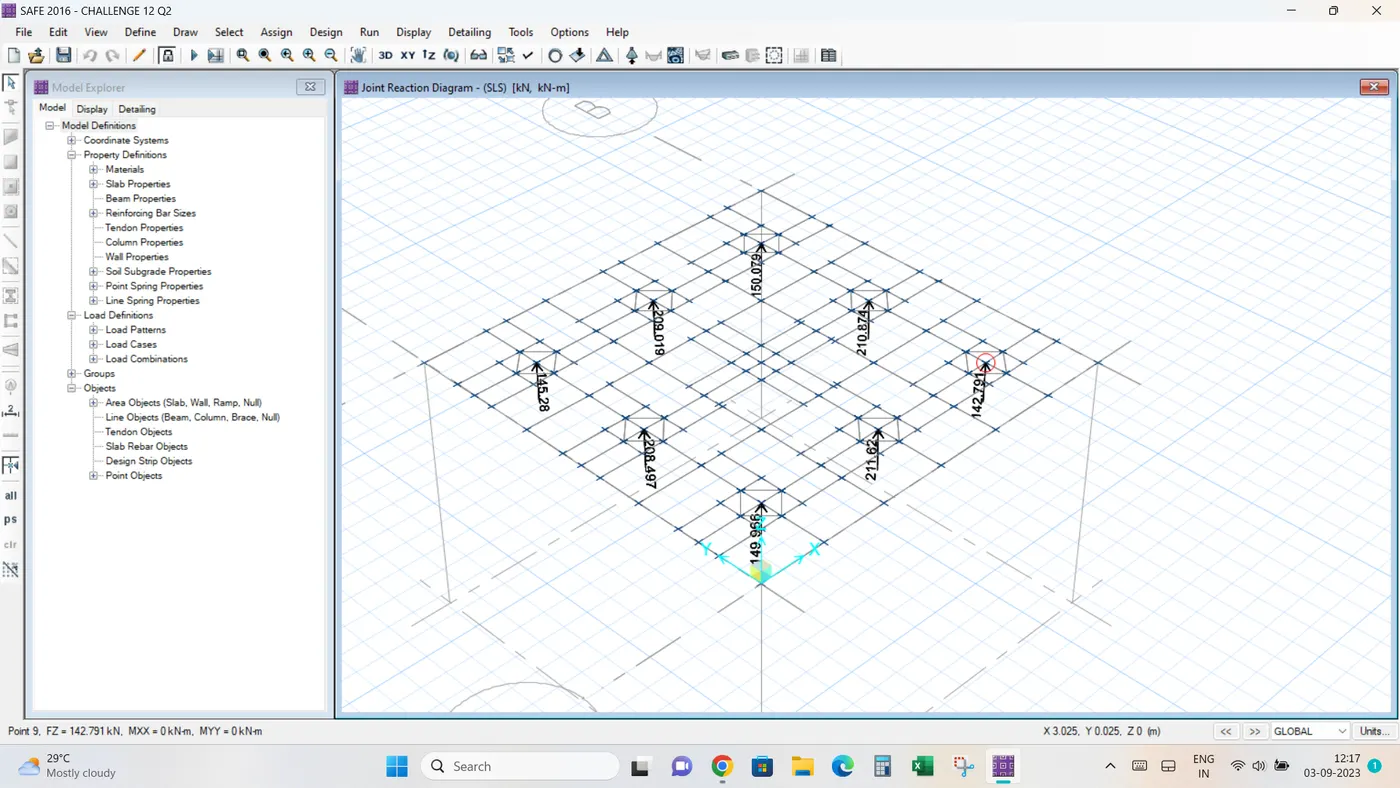
Pile load capacity of each pile is 200 kN(by assuming loads are shared equally by all the piles). here Piles near to column shows slightly higher values than the pile capacity. which is almost ok. However we can reduce the reaction by increasing the dimensions of pile cap. at the moment it is ok.
2. Settlement under service load
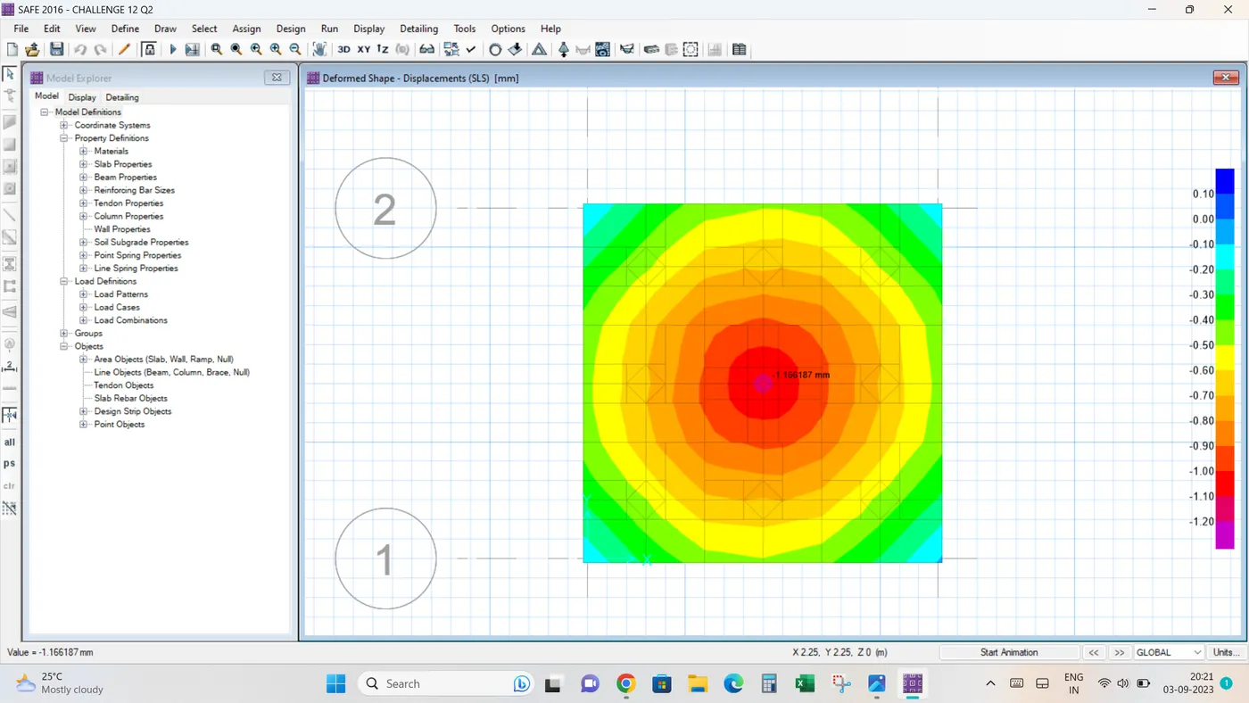
Maximum downward Displacement obtained is around 1.2mm which is very less compared to allowable max dispacement . Hence ok.
3 . Punching shear check (should br less than 1 and preferably less than 0.9)
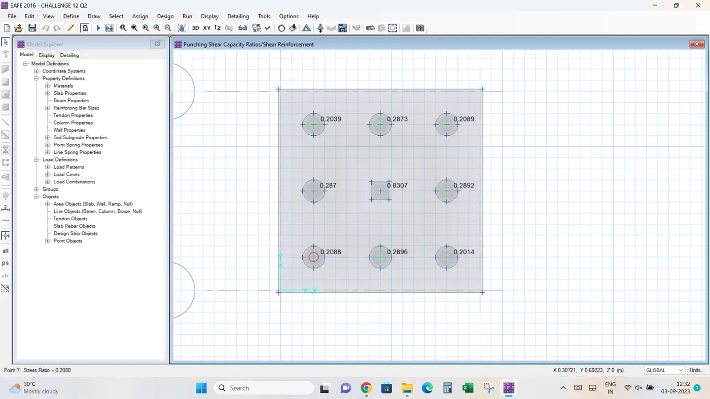
All values is well below 0.9 hence safe in punching shear
3.Ultimate Bending moment
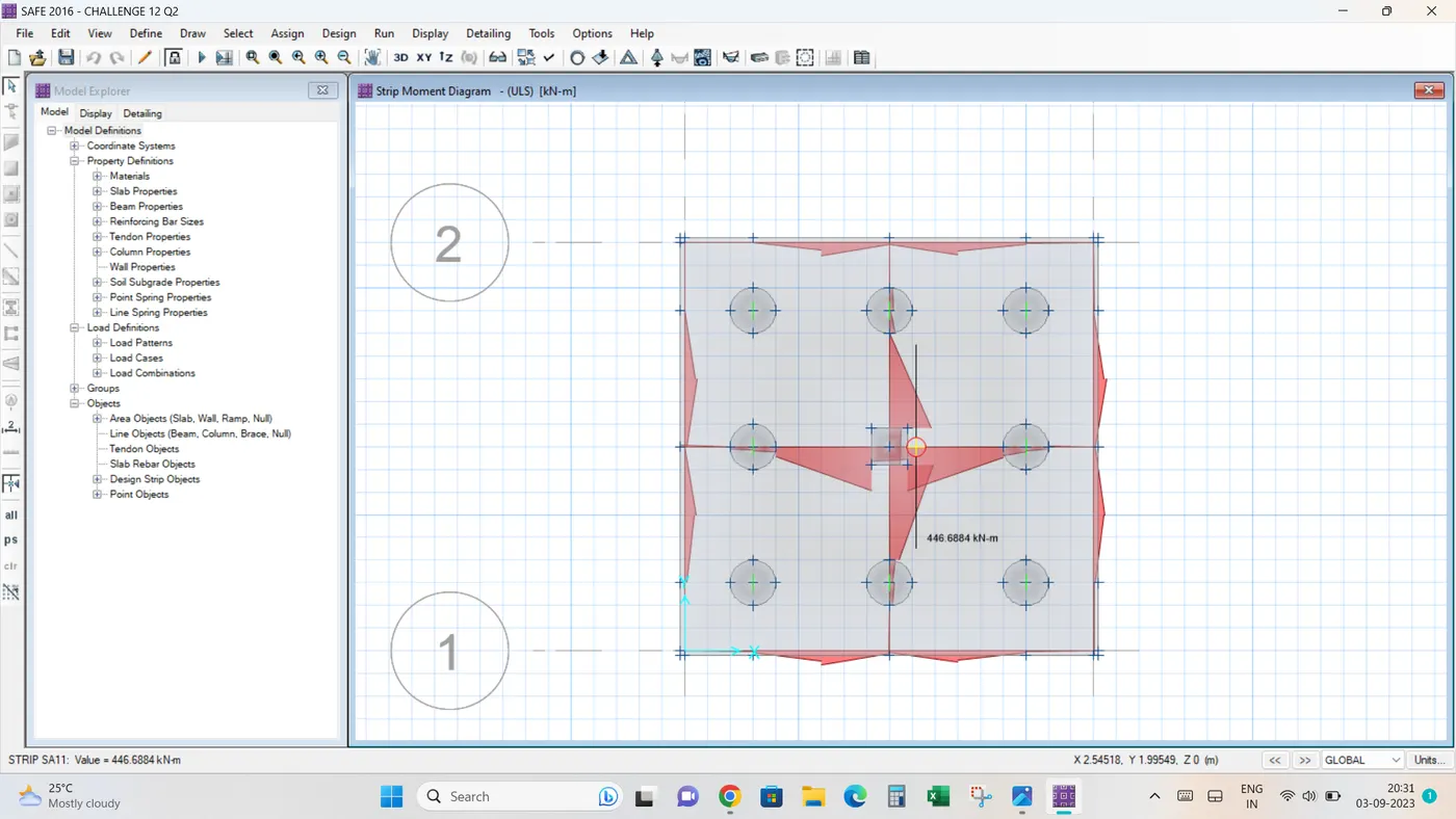
All the checks are passed now we can go for the Design of pile cap
For the design purpose need to draw design strips both in X and Y directions
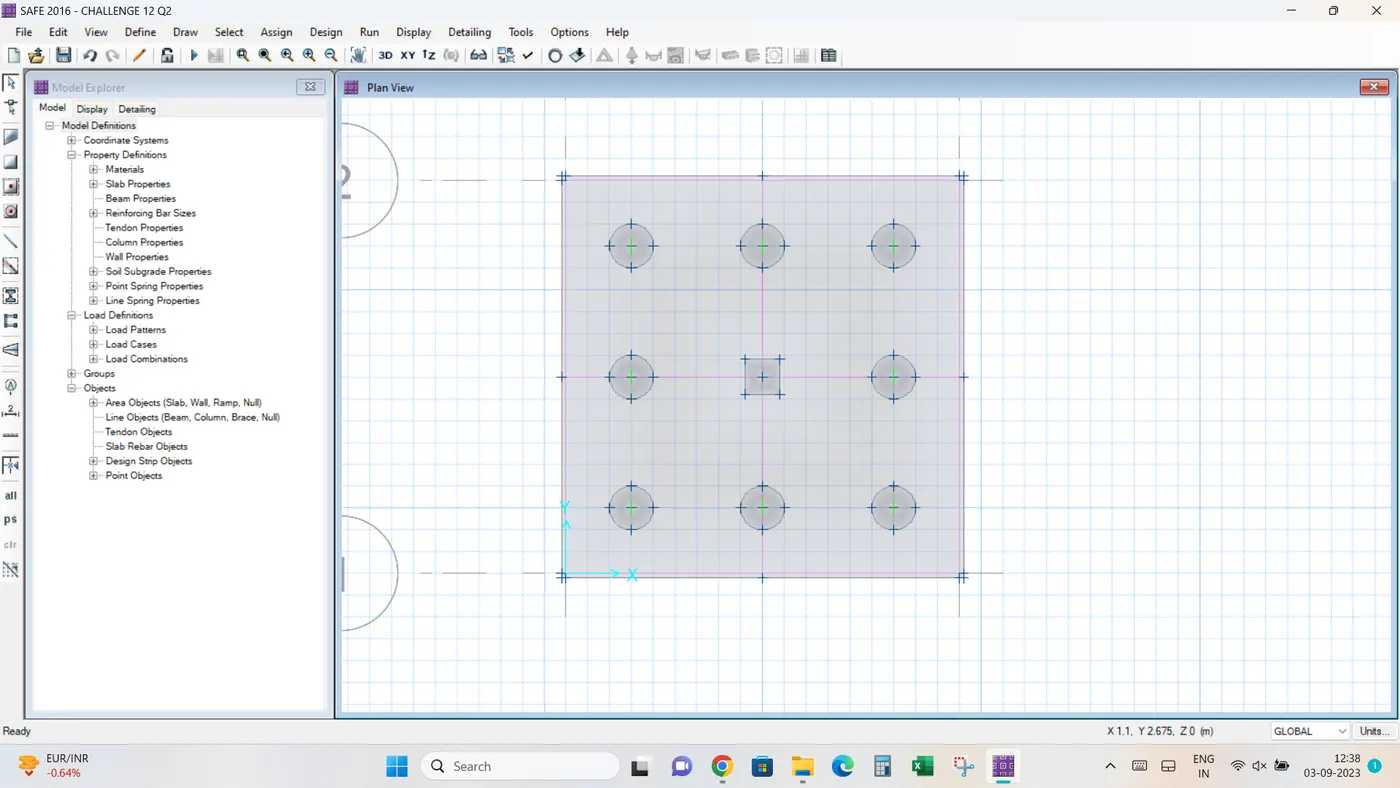
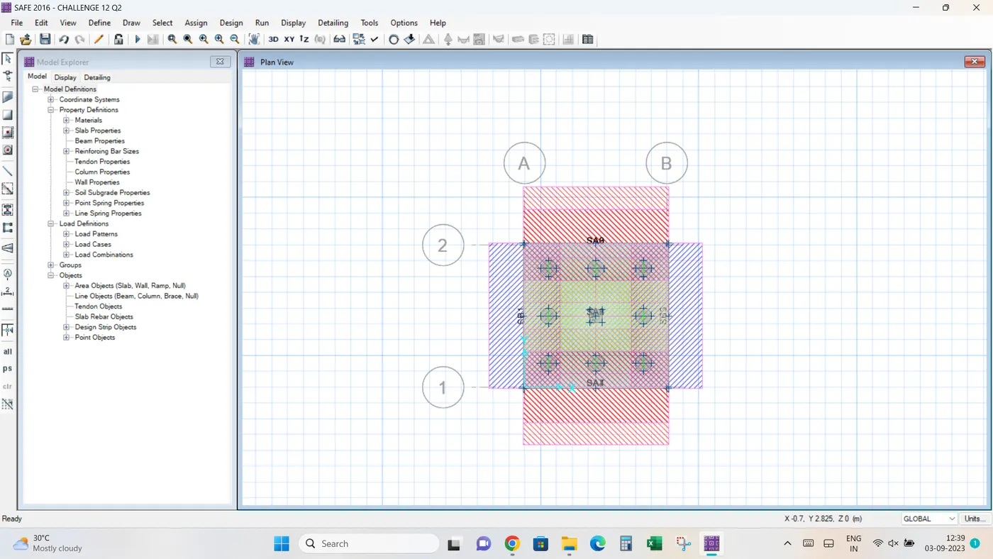
Go to Display> show slab design> strip based design> both layer A and B
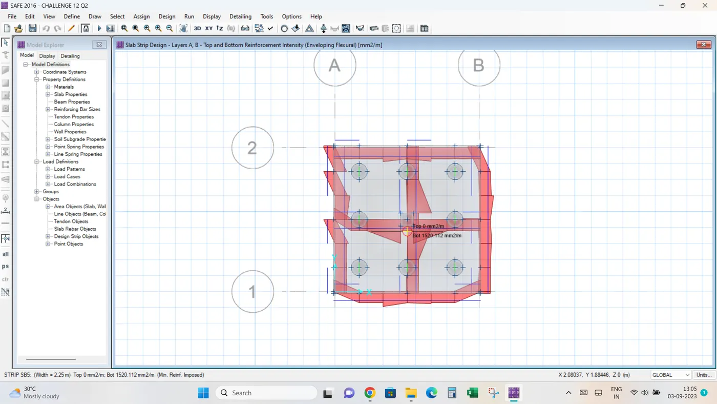
Max area of steel required is at face of the column in bottom face around a value near 1600mm2/m. so provide 16 mm dia bars @125 mm c/c both ways at bottom face throughout.
Also at edge there is a need of top reinforcement around 600 mm2/m . so provide 12 mm dia bar at 150mm c/c as top reinforcement.