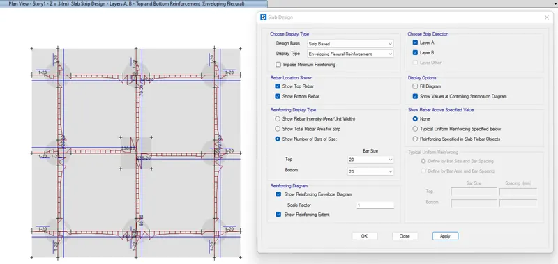
Foundation Design using SAFE
1.Model the isolated footing provided in week 11 challenge on SAFE. Analyze and design it to verify the size, depth and steel provided as per calculations.
AIM:- To model the isolated footing by using SAFE and to analyze and to design it to verify the size, depth and calculation of steel provided
INTRODUCTION:- All the steps are going to be mentioned along with step by step procedure.
PROCEDURE:-
- Open SAFE software
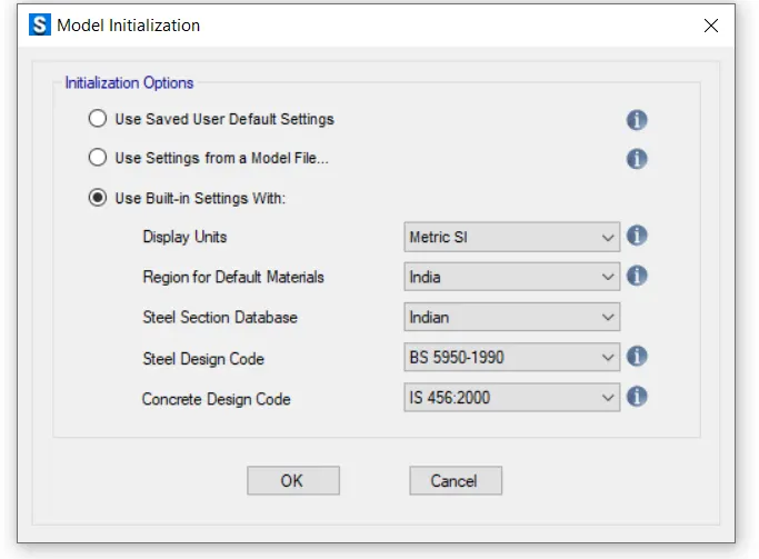
- Create a new model
- Edit the settings
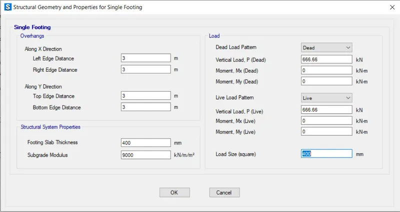
- Edit the structural geometries and properties as per the previous problem which is given below:-
Size of column = 400 mm * 400 mm
Unfactored gravity load (DL+LL) = 2000 KN
Safe bearing capacity of soil = 150 KN/m^2
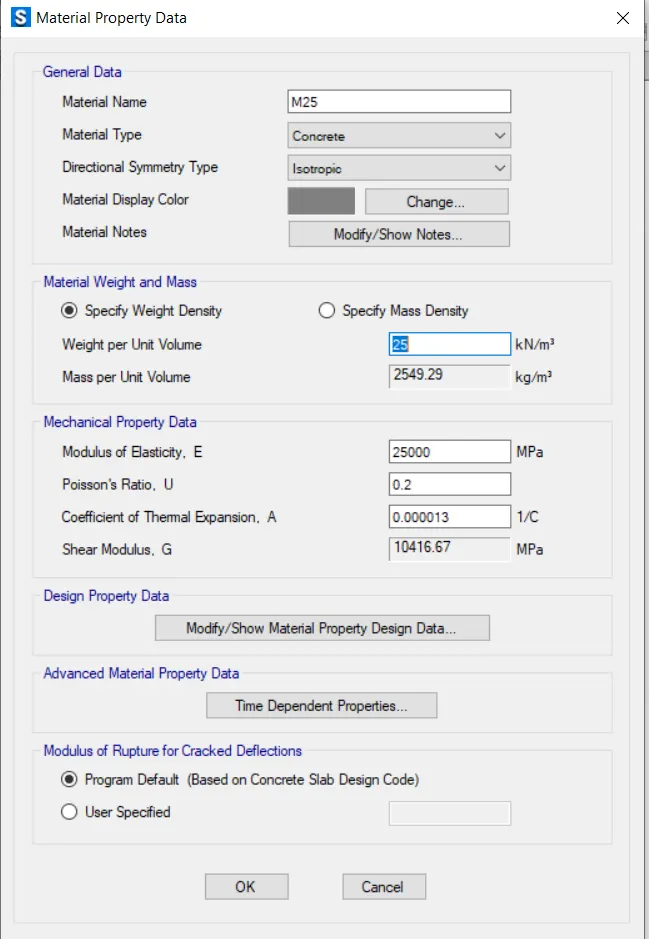
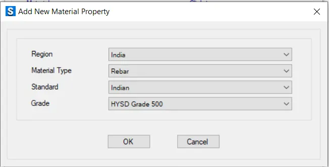
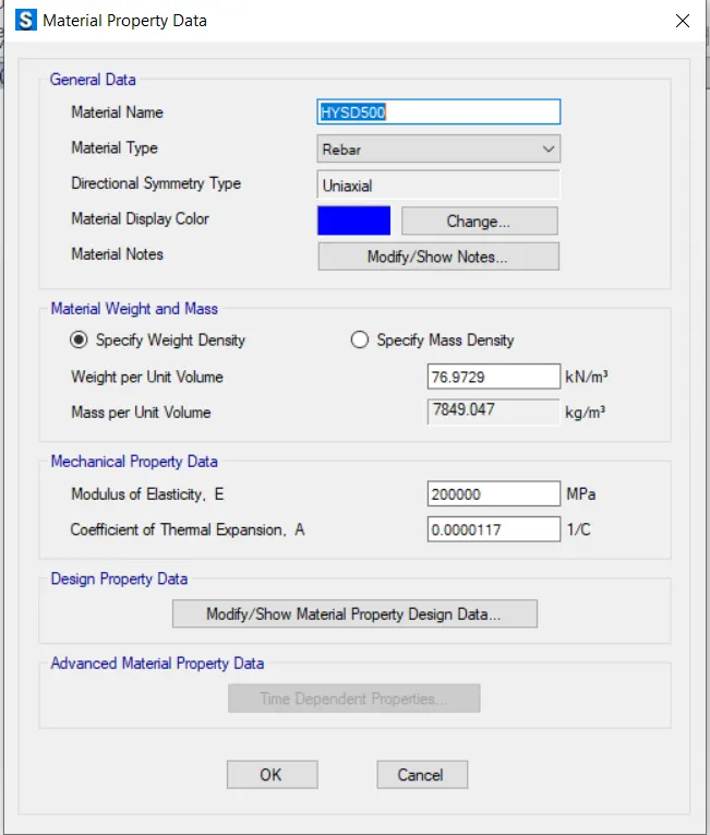
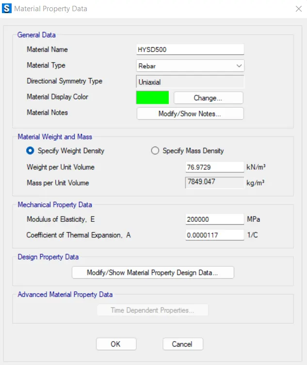
Assume M25 grade concrete and Fe 500 HYSD bars
Settlement = 50 mm
Take FOS = 3
Sub- grade modulus = FOS* Safe bearing capacity/settlement = 150*3/0.05 = 9000 KN/m^3
Unfactored gravity load = 2000/1.5 = 1333.33 KN
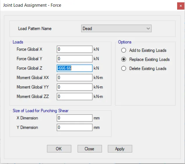
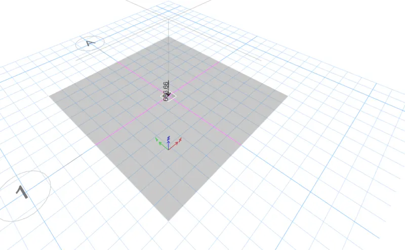
Dead load = 1333.33/2 = 666.6 KN
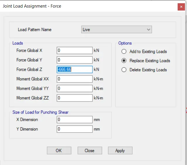
Live load = 1333.33/2 = 666.6 KN
Yield strength of steel , fy = 500 N/mm^2
Ultimate strength of steel, fu = 575 N/mm^2
Area of footing = 1333.33/150 = 8.88 m^2
Size of footing = L = B = √(8.88) = 3 m
Adopt 4 m * 4 m for square footing
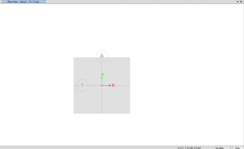
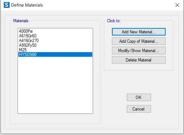
- Define materials
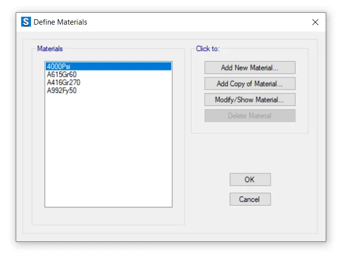
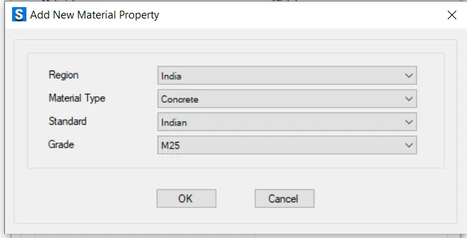
- Add new material property for M25 concrete
- Add new material property for Fe 500 HYSD bar
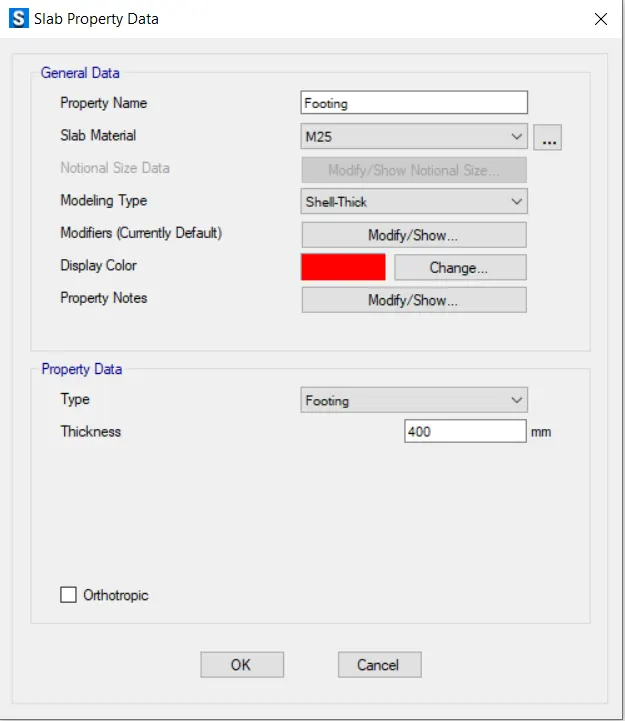
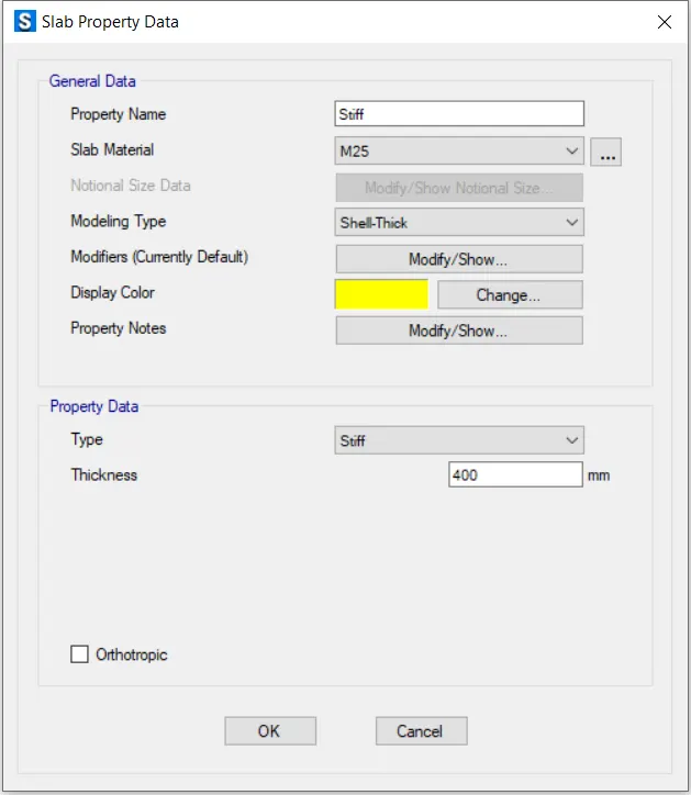
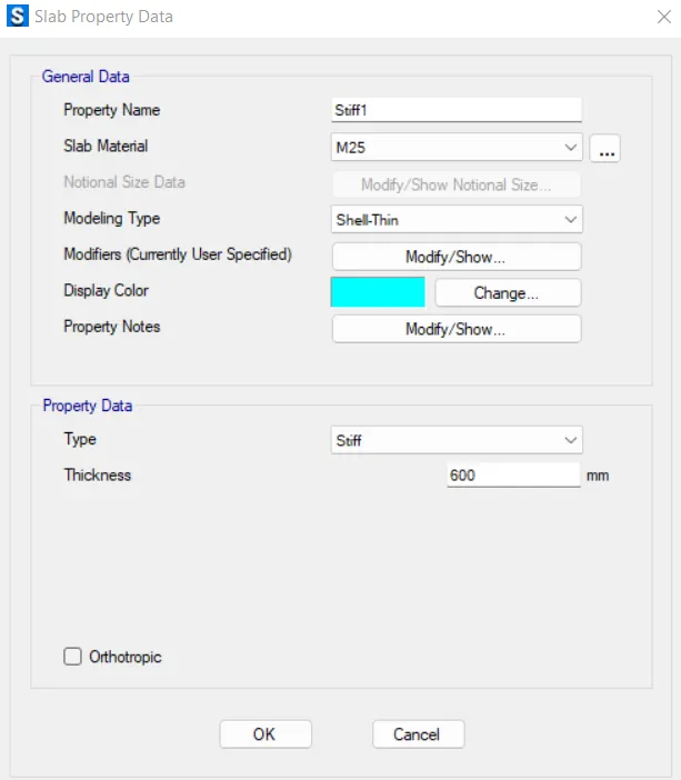
- Define slab property data
- Assign the area spring property
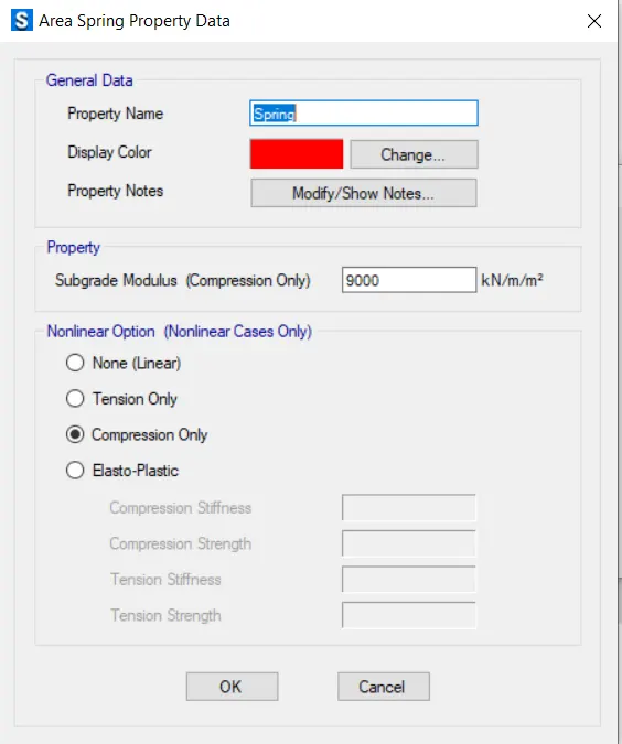
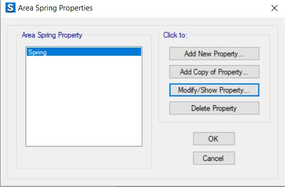
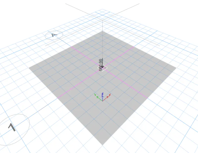
- Assign the load assignment force
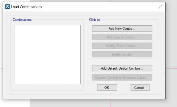
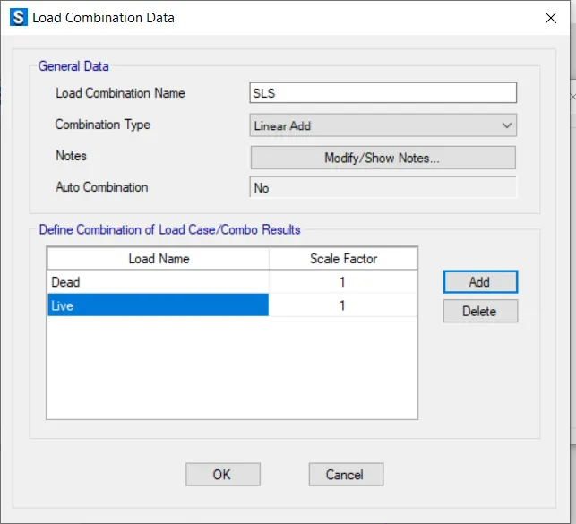
- Define load combinations
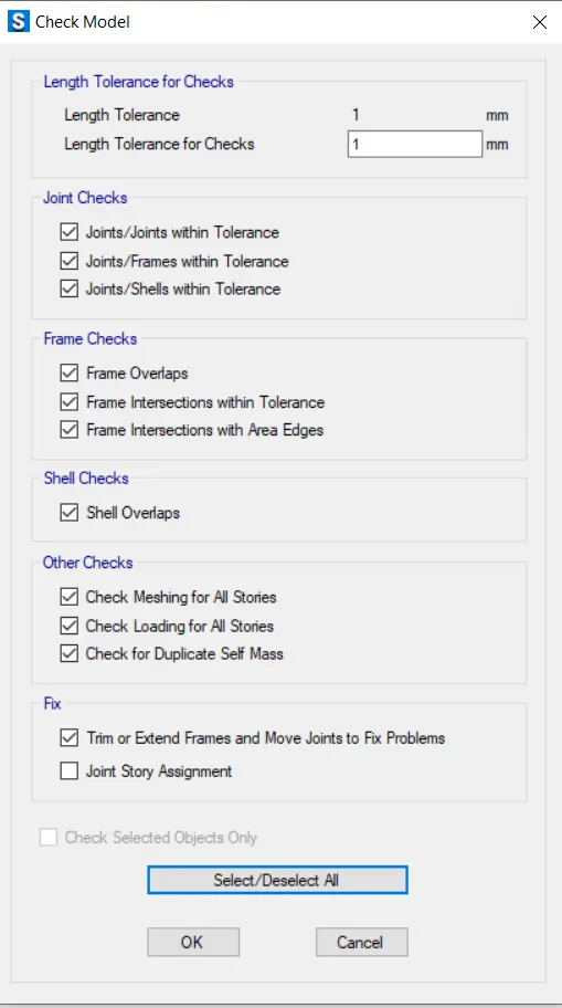
- Check the model

- Run the analysis
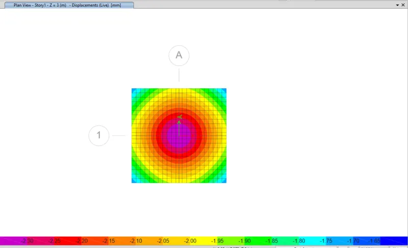
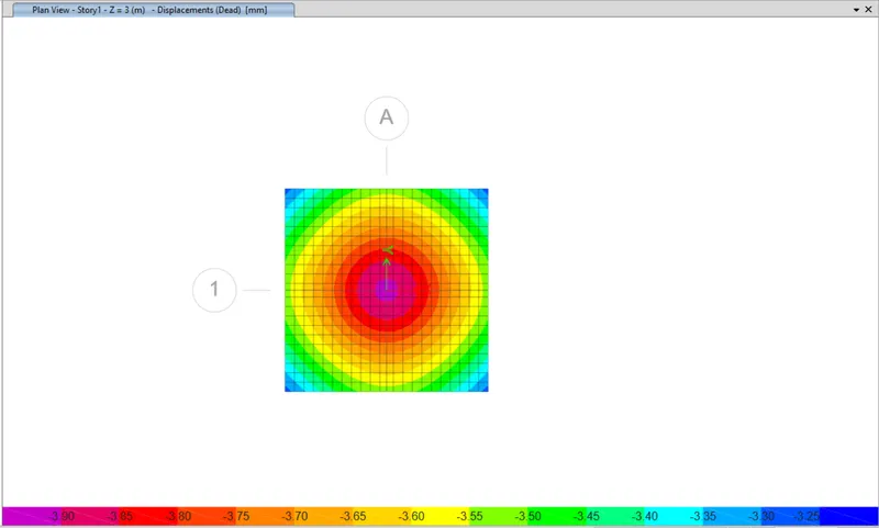
Here the displacement for both dead and live load is within the limit
- Check for bearing pressure under serviceable limit stage
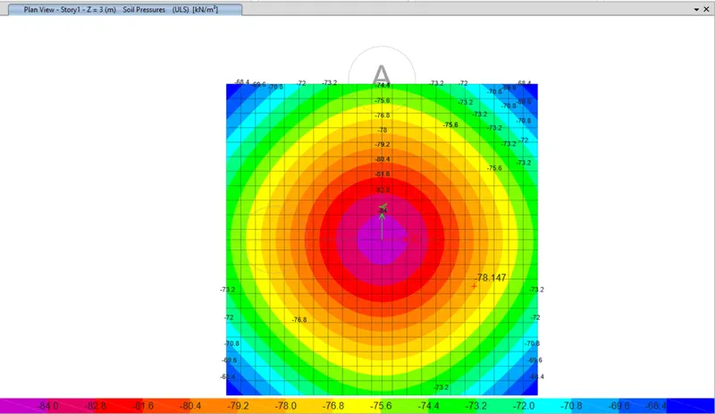
Here the maximum soil bearing pressure is 84 KN/m^2 within the permissible limit i.e. 150 KN/m^2
- Again unlock the model
- Create design strip for design footing
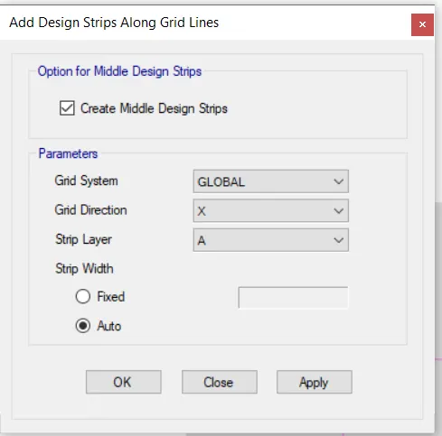
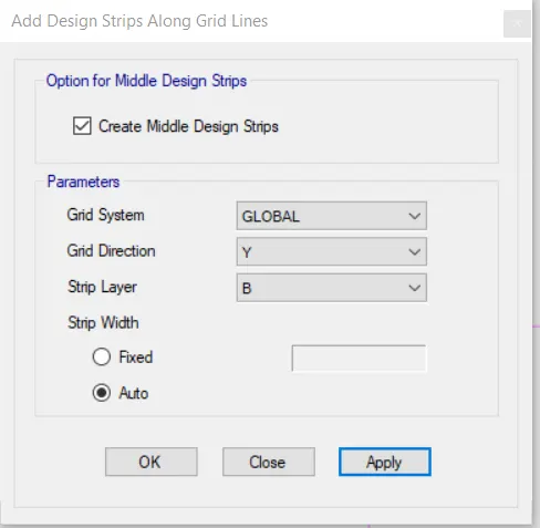
- Again run the analysis
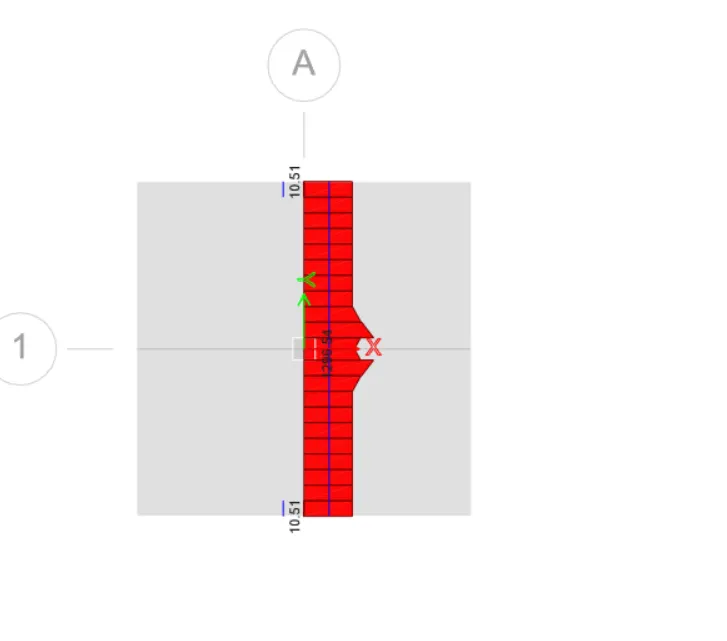
- Check the flexural reinforcement
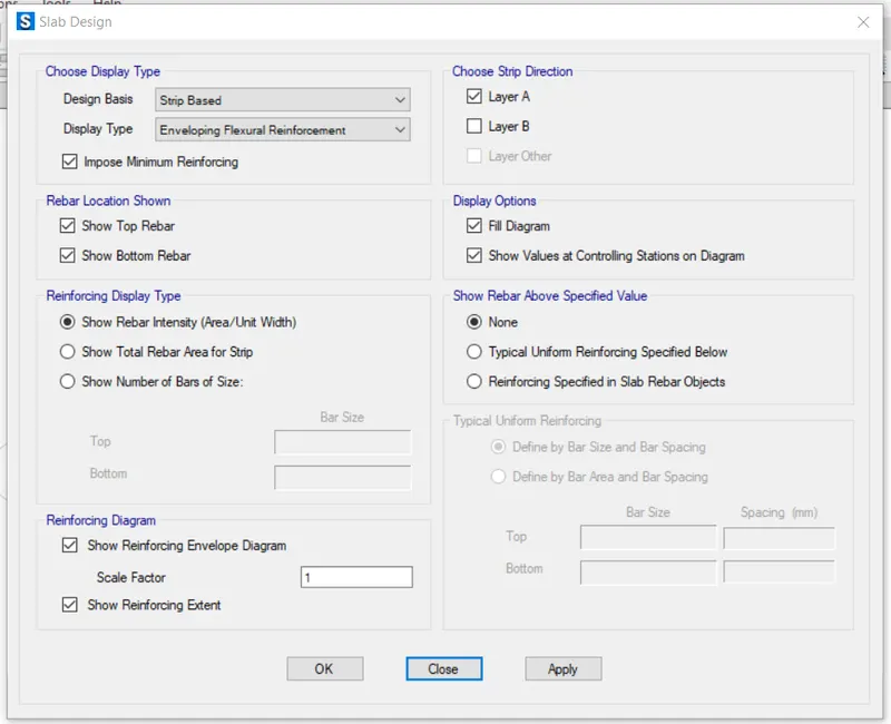
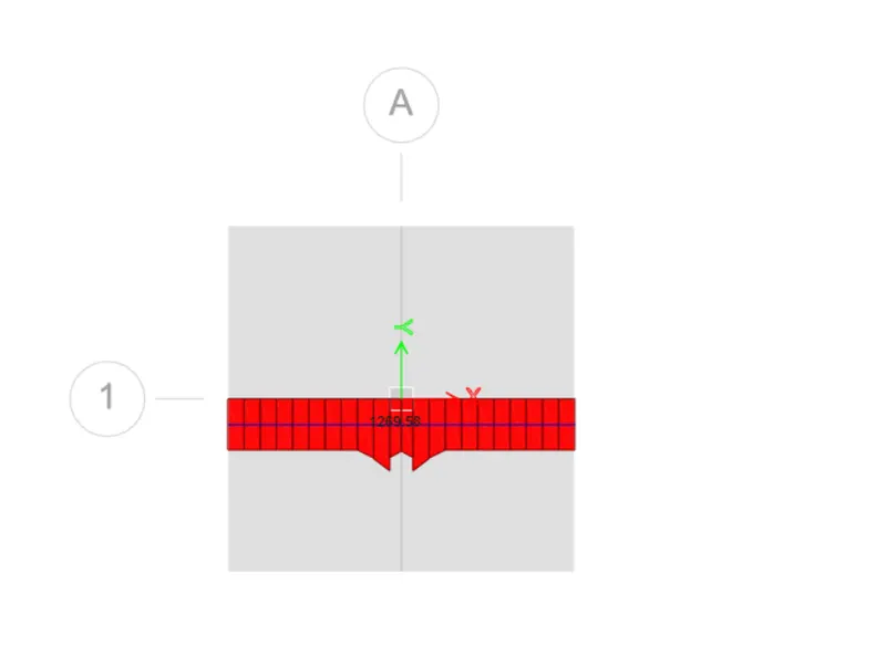
Here the maximum reinforcement is 1269.58 mm^2 per metre
- Check for punching shear
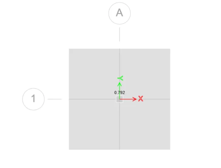
Punching shear is 0.792 N/mm^2 which is less than 1. Hence it is safe.
RESULTS:-
Isolated footing has been analysed by using SAFE software.
Q.2. A column of size 600x600 carrying an unfactored gravity load (DL+LL) of 1175 KN is to be supported on pile cap, which ultimately transfers load to the piles underneath. Piles of 16 metres length and 500 mm diameter are to be used. Each pile has a load carrying capacity of 200 KN. Model, analyse and design the pile cap on SAFE to evaluate the following:
- Pile group to be used
- Depth of pile cap
- Longitudinal steel on top and bottom face in both directions
Ans=
AIM :- To Model, analyze and design the pile cap on SAFE to evaluate the following:
-Pile group to be used
-Depth of pile cap
-Longitudinal steel on top and bottom face in both direction
Finally to check the following details as per IS 2911 and SP-34.
1) Check for settlement (Unfactored load) [SLS] (Serviceability limit state) (Limited to 50mm).
2) Check for soil pressure (Unfactored load) [SLS] (Serviceability limit state) (should be within safe bearing capacity.
3) Check for two way shear or punching shear (Factored load) [ULS] (Ultimate limit state) which should be less than 1.
4) Checking for reinforcement (Factored) [ULS] (Ultimate limit state). Minimum reinforcement should be 0.12% as per IS-456.
INTRODUCTION:-
Axial load = 1175KN
Length of piles 16m
Diameter of pile = 500mm
Pile capacity = 200KN
No of piles = 1175/200 = 5.875 = Assume 8 piles
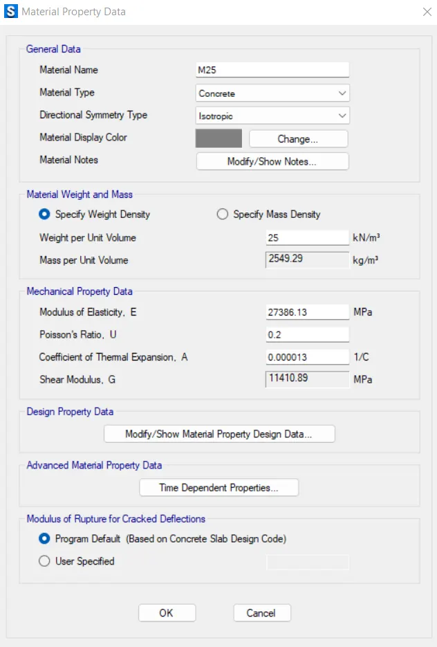
Assume grade of concrete is M25
Area of each pile = π4(d2)π4(d2) = π4(5002)π4(5002) = 196349.5mm2
E = 5000√fckfck = 25000
Spring constant (k) = EA/L = (25000 x 196349.5)/16000 = 306796.09 N/mm = 306796.09 Kn/m
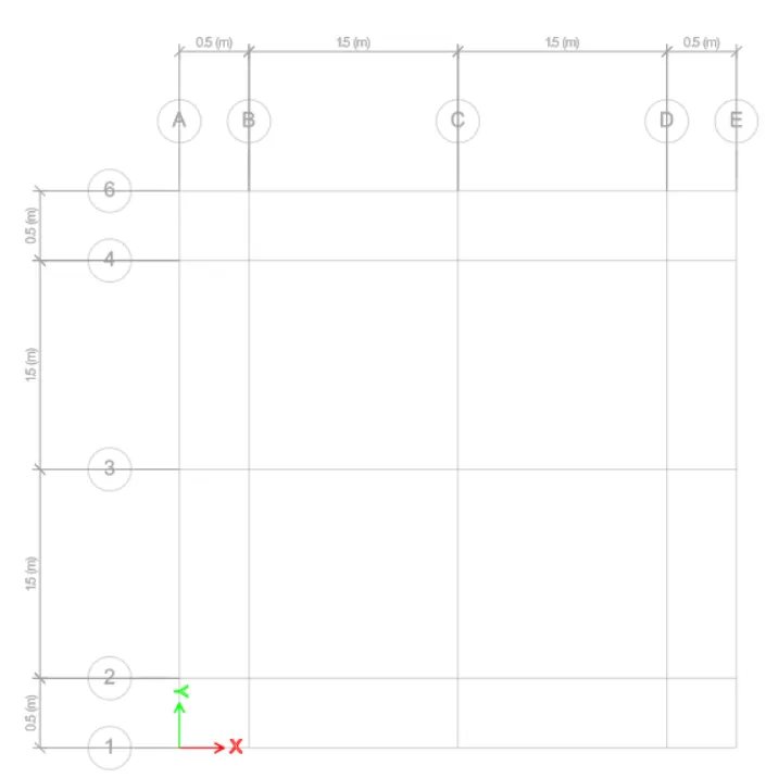
Take center to center distance between piles= 3 X Pile diameter(500mm) = 1500mm, edge spacing = 500mm
Assume pile cap depth = 1000mm
Length = 4000m and Width = 4000mm
PROCEDURE:-
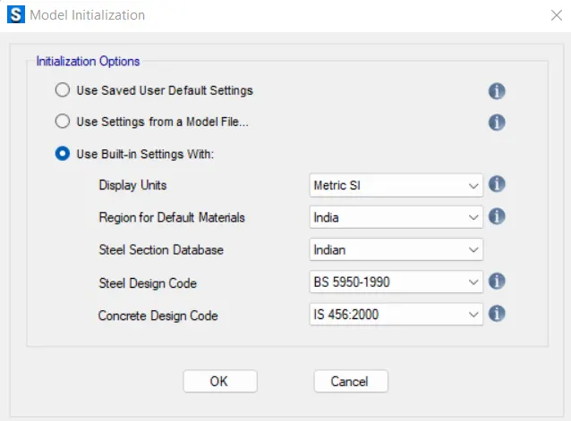
- Open new model and define coda provisions
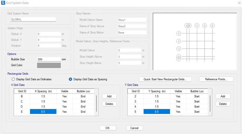
Define material property
Assign pile1 to every piles
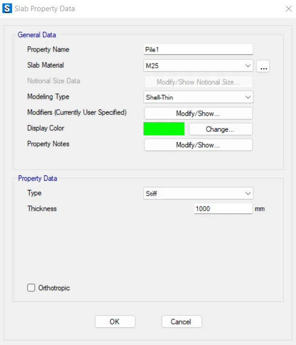
Assign slab1 to pile cap
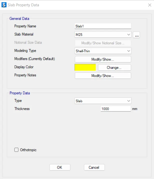
Assign stiff1 to column
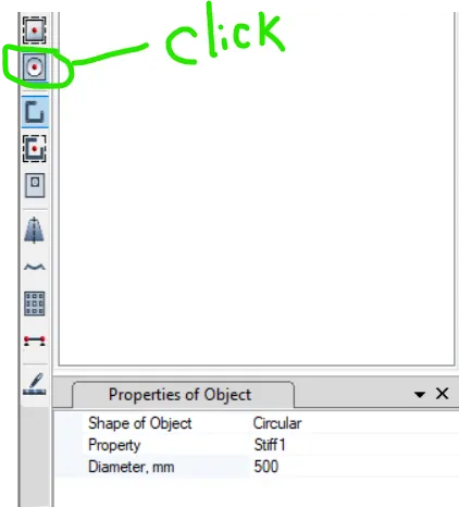
Click to quick draw area and draw piles of dia 500MM
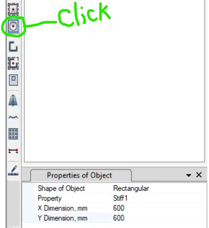
Now draw the center column of 600MM X 600MM size
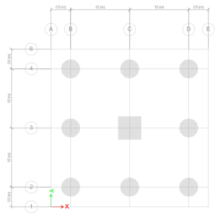
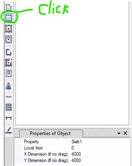
Draw the pile cap of size 4000MM X 4000MM
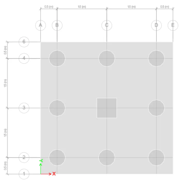
Go to draw tab and then draw points tab
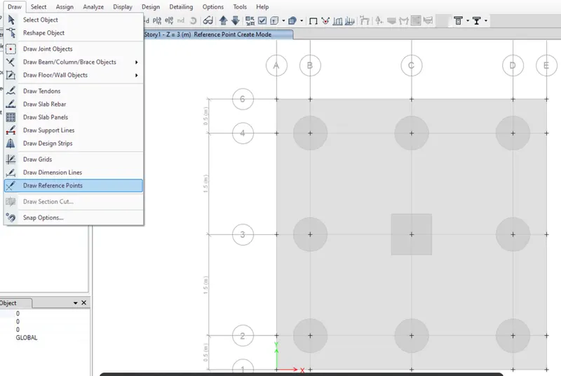
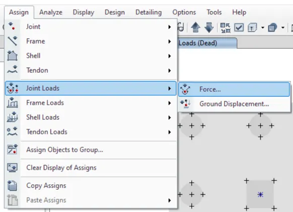
select the central point in column and assign the load
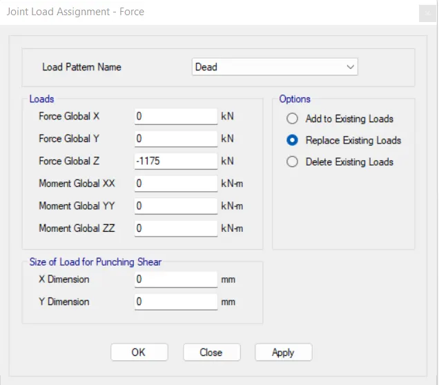
First assign the dead load -1175
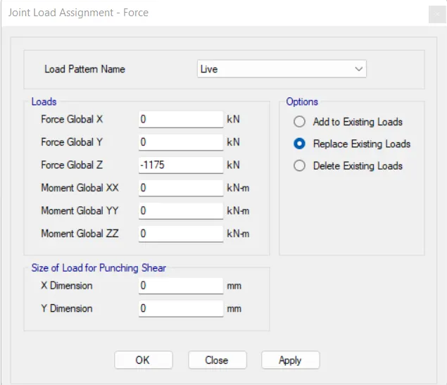
Then assign the live load of 1175KN
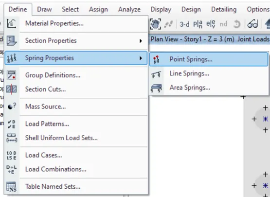
Define the point spring property
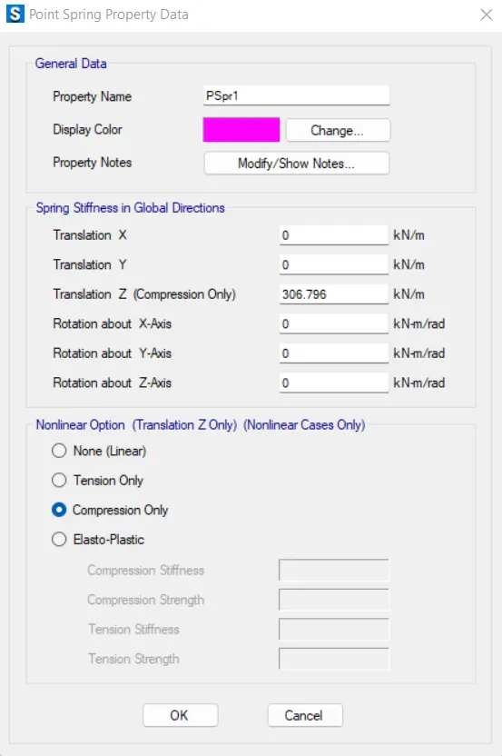
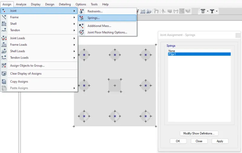
Then assign the point spring property over the each pile
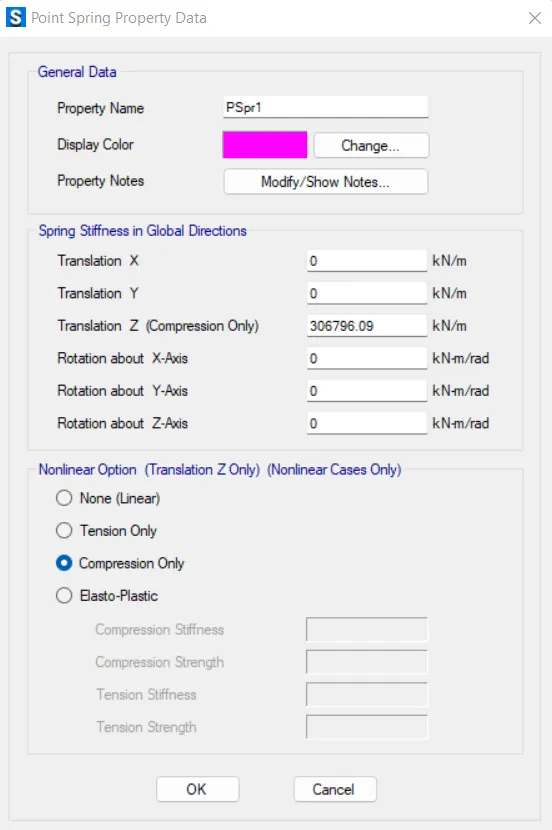
Define the load combinations
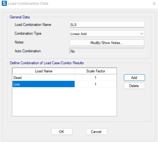
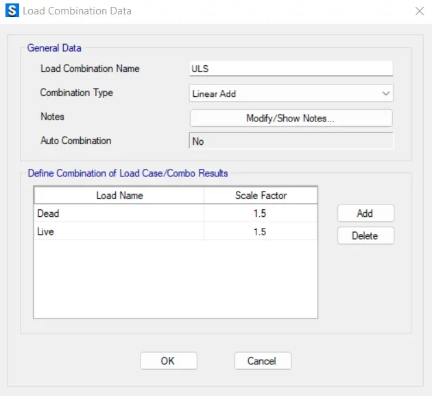
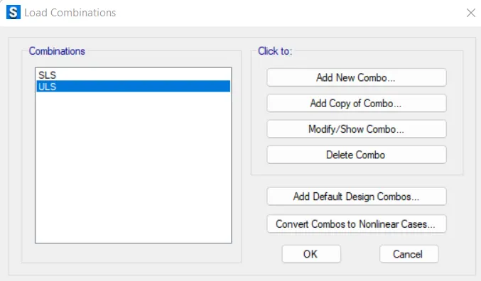
Assign the load combination to Ultimate limit state
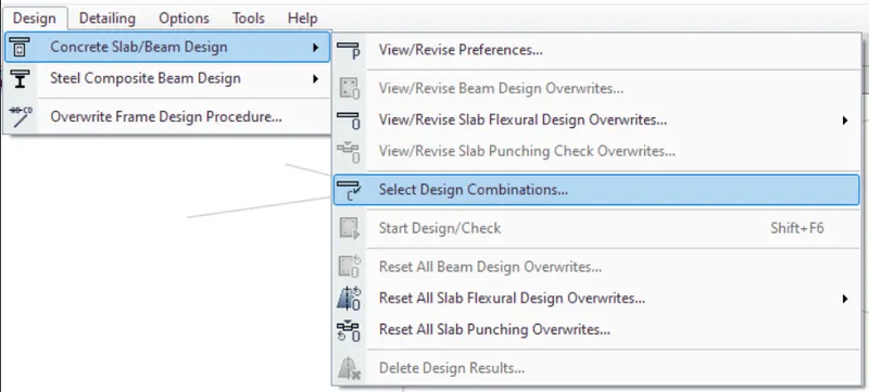
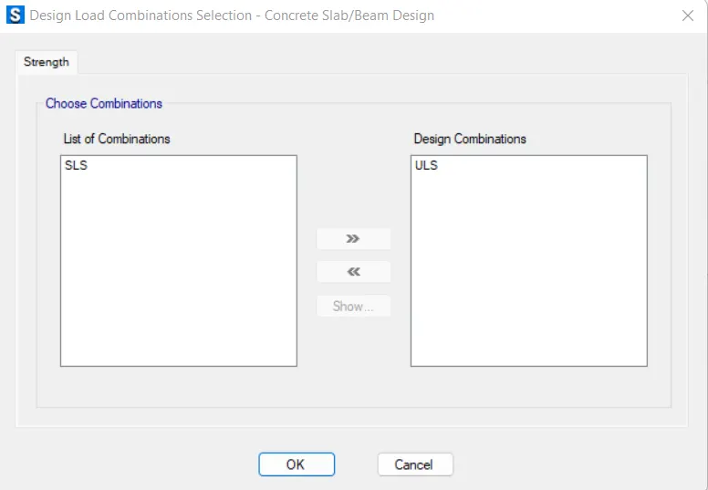
Draw the design strips
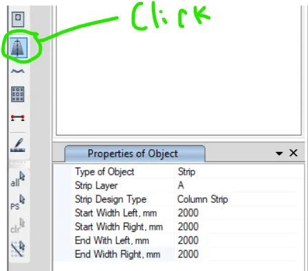
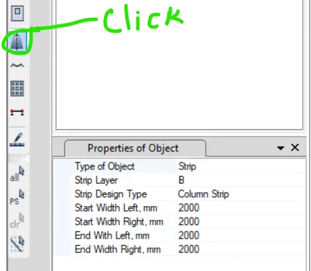
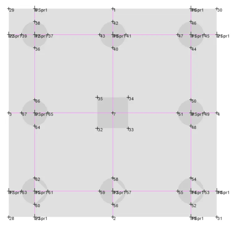
Do a mesh check and set it to 0.1m before running the analysis-
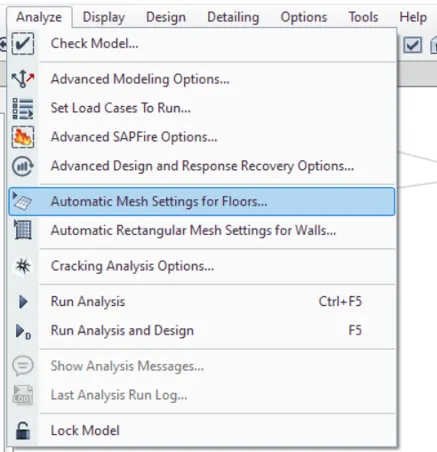
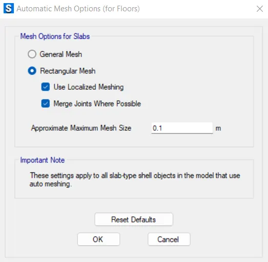
Go to analysis tab and click check model

Run the analysis.
Results:-
1) Check for settlement (Unfactored load) [SLS] (Serviceability limit state) (Limited to 50mm)
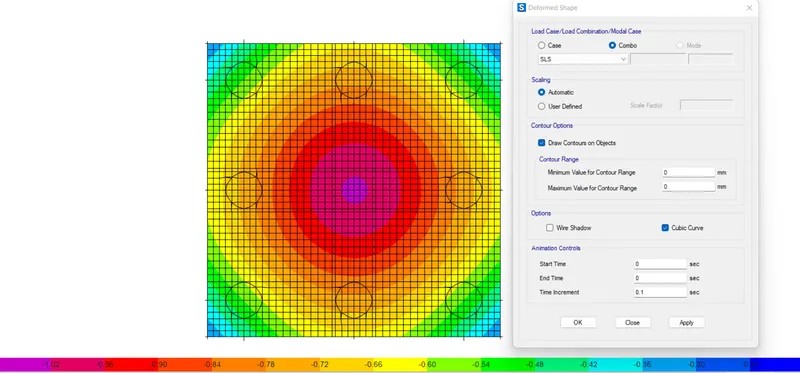
Hence all settlements are under satisfactory limit.
2) Check for soil pressure (Unfactored load) [SLS] (Serviceability limit state) (should be within load bearing capacity of pile which is 200KN.
Click to display support reaction-
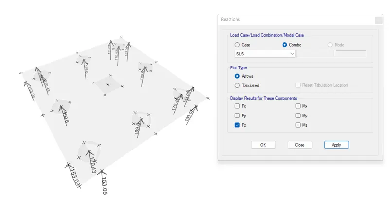
Support reactions are not exceeded safe bearing capacity of pile which is 200KN
3) Check for two way shear or punching shear (Factored load) [ULS] (Ultimate limit state) which should be less than 1.
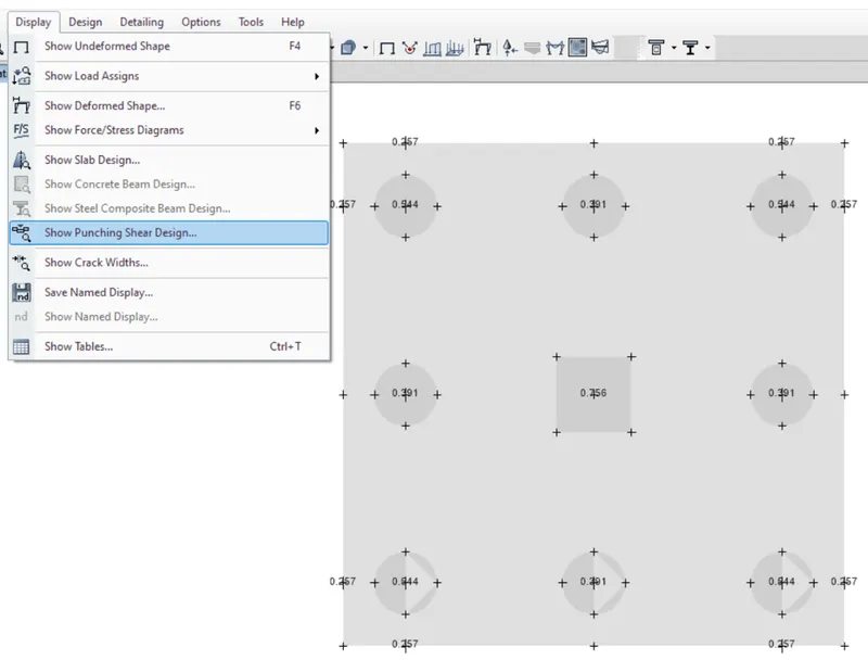
All ratio is less than 1.
Hence okay.
4) Checking for reinforcement (Factored) [ULS] (Ultimate limit state). Minimum reinforcement should be 0.12% as per IS-456.