Flow over an airfoil
Aim:
- To model the flow over the Naca0017 airfoil.
- To perform the flow simulation at different angles of attack.
- To compare the lift and drag forces.
Introduction:
Computational fluid dynamics (CFD) is a branch of fluid mechanics that uses numerical analysis and data structures to analyze and solve problems that involve fluid flows. Computers are used to perform the calculations required to simulate the free-stream flow of the fluid, and the interaction of the fluid (liquids and gases) with surfaces defined by boundary conditions.
Here Solidworks flow simulation is used for simulation.
Theory:
The NACA airfoils are airfoil shapes for aircraft wings developed by the National Advisory Committee for Aeronautics (NACA). The shape of the NACA airfoils is described using a series of digits following the word "NACA". The parameters in the numerical code can be entered into equations to precisely generate the cross-section of the airfoil and calculate its properties.
The NACA four-digit wing sections define the profile by:
1. First digit describing maximum camber as percentage of the chord.
2. Second digit describing the distance of maximum camber from the airfoil leading edge in tenths of the chord.
3. Last two digits describing maximum thickness of the airfoil as percent of the chord.
Input datas:
- Air foil design is of Naca0017.
- Attack angles be 0, 2, 4, 6, 8, 10.
- Type of flow is external.
- Simulation is time dependent having flow time 5sec and the output will be obtained for every 1sec.
- Fluid is air.
- Flow velocity is in positive x axis at 600 m/s.
- length of the chord is 1m(approx)
- Surface force along x direction is drag force.
- Surface force along y direction is lift force.
Results:
Angle of attack 0deg
3d model
simulation
Angle of attack 2deg
3d model
simulation
Angle of attack 4deg
3d model
simulation
Angle of attack 6deg
3d model
simulation
Angle of attack 8deg
3d model
simulation
Angle of attack 10deg
3d model
simulation
Observations:
| Angle of attack | Drag force in Newton (average) | Lift force in Newton (averrage) |
| 0 | 316.1 | 0.66 |
| 2 | 323.8 | 830.45 |
| 4 | 434.21 | 1672.36 |
| 6 | 554.79 | 2501.25 |
| 8 | 752.033 | 3245.12 |
| 10 | 998.53 | 4014.98 |
Plots obtained:
drag force vs Angle of attack
Angle of attack vs lift force
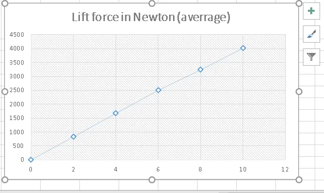
Drag force vs lift force
Setup Explanation:
- Data file for NACA0017 is downloaded from the trusted sites.
- XYZ curve is drawn using the obtained data files.
- New flow simulation created as external flow with above said input datas.
- Global mesh and local mesh is created.
- Cutplots is created.
- Run the flow simulation.
- Obatined values are noted.
- Alter the angle of attack to 2,4, 6, 8, 10 and do the simulation again
- Note the obtained drag forces and lift forces values.
- Export the results to excel file and draw the required plots.
Conclusion:
- From the plots it is clear that Lift force increases with angle of attack.
- From the plots it is clear that drag force increases with angle of attack.
- computational domain is provided *10 times the length of cord(1m) on both sides of the axis.
- Both the drag force and lift force is only incresing gradually.
- At 0 degree the lift force is not seems to significant to consider.