CFD analysis of Flow over an airfoil(NACA0017 airfoil)
CFD analysis of Flow over an airfoil(NACA0017 airfoil)
You can use any Airfoil from the AirFoil Data Base. While copying the Airfoil data to a text file, make sure that you format it in a way that Solidworks can read it. A sample file is attached in the link below,
Click Here to download the sample airfoil Data.
CFD:
Computational fluid dynamics is a branch of fluid mechanics that uses numerical analysis and algorithms to solve fluid flow situations. High-performing computers are used to conduct the calculations required to simulate the interaction of liquids and gases with surfaces defined by boundary conditions.
AIRFOIL
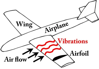
An airfoil or aerofoil is the cross-sectional shape of a wing, blade, or sail. An airfoil-shaped body moving through a fluid produces an aerodynamic force. The component of this force perpendicular to the direction of motion is called lift. The component parallel to the direction of motion is called drag.
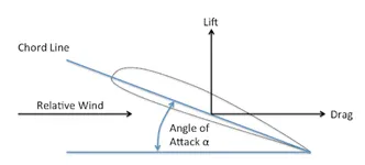
CAMBER LINE: A-line joining the leading and trailing edges of an airfoil equidistant from the upper and lower surfaces. The mean camber line determines the characteristics of the airfoil. Also known as a camber line or a mean line.
CHORD LINE: In aeronautics, a chord is the imaginary straight line joining the leading edge and trailing edge of an aerofoil. The chord length is the distance between the trailing edge and the point where the chord intersects the leading edge.
PROCEDURE :
In this report, flow over a NACA airfoil has been simulated at different angles of attack. Our main aim was to determine and compare the drag force ( X-direction ) and the lifting force ( Y-direction ) on the airfoil at different angles of attack ( 0,2,4,6,8,10). The simulation was done using SolidWorks flow simulation.
Starting with the Flow Simulation –
Create a new wizard for every case. Use the default unit system. Next, select the eternal flow as we are doing external flow analysis. This study will be time-dependent we will be performing the experiment for a total of 5 sec and the time step will be 1 sec. we are taking air as our working fluid medium. Next, we have to give velocity for this air-flow in the x-direction with a magnitude of 500 m/s.
Computational domain –
We are going for a 2-d simulation in the XY plane.
Meshing and goals -
The basic mesh was looking good so no changes were made. But we have to refine cells at the extruded surface. So to do this we have to add the local mesh. (Select the surface -refining level (3).In this study, we are mainly focusing on the drag and lift forces so we have insert global and surface goals for this.
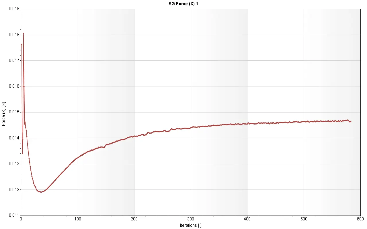
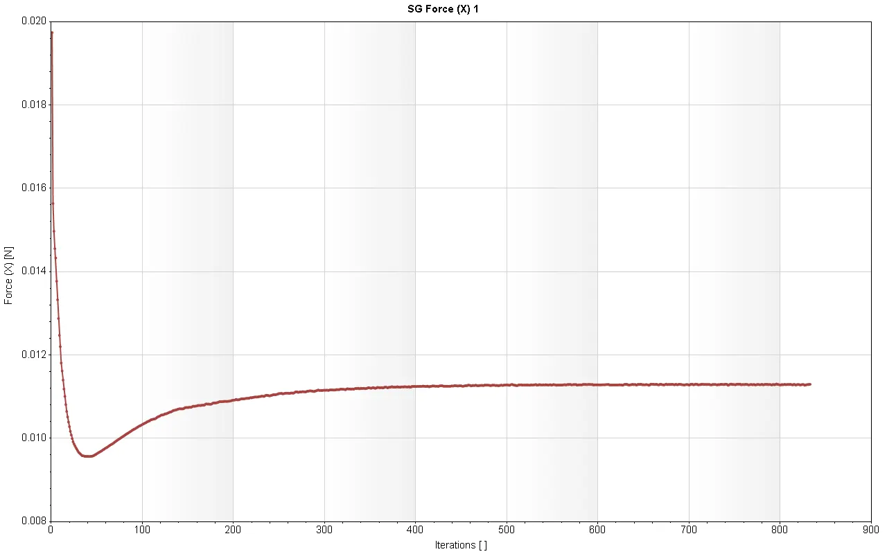
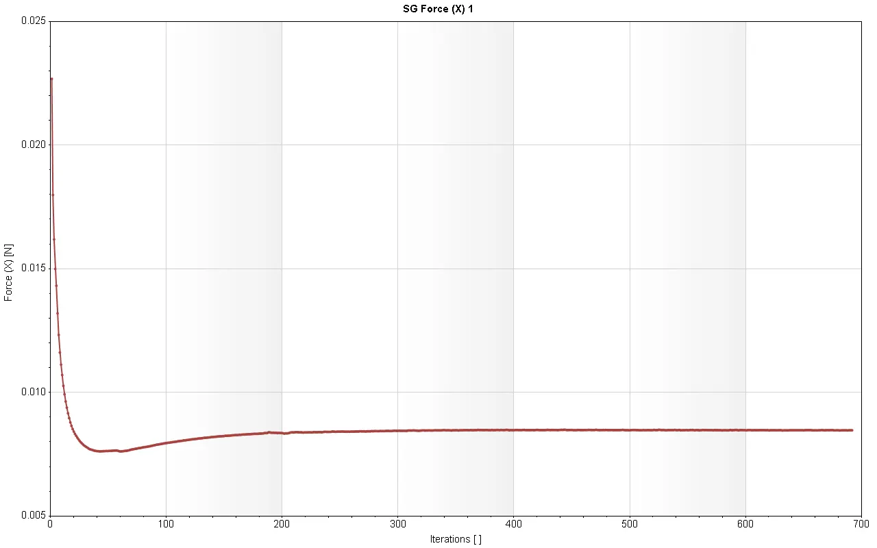
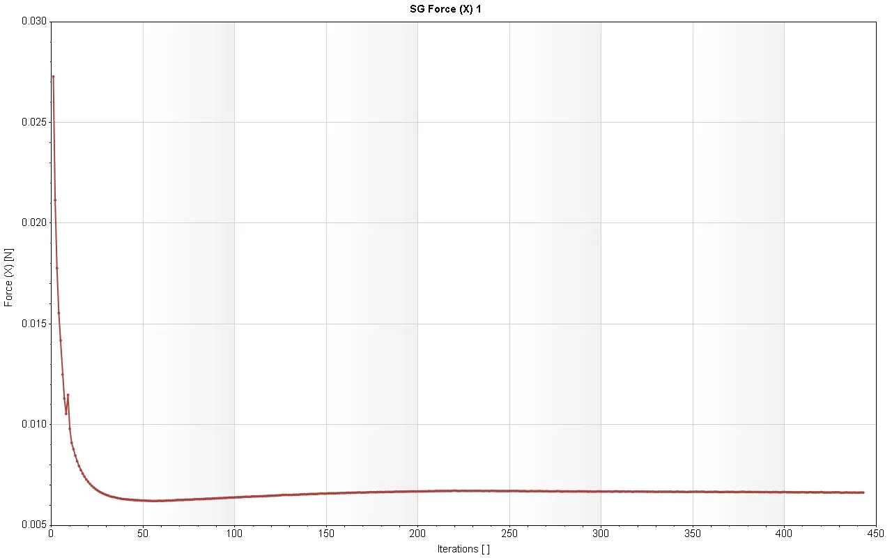
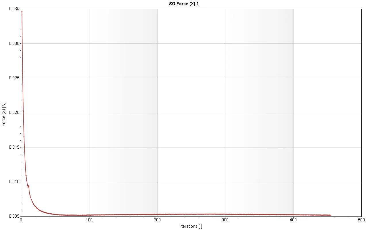
Drag Force: A drag force is the resistance force caused by the motion of a body through a fluid, such as water or air. A drag force acts opposite to the direction of the oncoming flow velocity. This is the relative velocity between the body and the fluid. (SC force in X-Direction)
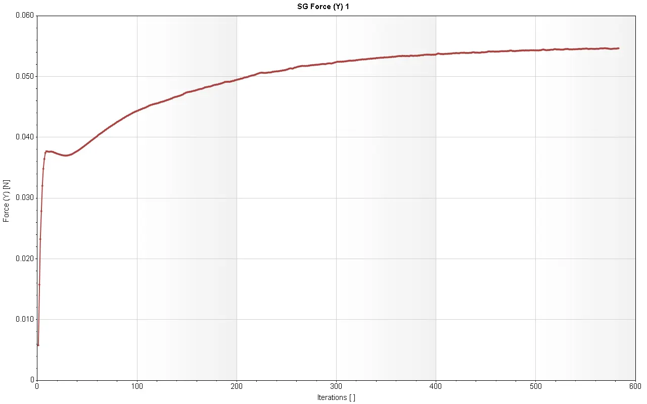
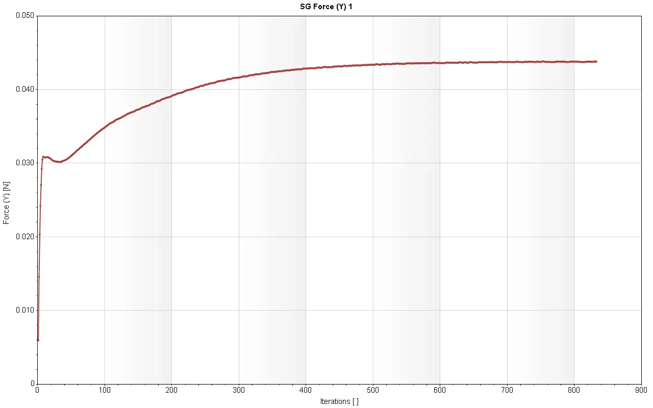
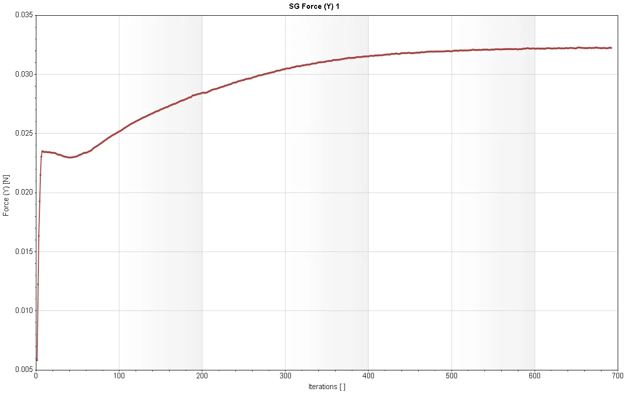
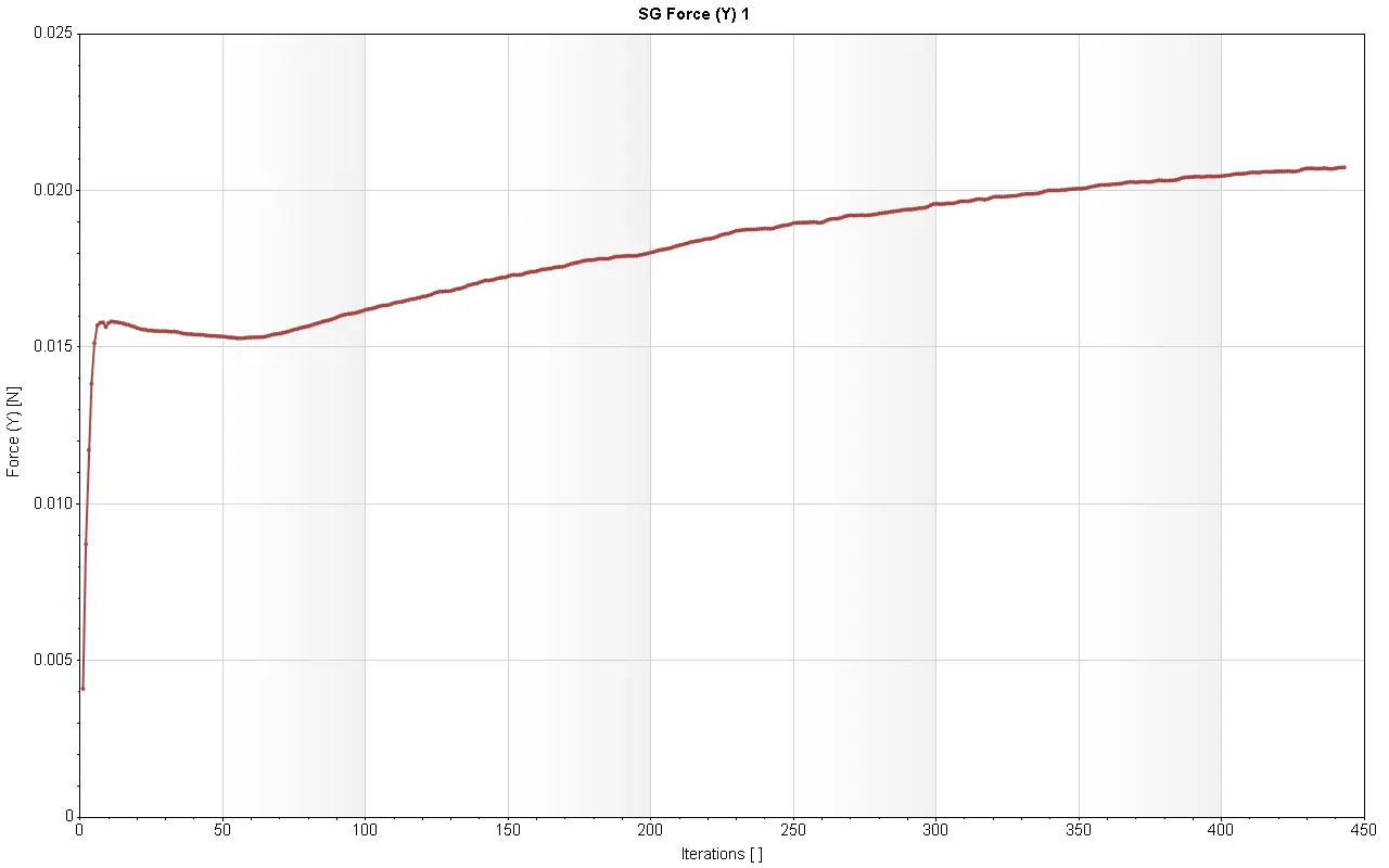
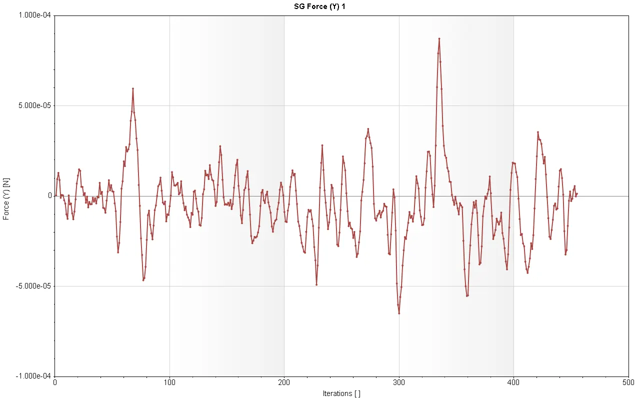
Lift Force: A fluid flowing around the surface of an object exerts a force on it. Lift is the component of this force that is perpendicular to the oncoming flow direction. It contrasts with the drag force, which is the component of the force parallel to the flow direction. (SC force in Y-Direction)
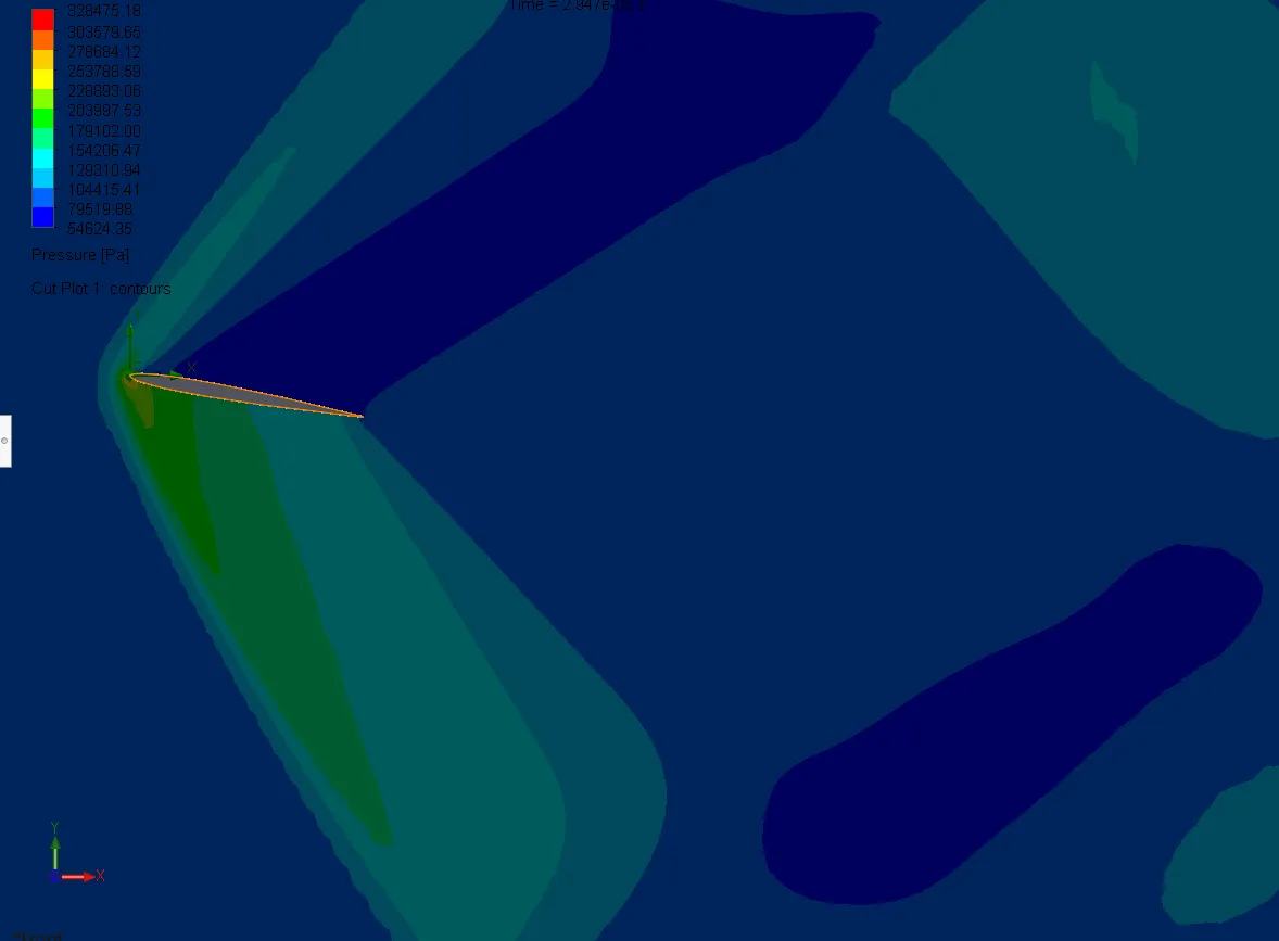
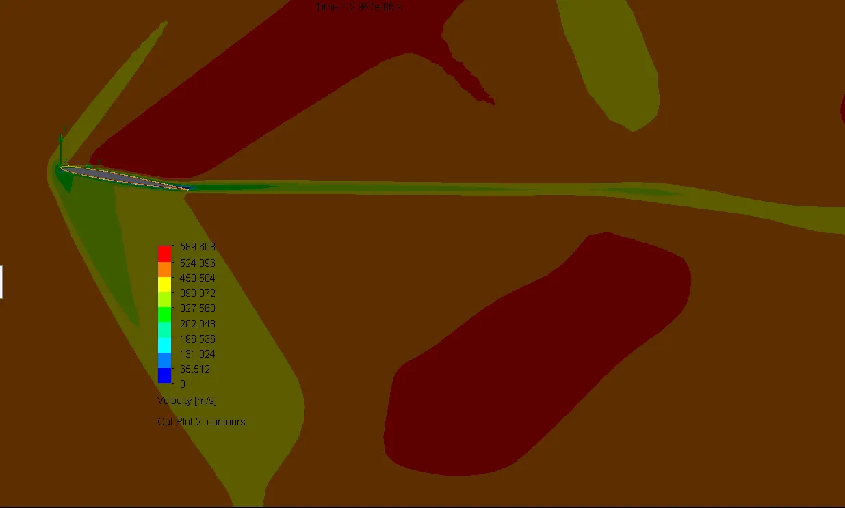
CASE 01: ANGLE OF ATTACK = 10 degrees
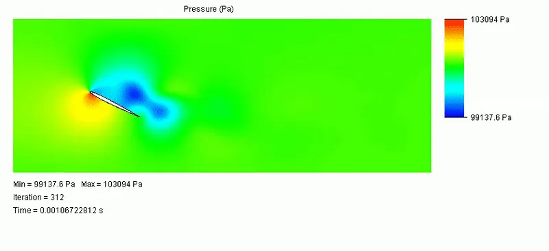
Pressure Plot:
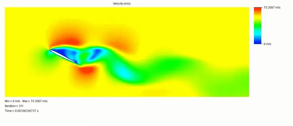
Velocity Plot:
Goal Plots:

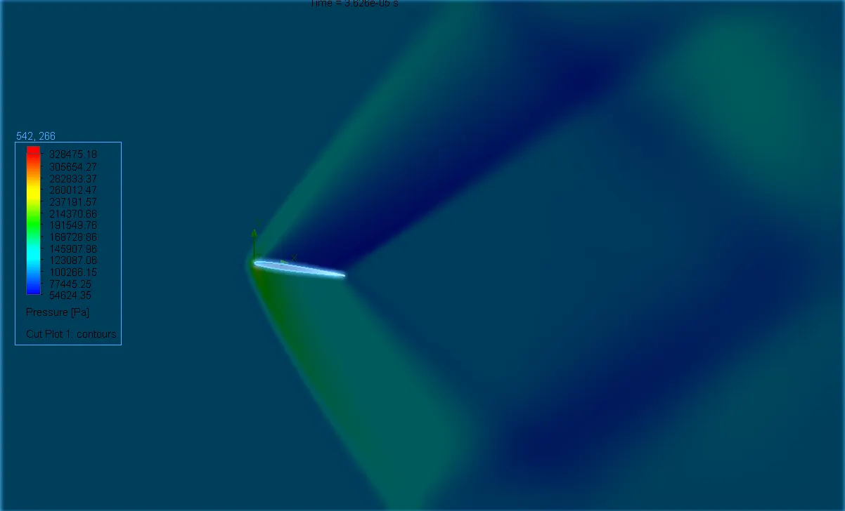
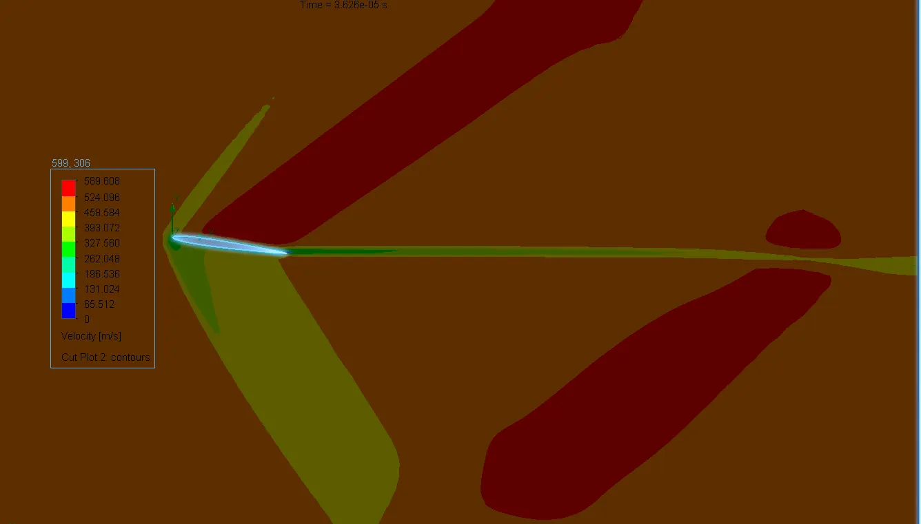
CASE 02: ANGLE OF ATTACK = 8 degrees
Pressure Plot:
Velocity Plot:
Goal Plots:

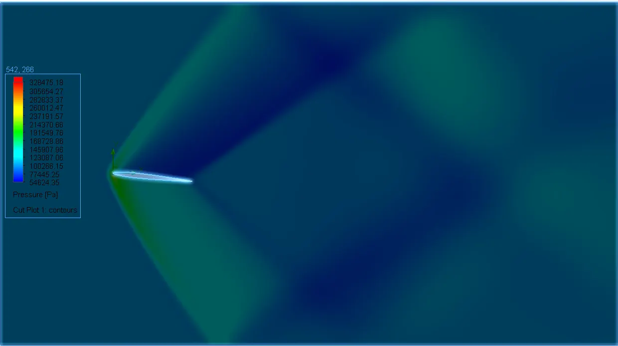
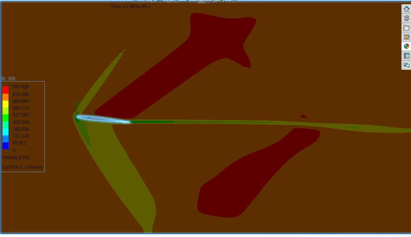
CASE 03: ANGLE OF ATTACK = 6 degrees
Pressure Plot:
Velocity Plot:
Goal Plots:

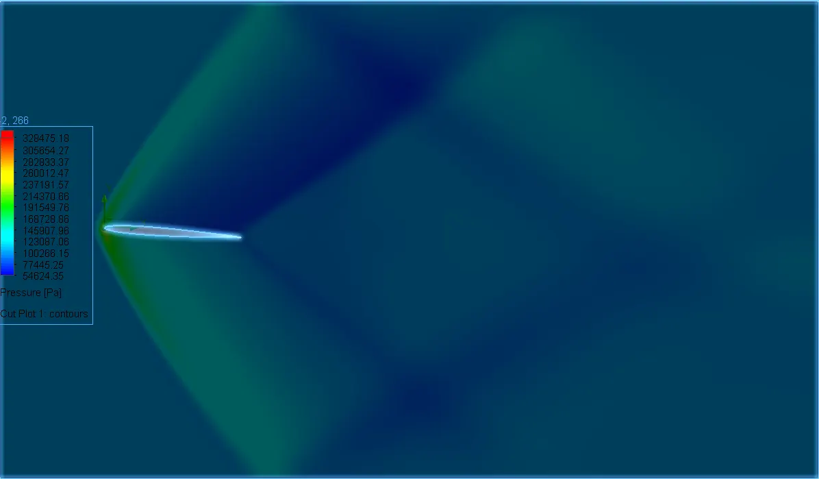
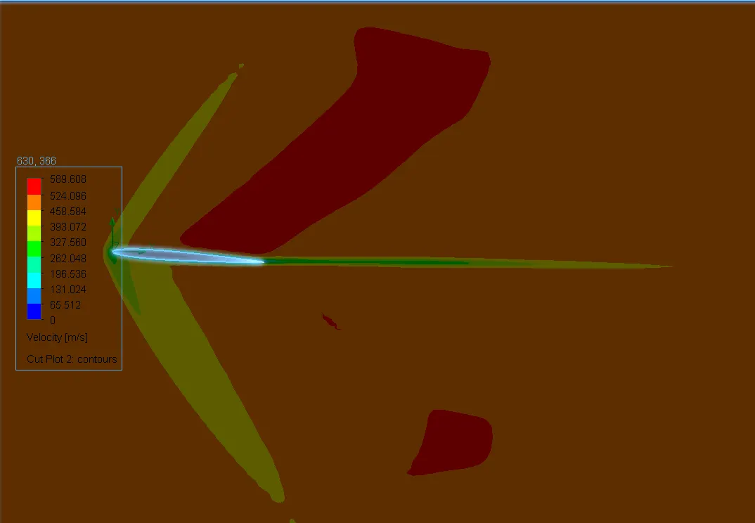
CASE 04: ANGLE OF ATTACK = 4 degrees
Pressure Plot:
Velocity Plot:
Goal Plots:

CASE 05: ANGLE OF ATTACK = 2 degrees
Pressure Plot:
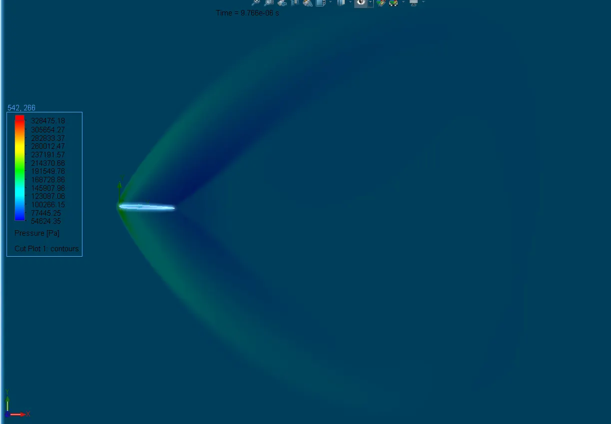
Velocity Plot:
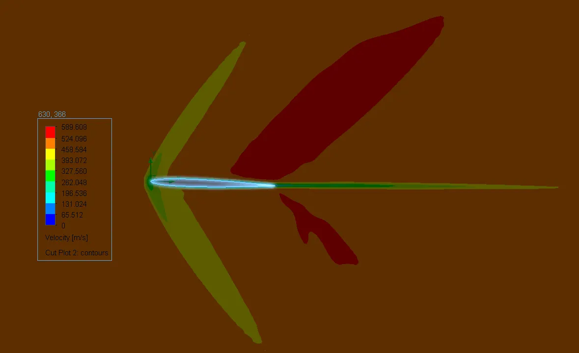
Goal Plots:
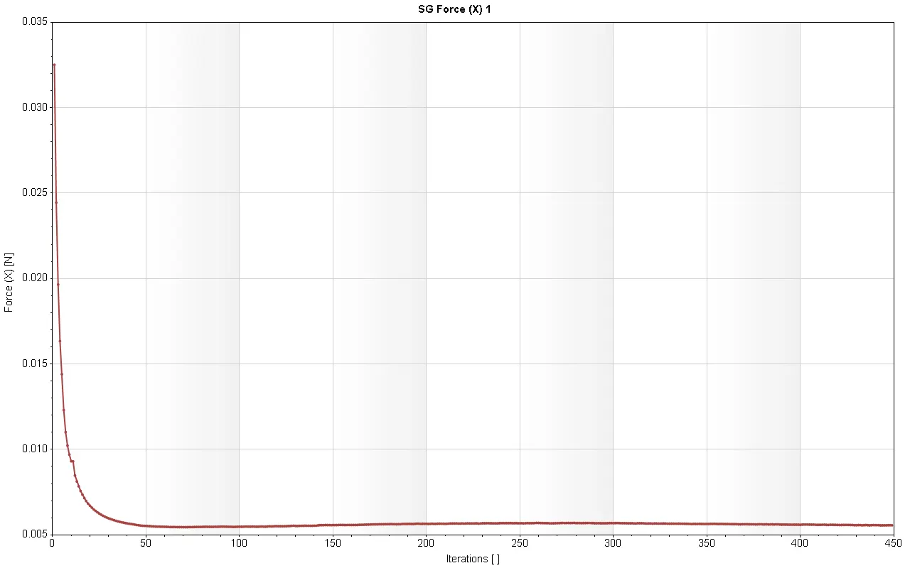
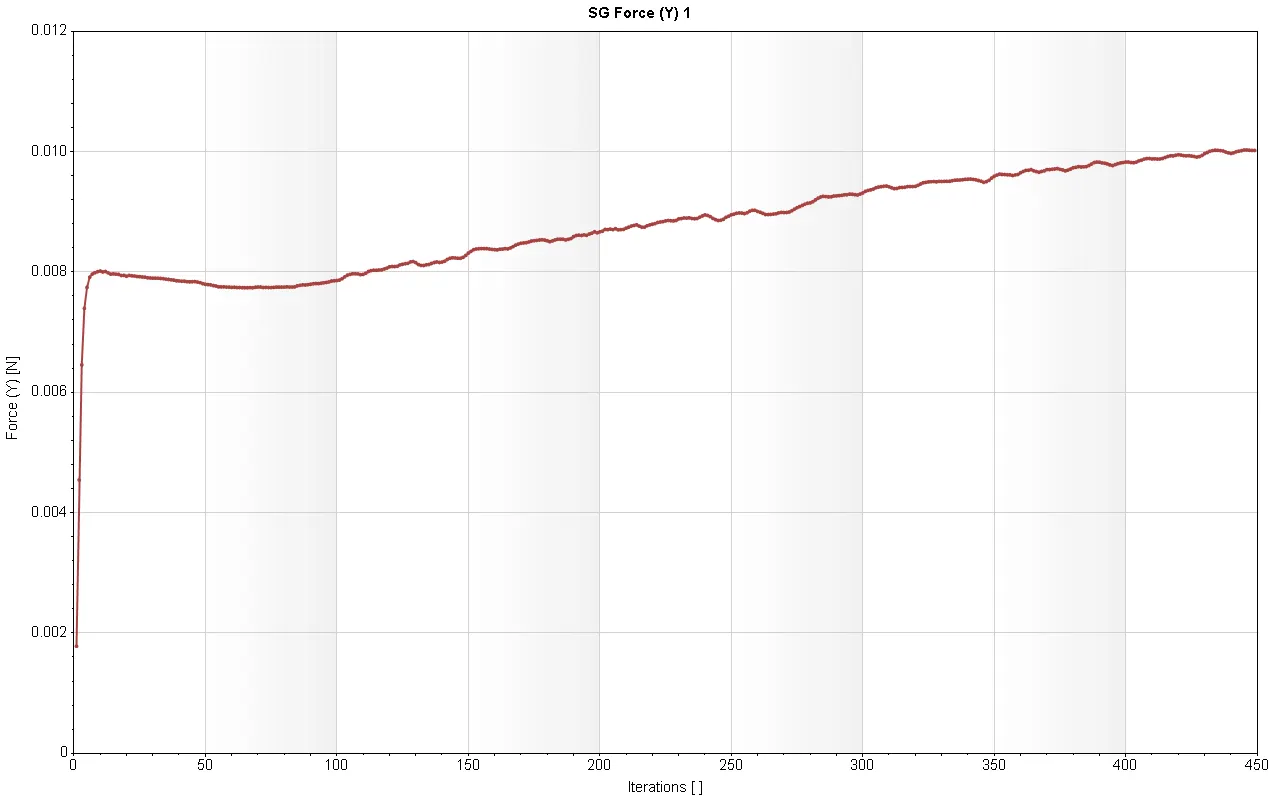

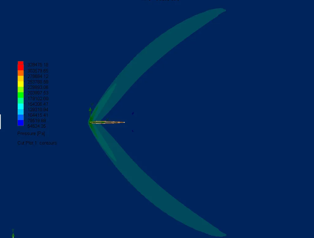
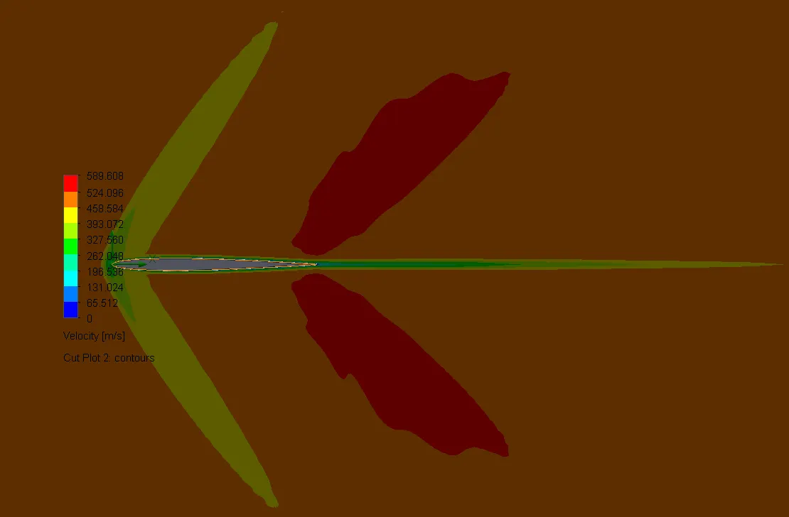
CASE 06: ANGLE OF ATTACK = 0 degrees
Pressure Plot:
Velocity Plot:
Goal Plots:

Conclusion:
- So we can see that as the angle of attack increases the lift force on the surface also increases.
- And overall we can see the increase in the size of the wake region as the angle of attack increases. We can see the change in the position of the stagnation point.