Flow over an airfoil
Aim : To perform airflow simulation over NACA0017 airfoil.
Introduction : An airfoil or an aerofoil is the shape of a wing or blade in cross section. Aerodynamic forces are produced when an airfoil shaped body moves through a fluid. The component of this force perpendicular to the direction of motion is called lift. The component parallel to direction of motion is called drag. These forces depend on the pressure difference above and below the airfoil. In case of airplanes the pressure above the wings airfoil should be less as compared to that of below, this generates a lift force. Opposite of this is required in case of cars.
Airfoils are increasingly being used for different purposes in the both engineering and industry areas .They are made in different sizes and have a wide range of application, from wind turbines to air planes, and so on . In improving design process and achieving a better condition for an airfoil, knowing the performance plays a crucial role. The below fig. shows a labelled diagram of an airfoil.
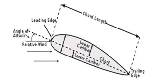
This project performs simulation studies on NACA0017 airfoil to estimate the effects of change in angle of attacks on the drag and lift forces.
The airfoil used in this project -NACA0017:
0 - Max Camber (%)
0 - Max camber position (%)
17 - Thickness (%)
Procedure :
• Import the curve of NACA0017 airfoil from “Airfoil Tools”.
• Convert the entity and close the curve with the help of a line. Perform extrusion to create the airfoil.
• Save the file. Open flow simulation, select wizard in order to create a new flow simulation project.
• Set the required units, external flow, select the fluid medium, Transient phenomenon and velocity along x-axis.
• Now adjust the computational domain. The simulation is performed along X-Y plane. Expand the domain box such that the space after the airfoil is it is 10 to 15 times the length of the airfoil.
• Provide local mesh on surface by selecting the surface.
• Set global and surface goals. Select Forces along X and Y direction.
• Run the calculations and load the results. The results can be visualized using the required cut plots and animation can also be generated.
Results :
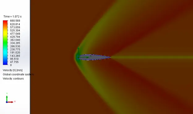
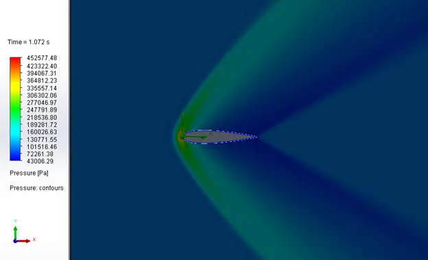
Case 1 : Angle of attack 0°
Velocity :
Pressure :

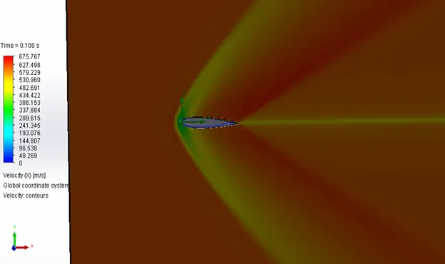
Case 2 : Angle of attack 2°
Velocity :
Pressure :
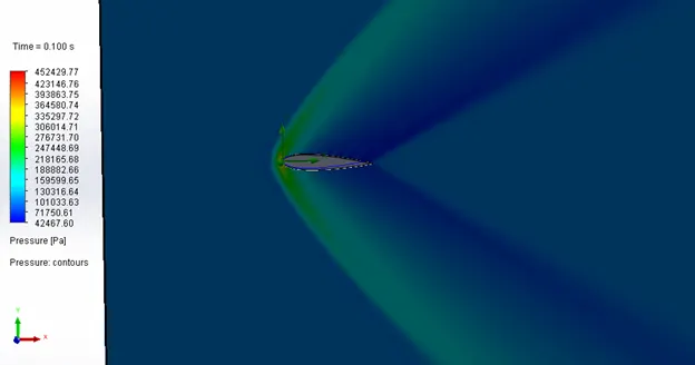

Case 3 : Angle of attack 4°
Velocity :
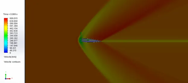
Pressure :
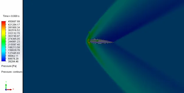

Case 4: Angle of attack 6°
Velocity :
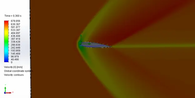
Pressure :
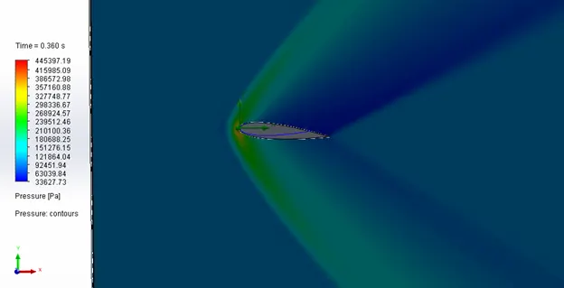

Case 5: Angle of attack 8° :
Velocity :
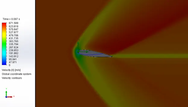
Pressure :
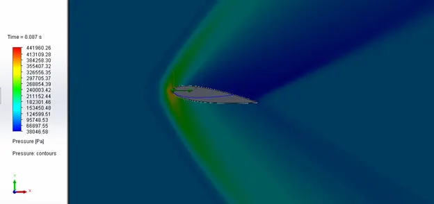

Case 6: Angle of attack 10° :
Velocity :
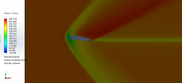
Pressure :
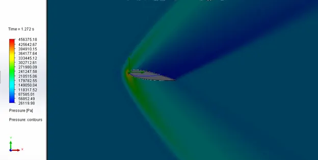

Animation link for case 6 :
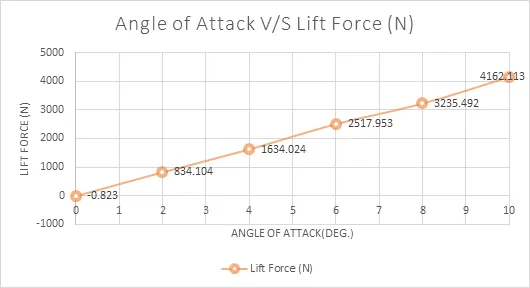
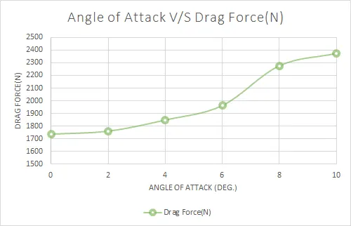
Comparison of Plots :
Inference :
• The increase in angle of attack reduces the pressure above the airfoil and hence the lift force increases with the increase in the angle of attack.
• In the same way with increase in the angle of attack the drag force also increases.
• The wake region increases with increase in the angle of attack.
• When angle of attack is 0° the lift force is close to zero and has symmetric results for both velocity and pressure profile.