FINAL TEST
PFI ENGINE
Q1. What is the Compression ratio for the engine?
Compression ratio is defined as the ratio of the maximum to minimum volume in the cylinder of an internal combustion engine.
Compression ratio of an engine = Maximum volume of the cylinder / Minimum volume of the cylinder
Let compression ratio =rc = Vmax / Vmin = (Vd+ Vc)/ Vc
Where
Vc = clearance volume
Vd = Displacement volume / Swept volume
A High compression ratio id desirable because it allows an engine to extract more mechanical energy from a given mass of air fuel mixture due to its high thermal efficiency. This occurs because internal combustion engines are basically heat engines and higher efficiency is created because higher compression ratio permits the same combustion temperature to be reached with less fuel, While giving a longer expansion cycle, Creating more mechanical power output and lowering the exhaust temperature .
Q2. Modify the compression ratio for this engine to 10.3 without changing geometrical parameters.
To modify the compression ratio of an engine without changing its geometrical parameters is possible only by changing its clearance volume or displacement / Swept volume.
Let us consider varying displacement volume and keeping the clearance volume constant so as to achieve 10.3 compression ratio .
Wkt for the PFI Engine
V max = 5.74 X 10⁻⁴ and
V min = 5.70 X 10-5 = Vc
Also
Vmax = Vd + Vc
Vd = Vmax – Vc
Vd = 5.74 X 10⁻⁴ – 5.70 X 10⁻⁵
Vd = 5.17 X 10⁻⁴ m^3
Now let us vary clearance volume and keeping displacement volume as constant so as to obtain 10.3 Compression ratio.
Rc = V max / V min = 10.3
Upon substituting the values to the above equation
We get
New clearance volume Vc= 555 X 10-5
b)Let us consider keeping constant displacement volume and carrying the clearance volume constant so as to achieve 10.3 compression ratio
In the above eq the value of Vc = 5.70 X 10⁻⁵
New displacement volume , Vd = 5.336 X 10⁻³
Now by using any of the two methods we can get a compression ratio of 10.3
Q3. Calculate Volumetric Efficiency for this engine
Volumetric efficiency in an internal combustion engine design refers to the efficiency with which the engine can move the charge of fuel and air into and out of the cylinders .It also denotes the ratio of air volume drawn into the cylinder to the cylinders swept volume.More specifically , volumetric efficiency is a ratio of mass of air and fuel that is trapped by the cylinder during induction divided by the mass that would occupy the displaced volume if the density in the cylinder were equal to the ambient air density
The volumetric efficiency is defined as the ratio of volume of air sucked into the cylinder during intake stroke to the displacement volume
Volumetric efficiency = ( Va / Vd ) X 100
Displacement volume found previously were equal to 5.17 X 10⁻⁴ m^3
To find the amount of air sucked into the cylinder during intake stroke ,assuming the air used is ideal in nature
Now by ideal gas equation
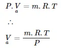
Where
P = Pressure of air at atmospheric conditions = 101325 Nm-2
m = Mass of the air
R = Universal gas constant
T = Temperature of air at atmospheric conditions = 293k
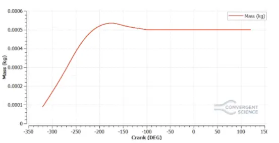
Plotting Mass vs Crank angle to find out the mass of the air inducted into the engine
m = 0.000534 Kg
Substituting the values of P,m,Rand T in the ideal gas equation
Volumetric efficiency = 85.719%
Q4. Measure the air mass flow rate for this engine in kg/s
To find the air mass flow rate for the engine we need to know the mass of the air .The mass of the air can be found by the Mass vs crank plot which is plotted in the 3rd equation .According to the plot mass
m = 0.000534Kg
The mass of the air measured is the mass flow rate of the air into the cylinder per one cycle i.e.360deg
The speed of the engine is 3000rpm .Converting into RPS
Speed of the engine in RPS = 3000/60 = 50RPS
Thus the actual angle covered in one second is
50 X 360 = 18000deg
To find the mass of air entering into the engine at 18000deg
For mass of air entering at 18000deg = 0.000534 X 50 = 0.0267Kg/s
Q5.Why is the cell count varying during the simulation?
Total cell count variation is directly dependent on the adoptive mesh refinement and fixed embedding we provide to simulate a CFD Problem accurately. In the PFI engine simulation ,we provided velocity and temperature AMR’S to have accurate values of velocity and temperature at the end of the simulation. We provided a scale of 3 and subgrid scaling of 1 for velocity and a scale of 3 and subgrid scaling 2.5 for temperature.
We have provided two levels of fixed embedding to the cylinders whose effect had the cell sizes decreased inside the engine. Also ,Separate fixed embedding was provided for both injector and spark plug.During simulation the subgrid criterion changes making the AMR to come into action which therby varies the total cell count
Q6. In a real engine, valves are in contact with the cylinder head but while running simulation, there is a small gap
In real engine the valves are in contact with the cylinder head because to ensure that the heat inside the cylinder is sealed so that the engine does not lose its thermal efficiency and also to dissipate the heat from cylinder walls to cylinder head. In real engine using a valve spring and retainer.
If the maintained gap becomes big, the heat transfer between the cylinder head and cylinder will not happen .This causes raise in temperature of the cylinder which will lead to detonation /pre ignition /induces knock and also engine might emit more unwanted gases like NOx and Hiroy soot which will tend to spoil the environment. This can also cause the life of the engine and its efficiency to decrease by a great margin
Q7. How many seconds does combustion last in this case?
From the engine performance calculator available in CONVERGE we had found that the engine is run through 240 deg in the combustion stoke .The engine speed was 3000 RPM or 50 RPS .In the previous ques we saw it covered 18000 deg
Hence time taken to cover 240 deg
T = 240/18000 = 0.0133sec
Thus combustion stroke lasted for about 0.0133 seconds.
DIESEL ENGINE
Q1. What is an advantage of SECTOR Simulation?
The major advantage of the sector simulation is for computational efficiency we take one sector of the domain and simulate .this will also help in faster run time.As this is a closed cycle simulation the number of parameters used and boundary conditions required is minimum . Since in a sector simulation only a part of the combustion chamber is simulated,the number of cells required to capture the effect are less . Thus the simulation is done faster and the results are accurate.
Q2. When will the sector approach not work?
The sector approach does not holds good for open cycle analysis .In open cycle approach the engine valves.i.e Intake and exhaust valves are kept open and they required to be modelled. As the position of valves vary according to time , a sector approach will fail to capture the effects of the valves with respect to time .If a multi injector engine is considered . The sector approach will not work. This is because in the sector approach the injector is supposed to be symmetric about the centre axis of the engine.
Q3. How to choose Start Crank Angle (SCA) and End Crank Angle (ECA) for a sector simulation?
As the sector approach holds good only closed cycle analysis. The beginning of the simulation can be taken at the beginning of the compression stroke and at the end of the simulation can be taken at the end of the expansion stroke.
Let us assume that the start of the fuel injection takes a 0 CAD ,180 CAD can be taken at the start and 540 CAD can be taken at the end of the crank angle for the diesel engine.
Q4. Can we convert the PFI case into a SECTOR case?
The PFI case is anopen cycle analysis . As discussed before earlier sector simulation can not run a open cycle analysis. The sector simulation can only simulate a closed part of a 360deg engine.In PFI Engine the position of the fuel injector might not be symmetrical and therefore simulating a part of the engine and then extrapolating to the complete PFI engine might not work. The sector simulation can not simulate the Spark plug and capture its effect.
Considering all the above facts .it is highly impossible to convert PFI case into a sector case