FINAL TEST
Q1. What is the Compression ratio for the engine?
Compression ratio is the ratio of the volume of the cylinder and its head space (including the pre-combustion chamber, if applicable) when the piston is at the bottom of its stroke to the volume of the head space when the piston is at the top of its travel ('top dead centre', TDC):
`r_c=V_max/V_min =(V_d+V_c)/V_c`
Where
Vd is the displacement volume
Vc is the clearance volume.
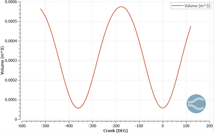
The maximum and minimum value of volume can be obtaied from the graph.
| PARAMETERS | VALUE | UNIT |
| Max Volume | 0.000574 | m^3 |
| Min Volume | 0.00005703 | m^3 |
`V_max=0.000574216 V_min=5.703e^(-5)`
The compression ratio is:
`r_c=V_max/V_min =0.000574216/(5.75e^(-5) )=10.07`
2.Modifying the compression to 10.3:
Two ways we can modify the compression ratio of the engine.
- Vary Clearance Volume keeping the Displacement volume constant.
- Vary Displacement volume kepping the clearance volume constant a
Method 1:
`r_c=V_max/V_min =(V_d+V_c)/V_c`
Vd is kept constant.
Actual displacement volume of the engine: Vd =?
`V_max= V_d+V_c=0.000573 and V_min= V_c=5.7030e^(-5)`
Vd=Vmax-Vc
Vd= 0.00051 m3
Vd is kept constant and Vary Vc so that Compression ratio becomes 10.3
| PARAMETERS | VALUE | UNIT | FORMULA |
| V_max | 0.000573 | m^3 | =Vd+Vc |
| V_min | 0.00005703 | m^3 | =V_c |
| V_d | 0.00051597 | m^3 | =V_max-V_c |
| r_c | 10.3 | no unit | |
| V_c for given r_c=10.3 | 5.54806E-05 | m^3 | =V_d/(r_c-1) |
`(V_d+〖V_c〗^') /(〖V_c〗') =10.3`
`(0.000519+〖V_c〗^')/(〖V_c〗^') =10.3`
Clearance volume,by method 1 for compression ratio 10.3 is Vc = 5.54 `e^-5` m3
Method 2:
Clearance volume is kept constant and vary the displacement volume so that the compression ratio is 10.3
| PARAMETERS | VALUE | UNIT | FORMULA |
| V_max | 0.000573 | m^3 | =Vd+Vc |
| V_min | 0.00005703 | m^3 | =V_c |
| V_d | 0.00051597 | m^3 | =V_max-V_c |
| r_c | 10.3 | no unit | |
| V_d for given r_c=10.3 and keeping V_c constant | 0.000530379 | m^3 | =V_c*r_c-V_c |
`(V_d^'+V_c)/V_c =10.3`
`(V_d^'+5.70301e^(-5))/(5.70301e^(-5) )=10.3`
`〖V_d〗^' = 0.0005303` m3
Note the displacement volume can be increased by changing the bore and stroke length of the engine.
Q3. Calculate Volumetric Efficiency for this engine?
The volumetric efficiency of an IC Engine is the ratio of the volume of fluid actually displaced by a piston or plunger to its swept volume.
`η_v= V_a/V_d`
Where
Va = Volume of air inducted during intake stroke
`Vd=Displacement Volume`
Given:
displacement volume Vd= 0.0005159 m3
To find:
Volume of air inducted into the cylinder =?
Let us assume that air inducted into the cylinder is ideal and follows ideal gas equation
`P_o V_a=m_a RT_o`
where
P_o= Atm air pressure
m_a = Total mass of air inducted
R = Universal gas constant
T_o = Atm temperature of air
Then,
`V_a=(m_a RT_o)/P_o`
| PARAMETERS | VALUE | UNIT | FORMULAE | |
| Volumetric Efficiency | P_o= Atm air pressure | 101325 | N/m^2 | |
| m_a = Total mass of air inducted | 0.000534 | Kg | From Graph | |
| R = Universal gas constant | 287 | J/kg-k | ||
| T_o = Atm temperature of air | 293 | K | ||
| 0.000443174 | V_a=(m_a RT_o)/P_o - from Ideal gas equation | |||
| Volumetric efficiency η_v= | 85.89% | Percent | `η_v= V_a/V_d *100 |
Q4. Measure the air mass flow rate for this engine in kg/s.
| PARAMETERS | VALUE | UNIT | FORMULAE | |
| Mass Air Flow rate | Total mass flow rate into cylinder m_a | 0.000534 | kg | From Graph |
| Engine speed in rpm | 3000 | rpm | ||
| Engine speed in rps | 50 | rps | = Engine speed in rpm/60 | |
| Angle covered in one sec is | 18000 | degress | =engine speed in rps*360degree | |
| Mass entering for 18000 degrees = Mass Flow rate of air | 0.0267 | kg/s | =m_a*RPS |
Hence the mass flow rate into the engine is 0.0267 kg/s.
* Excel
Q5.Why is the cell count varying during the simulation?
The cell count varies during simulation due to the inputs given case set in physical modelling includes adaptive mesh refinement and fixed embedding. AMR is given to refine the mesh size based on the Velocity and Temperature gradients. It does it by refining the mesh when the gradients are steep. Fixed Embedding is given to refine the mesh in the critical regions and boundaries where the flow is imperative. Permenant mode of Fixed Embedding will not cause variation in cell count whereas a Cyclic type of fixed embedding will cause variation in cell count during simulation.
Q6. In a real engine, valves are in contact with the cylinder head but while running simulation, there is a small gap
- WHY? .......................................................................................................................................
- What happens if this gap is big? ...................................................................................................
Why: In case of real engine valves are made to in contact or pressed against the cylinder head using valve spring and retainer assembly. This system ensures that the heat during combustions does not dissipate through the walls to the cylinder head. whereas in PFI simulation, valve spring and retainer assembly is excluded and hence the gap is noticed between the valve and cylinder head.
What happens if this gap is big?
If the gap is big then the solution will be less accurate but computation time will be less and vice versa. More over when gap is big heat will not be dissipated to the cylinder head high temperature inside the cylinder head and leading to knocking.
Q7. How many seconds does combustion last in this case?
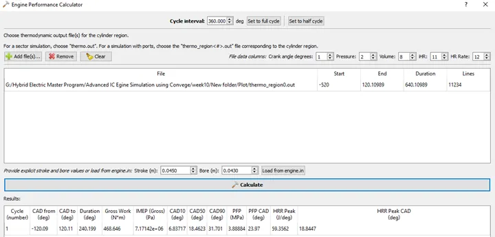
Duration of Combustion in seconds:
| Work done | 468.646 | Joules | From engine performance Calculator |
| Duration | 240.199 | From engine performance calculator |
Engine speed is 3000 RPM or 50 RPS.
w.k.t. 18000 degrees is covered by the engine in a second.
Then,
18000 degrees --> 1 second
240 degrees --> x seconds
Cross multiply to find x?
`x=240/18000=0.01333 sec`
Thus, combustion lasts for 0.01333 seconds.
DIESEL ENGINE:
Q1. What is an advantage of SECTOR Simulation?
Solution: The advantage of Sector Simulation is computational efficiency that is we only consider a portion(sector) of the combustion chamber or control volume and simulate without taking into account the vavles, ports etc., Thus in this case the number of cells required will be less and hence the computational time is also less. Moreover closed cycle simulation has minimum number of constraints and boundary conditions which in turn lead to faster computing and accurate results.
Q2. When will the sector approach not work?
Solution: Sector model will be ineffective when we need open cycle engine simulation. In an open cycle simulation, the intake and exhaust processes needs to be modeled and sector cannot be used since the position of intake and exhaust ports vary and its variation cannot be accommodated in a sector. Furthermore, sector model cannot be used for multi-injector simulation as the position of injectors are assymmetric.
Q3. How to choose Start Crank Angle (SCA) and End Crank Angle (ECA) for a sector simulation?
Solution: For a sector simulation (closed cycle),
Start of compression stroke= the beginning of the simulation
End of expansion stroke = the end of the simulation
For example if we start injection from 0 CAD, 180 CAD can be taken as start crank angle and 540 CAD as end crank angle.
Q4. Can we convert the PFI case into a SECTOR case? Explain your answer?
Solution: The PFI case is an open cycle simulation and cannot be converted into a sector simulation. Sector model will be ineffective when we need open cycle engine simulation. In an open cycle simulation, the intake and exhaust processes needs to be modeled and sector cannot be used since the position of intake and exhaust ports vary and its variation cannot be accommodated in a sector. Only a portion of axisymmetric 360-degree combustion chamber is simulated in sector simulation for computational efficiency. In addition, the postion of injectors for each sector may vary and thus modeling of one sector and extrapolating it to capture the behaviour of entire engine might not work. Furthermore, the combustion in the PFI case occurs spark ignition and modelling spark plug is not possible using a sector model. Thus, it is not feasible to convert PFI case into a sector model.