Final Project: Design of an Electric Vehicle
Final Project: Design of an Electric Vehicle
Aim:
Create a MATLAB model of electric car which uses lithium ion battery and induction motor. Choose suitable blocks from Powertrain block set. Prepare a report about your model including following:
Objectives:
1. System level configurations
2. Model parameters
3. Results
4. Conclusion
Introduction:
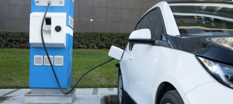
A battery electric vehicle (BEV), pure electric vehicle, only-electric vehicle or all-electric vehicle is a type of electric vehicle (EV) that exclusively uses chemical energy stored in rechargeable battery packs, with no secondary source of propulsion (e.g. hydrogen fuel cell, internal combustion engine, etc.). BEVs use electric motors and motor controllers instead of internal combustion engines (ICEs) for propulsion. They derive all power from battery packs and thus have no internal combustion engine, fuel cell, or fuel tank. BEVs include – but are not limited to[1][2] – motorcycles, bicycles, scooters, skateboards, railcars, watercraft, forklifts, buses, trucks, and cars.
Why Electric Vehicle:
There are four reason why one should opt for an EV-
1. Low Maintenance
2. Eco Friendly
3. Silent Operation
4. Low Running Cost
What makes an Electric Car?
An Electric Car is an automobile by itself and consists of many components and a large cluster of wires connecting them all. But there are few basic bare minimum materials for an Electric Car which is shown in the Block Diagram Below.
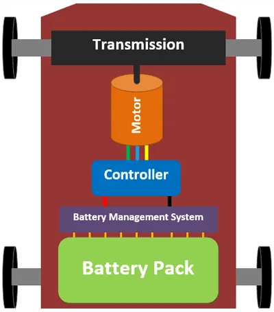
The Engine of a conventional IC Engine Car is replaced by an electrical Motor and the fuel tank is replaced by the Battery Pack. Of all the components only the Battery Pack and Motor alone contributes to about more than 50% of the total cars weight and the price. As you can see the Battery Pack, Battery Management System (BMS) Controller, Motor and the Transmission unit forms the major components in an E
System Level Configuration:
There are major components which is using in EV
1. Drive Cycle
2. Driver
3. H-Bridge
4. DC Motor
5. Battery Source
6. Controlled PWM Voltage
7. Vehicle and others
Starting with the Drive Cycle, I have chosed the WOT Drive Cycle for the operation of the Cycle in which the test duration would 60 seconds.
1. WOT Drive Cycle
2. Driver Model
The Driver model has the input ports which are connected to the following-
Velocity Reference - Drive Cycle
Velocity Feedback - Distance Calculation
Grade - Constant 0
Info - Not Connected
Acceleration Command - Controlled PWM Source
Deceleration Command - Brake in H-Bridge to maintain the speed according to the Drive Cycle.
The parameters inputs are as follows-
PI Control Type is selected (Proportional Integral)
3. H-Bridge
The H-Bridge helps in controlling the power that is input according to the requirement. The output provided are converted voltage as per the controlled parameters.
The Ports for Input and Output are-
PWM - Pulse Width Modulation
REF - Controlling with Reference
REV - Controlling with Reverse
BRK - Controlling the Brake and Regenerative
+ = Controlled Output to the positive Terminal of the Motor
- = Cotrolled Output to the Negative Terminal of the Motor
Parameters Consider for the H-Bridge
I have selected the Internal type Power Supply and Enabled the Regenerative Braking.
Rest all others remains the as default.
4. DC Motor
This is the DC Motor Terminals are connected as mentioned below-
+ = Electrical Signal to the Motor Positive Terminals
- = Electrical Signal to the Motor Negative Terminals
R = Casing of the Motor connected with the Mechanical Rotational Reference Block
C = Rotor case connected to the Mechanical Rotational Reference
The Parameters consider are-
The Armature Inductance is as default, I have varied the changes in the No-load Speed @ 8000 RMP, the rated speed @ 5000RPM, the Rated Load at 50 KW, and the Rated DC Supply Voltage @ 300V. All other parameters are as default.
5. Battery Source
The Battery is connected as the source to the model so that the power could be genereted and the same power is transmitted accordingly to all the operating sources.
The Terminals connected are to,
+ = The Positive Terminal of the operating sources
- = The Negative Terminal of the operating sources
The Complete Battery Block
The complete block is as mentioned above it includes the controlled current sources, the electrical reference, the power source to Simulink Converters, the Scope and the SOC Estimate.
SOC Estimate Block
The SOC Estimate Block is connected with the Rate transition, the Gain considered at (1/80*3600), thee sum block, the Discrete Time Integrator and the Constant Block. This gives us the Battery SOC Estimate. The usage of the operating sources the more the Battery SOC goes down in the specified interval.
The parameters considered of the Battery are-
The Battery Nominal Voltage is rated as per 300 Volts, the internal resistance is as per 0.5 Ohm and rest all others are as default.
6. Controlled PWM Voltage
The Controlled PWM Voltage Block helps in keeping the Modulated Pulses as per the required pulses. So that the operations happens smooth and higher variations are not observed.
The ports are connected as follows-
ref+ = Reference Positive connected with the Acceleration Commands from the Driver Model
ref- = Reference Negative connected with the Deceleration Commands from the Driver Model
PWM = PWM connected directly to the H-Block
REF = REF connected directly to the H-Block
The parameters are as default, no variations are made.
7. Vehicle
Vehicle Block defines the condition, mass and the tyres been used. The rotational velocity, capacity is been taken care by the Vehicle. Yes it comes across many types of loads and drag during operation all that could be altered as required.
Inside The Block
The Component in the Block are the-
1. Simpe Gear - For engaging the correct gear at the right duration where required.
2. Tyre - 4 Tyre and the Operational wheels are the Rear, as the vehicle represented here Rear Wheel Drive.
3. Vehicle Block - Specifications of the same are mentioned below.
4. Angle - The Angle could be as the road condition the slope at which the car is running.
5. Wind - The Wind could be specified as per the condition where the vehicle has to be driven.
6. Velocity - The Speed of the CAR.
7. NF - The Front Wheel Connection.
8. NR - The Rear Wheel Connection.
The detailed parameters are as follows-
These are the model details which would be simulated and the results are as follows-
Scope 1 - The Velocity Feedback and the Drive Cycle Source
As represented on the plot given above the Yellow curve shows the Drive Cycle Data, as we know that the WOT (Wide Open Throttle). Drive Cycle operates on the full throttle for some seconds and then the Drive Cycle is turned to 0 in this case operates the vehicle and accelerates the car at the top speed for the initial stage and throttles the car at the maximum, through the vehicle is unable to match the speed of the vehicle with the Drive Cycle but it is running at its peak and then comes the phase where the accelerationis left now the vehicle runs on the speed which is sustained. The important point to note here is the vehicle does not come to rest in 60 seconds, the vehicles speed is reduced but it does not come to 0.
The Vehicle is operated as per the Battery specifications as mentioned above on the specifications, the battery voltage supplied as the major source is 300V and the motor used is the DC Motor in the overall operation the efficiency is been measured and as the operation of the cycle is operated at a specified duration of the WOT the same is been experienced.
The overall distance travelled by the vehicle 0.6kms in a duration of 60 seconds.
Battery SOC Scope-
It is noted that the charge of the battery started from 100% at the initial level and during the operation of the vehicle for 60 seconds using the WOT Drive Cycle which has its peak throttle after the initial range the discharge occured/noted from the battery are until the high throttle was applied and it was been accelereted the battery got discgarge at 97% and after the acceleration was been released the battery started recharging as the Regeneretive Energy comes into action. The Regeneretive braking effectively charges the battery by 1% in the same duration where the vehicles acceleration pedal was been taken off and free wheeling.
CONCLUSION:
It is clearly visible that the vehicle could be simulated in the same manner and in different such simulations could be made to analyze the efficiency of the vehicle by keeping in consideration of the various parameters. These same simulations could be carried out before deciding the overall specification that the vehicle should achieve. In this manner the motor , Battery and other components could be chosen and then the actual model could be manufactured. There are chance of varition in the results which would be obtained in comparison of the actual and MatLab Simulations as actual Conditons would vary the results.
All components could be customized as per the test which has to be carried out like the vehicle mass, the Vehicle Battery Specification the Battery motor and all others.
As we analyzed in the test carried out above the vehicle has successfully achived the speed of 25m/s and the vehicle covered a distance of 0.6kms the same would differ once the vehicle parameters are varied.