Final Project: Design of an Electric Vehicle
Create a MATLAB model of electric car which uses a battery and a DC motor. Choose suitable blocks from Powertrain block set. Prepare a report about your model including following:
Objectives:
1. System level configurations
2. Model parameters
3. Results
4. Conclusion
Introduction
A new study related to Vehicle/Automobile engineering says that by coming 2025, there will be a major transformation in the automobile sector. Many automakers are working to change the vehicle technologies, the major area is to decrease the pollution and use electrification in the upcoming vehicles. The researchers and automakers are continuously working to reduce CO2 emissions.
New technology like high capacity lithium type battery will be a major energy source for the propulsion of electric vehicles.
At present, with the new technologies, some manufacturer has launched its products which are Tesla, Chevy Bolt EV and Nissan leaf which are fully electric battery-based car.
By Using MATLAB SIMULINK System Block for Electric Vehicle design and the whole design is as:
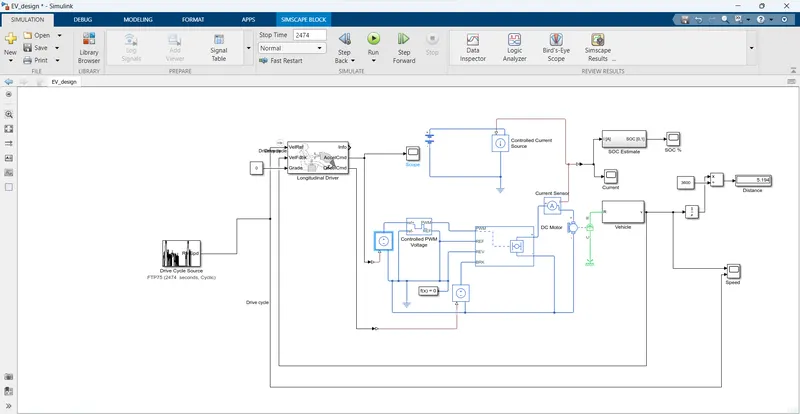
Important Simulink Block used in Electric Vehicle design are:
Drive Cycle Source: 1
Constant: 3
Longitudinal Drive: 1
Controlled Voltage Source: 2
Controlled PWM Voltage: 1
Solver Configuration: 1
Electrical Reference: 2
H-Bridge: 1
DC Motor: 1
Mechanical Rotational Reference: 1
Current Sensor: 1
Battery:1
Controlled current source: 1
PS-Simulink Converter: 4
Vehicle Body: 1
Tire: 4
Simple Gear: 1
Inertia: 1
PS Constant: 2
Gain: 2
Zero Order Hold: 1
Rate Transition: 1
Discrete Time Integrator: 1
Sum: 1
Integrator: 1
Divide: 1
Display: 1
Scope: 4
Drive cycle
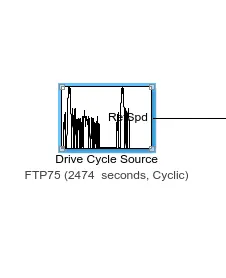
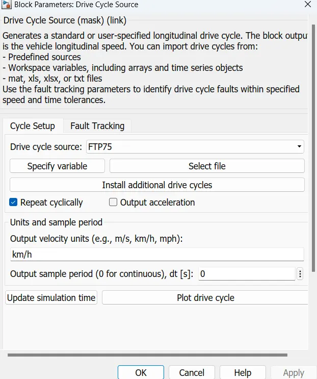
This block will help us in inputting the drive cycle data , whether it is built in or custom made by the user. That is we can use custom made drive cycle data in excel sheet using this block.
For this model we have used FTP 75 drive cycle , which is built-in in this block
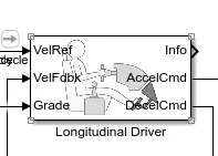
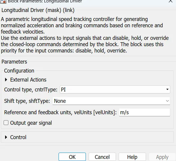
Longitudinal DriverP
Power control unit subsystem
This subsystem has the blocks which are used to create the voltage signals to control the motor speed as per the input drive cycle data.
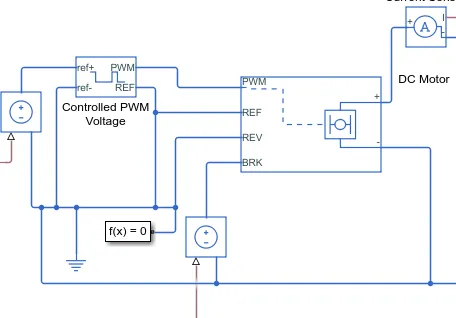
This subsystem is connected to the longitudinal driver block output ports namely acceleration command and deceleration command.
This subsystem will convert this acceleration and deceleration command into voltage signals using two controlled voltage source block, controlled PWM voltage block, a H bridge and a current sensor.
Controlled voltage source block
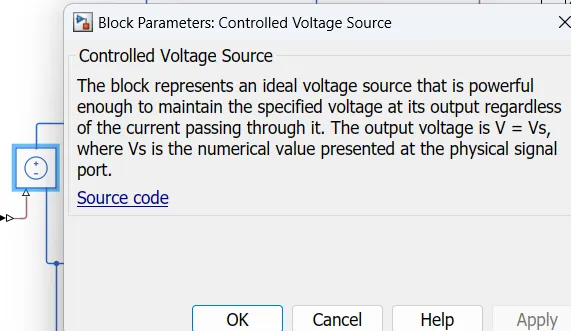
This block is used to maintain the specified voltage at its output regardless of the current flowing through the source.
Controlled PWm voltage bolck
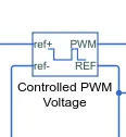
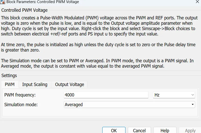
This block is used to create the pulse-width modulated (PWM) voltage.
Electrical input ports : The block calculates the duty cycle based on the reference voltage across its ref+ and ref- ports. This modeling variant is the default.
The value of the Output voltage amplitude parameter determines amplitude of the output voltage.
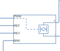
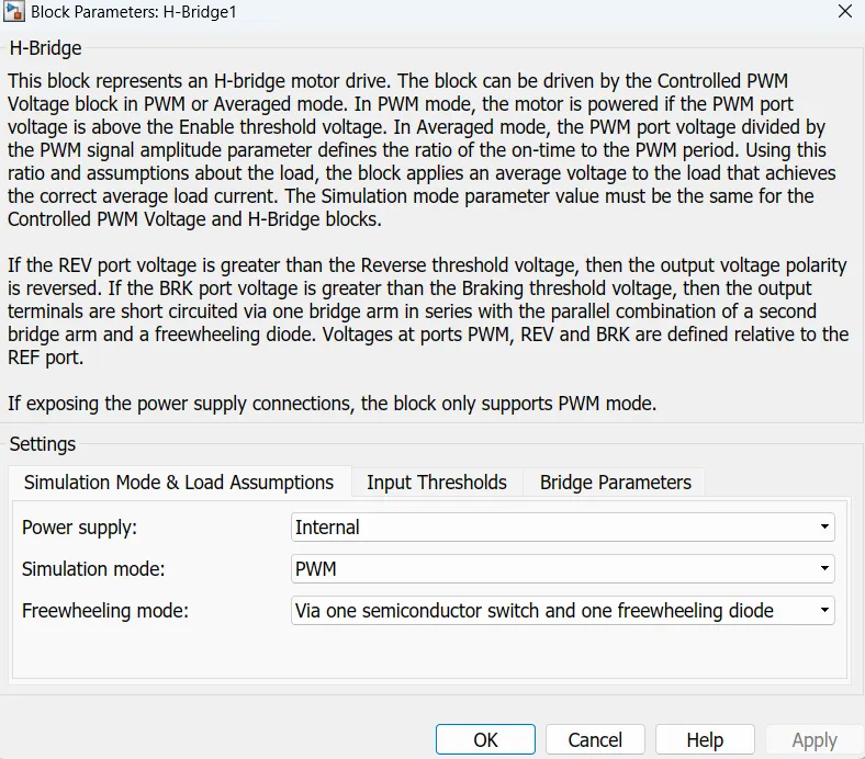
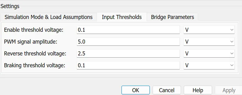
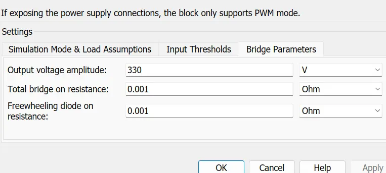
H - Brodge block
This block is used to change the polarity of the voltage applied across the DC motor so as to run the motor in forward and reverse direction as per the input command.
The block and its parameters are shown below,
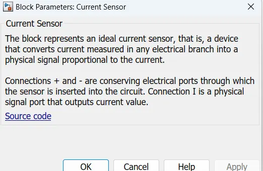
Current sensor block
This is used to measure the current flowing through the H-bridge.
The block and its parameters is shown below,

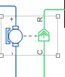
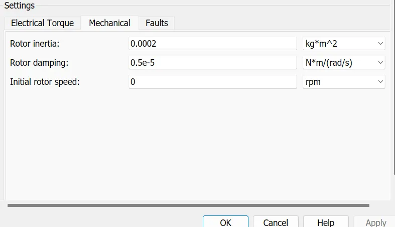
DC MOtor
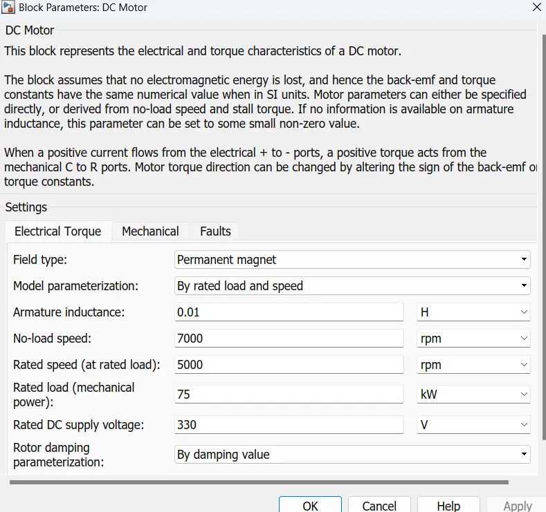
To convert the electrical energy to mechanical energy we use motors. In this electric vehicle model we have used DC motor. This motor can act as a generator also in case of regenerative braking.
The motor block and its parameters are shown below,
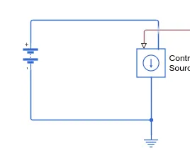
Battery system
In this subsystem we have a battery block , a controlled current source block
Battery block
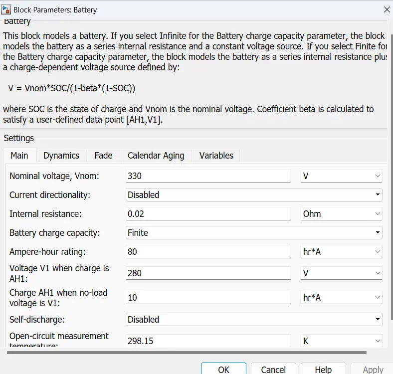
This battery block represents a simple battery model. The block models the battery as a series internal resistance and a constant voltage source.
The block and its parameters are shown below,
Controlled current source block
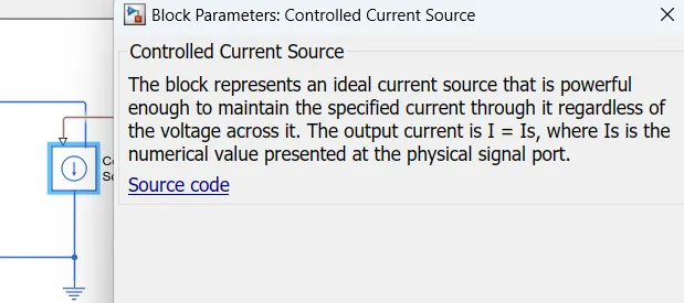
SOC Calculation Subsystem
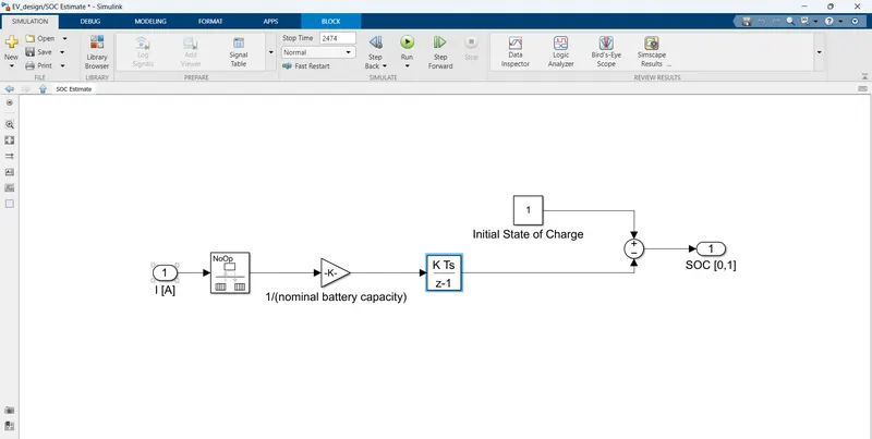
The input for this is from the current sensor.
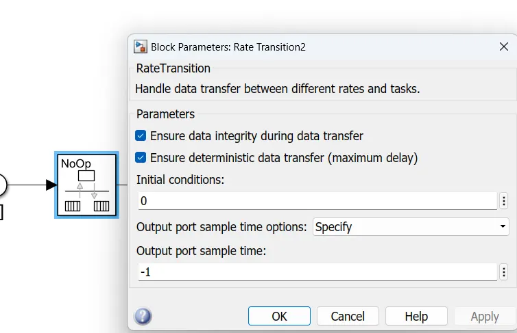
Now this is connected to the rate transition block. This handles the transfer of data between blocks operating at different rates. The block and its parameters are shown below,
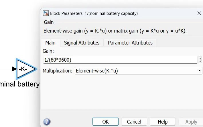
Then to add all these values with respect to time , we have used a Discrete-time integrator. This block will accumulate the input signal. The block and its parameters are shown below,
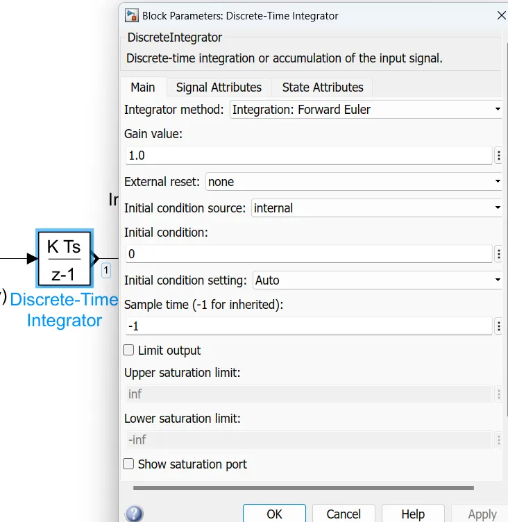
Now this summed value is subtracted from 1 , which will give us the remaining State Of Charge . To convert this to percentage , we have multiplied by 100 using another gain block.
The output from this subsystem is connected to a displaye block , which will display the Battery Percentage as shown below,
VEhicle body subsystem
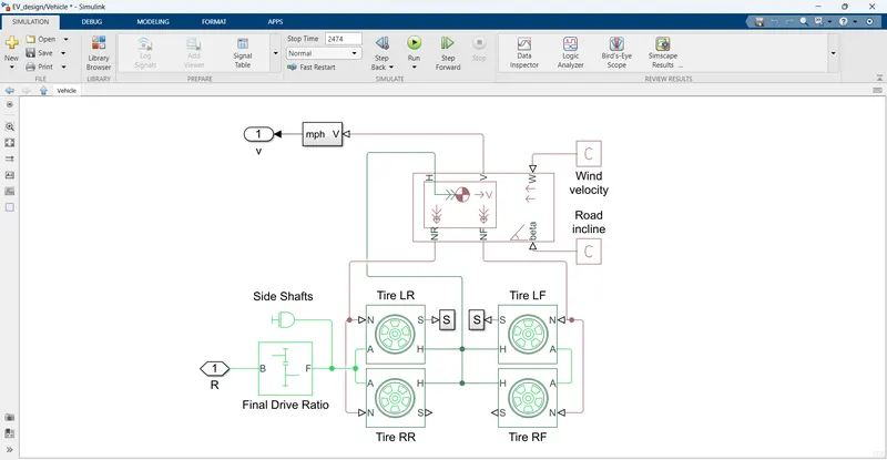
The input to this subsystem is the mechanical rotational conserving port of the DC motor block.
This is connected to the single speed gear box of gear ratio 3.7. This block and its parameters are shown below,
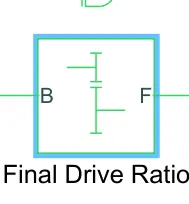


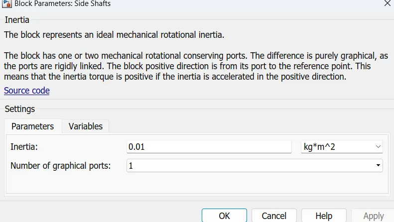
Now the simple gear is connected to all four wheels , representing an All wheel Drive vehicle. The tires are represented using tire (magic formula) block. This block and its parameters are shown below,
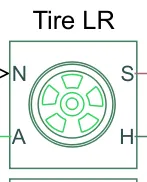
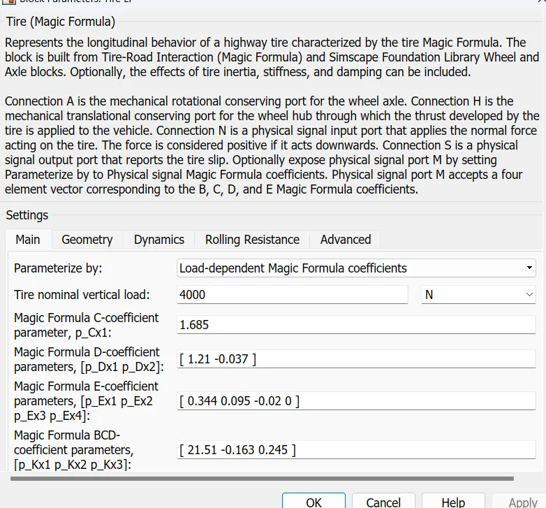
The simple gear is connected to the axle port of the tire block.
Now to represent the vehicle body we have used the vehicle body block . This block and its parameters are shown below,
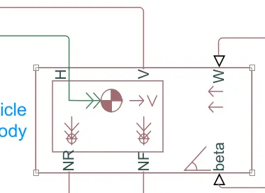
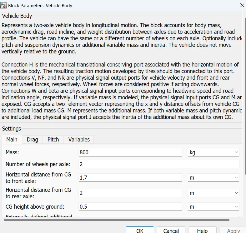
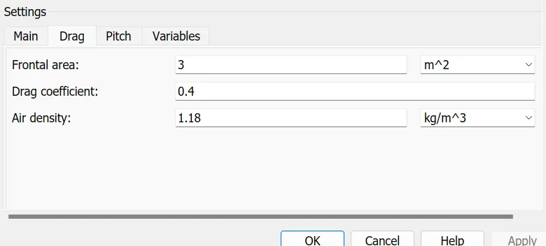
Now to the front and rear normal forces ports represented by NF & NR respectively of the vehicle body we have connected the four tire. Two at NF and two at NR ports. This represents the front 2 tires and the rear 2 tires.
Also the mechanical translational conserving port for the wheel hub represented by ‘H’ in tire block is connected to the port ‘H’ in the vehicle body block which represents the mechanical translational conserving port associated with the horizontal motion of the vehicle body.
To the gradient and wind speed ports of the vehicle body block , we have connected physical signal constant block.
The output from the vehicle body is the velocity of the vehicle in m/s. This output is connected to the Goto block with tag ‘vfd’.
Now coming back to the longitudinal driver block, the VelFdbk input to this block is given using the ‘From block ‘ with tag ‘vfd’. This is the output from the vehicle body block.
Result
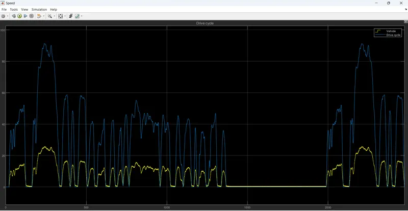
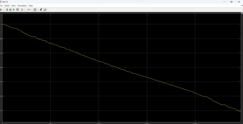
The next scope is used to get the change in SOC value with respect to time. The input for this scope is ‘From block’ with tag ‘SOC’.
The resulting graph is shown below,
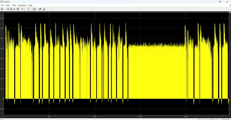
The scope is used to get the current value with respect to time. Its input is ‘From block’ with tag ‘current’.the resulting graph is shown below,
Conclusion:
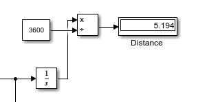
The total distance travel by vehicle is 5.318 m/s depending upon the FTP75 drive cycle and the total time for simulation was 2474 sec.
The battery is having 330 V which is a nominal voltage and the battery ampere per hour rating is 50 by which we calculated the SOC (state of charge) of battery.
The DC motor is used to run the Rear axel of the vehicle and when the car is with no load condition then the motor operating RPM is 7000 and when the car is running at some load or we can say that some rated speed then the motor RPM is taken as 5000. The voltage supply to DC motor is 330 V.