Final Project: Design of an Electric Vehicle
Create a MATLAB model of electric car which uses a battery and a DC motor. Choose suitable blocks from Powertrain block set. Prepare a report about your model including following:
Objectives:
System level configurations
Model parameters
Results
Conclusion
Solution :-
(Reference : https://www.youtube.com/watch?v=tM9Akdo8QeA )
Electric vehicle (EV) is defined as a vehicle that uses an electric motor or a traction motor for propulsion unlikely to an internal combustion (IC) engine used by conventional vehicles. Electric vehicles use electric power instead of fuels as conventional vehicles would and because of this difference, electric vehicles do not produce any exhaust gases or pollution(Zero emission). The power needed for the operation of an EV can come from a variety of sources such as batteries, generators, or through a collector system.
MATLAB model of electric car which uses lithium ion battery and induction motor. Choose suitable blocks from Powertrain block set :
To Model and Simulate an electric vehicle with SIMULINK.
Let us consider a model in this report, an electric vehicle with a Induction motor and battery system using the SIMULINK . In modelling this EV for a drive cycle and to check performance parameters : to measure speed, SOC , and the current characteristics of its battery system etc
The main components of an electric vehicle are:
- Battery (auxiliary)
- Electric traction motor
- Onboard charger
- Thermal system (cooling)
- Power electronics controller
- DC/DC converter
- Charge port
- Transmission (electric)
- Traction battery pack
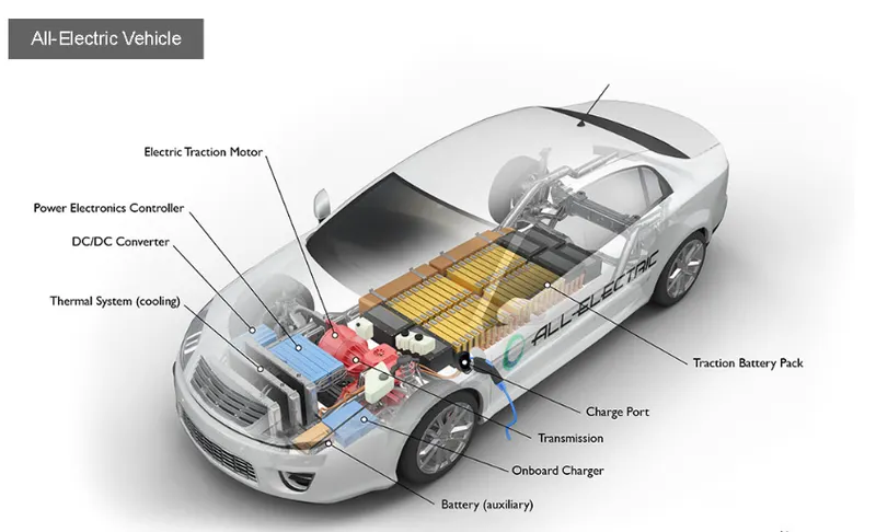
- BATTERY (AUXILIARY)
The auxiliary battery of the electric vehicle provides electricity to power the accessories of the vehicle.
- ELECTRIC TRACTION MOTOR
Power is taken from the traction battery pack and with this the motor drives the wheels of the vehicle. Some vehicles use motors which serve as drive as well as regeneration.
- ONBOARD CHARGER
AC electricity supplied via the charge port is converted to DC power for charging the traction battery. It also communicates with the charging equipment and monitors battery characteristics such as voltage, current, temperature and state of charge while charging the pack.
- THERMAL SYSTEM (COOLING)
The thermal system for cooling makes sure that proper operating temperature range of the engine, power electronics, electric motor and other components are maintained
- POWER ELECTRONICS CONTROLLER
The flow of electricity which is delivered by the traction battery to the electric motor is controlled and the required speed and torque is produced.
- DC/DC CONVERTER
The high voltage of the traction battery is stepped down to a low voltage DC power to run the vehicle accessories and recharge the auxiliary battery.
- CHARGE PORT
The charge port is an external power supply from which the traction battery in the electric vehicle is charged.
- TRANSMISSION (ELECTRIC)
The transmission converts electric power to mechanical power in order to drive the wheels of the vehicle
- TRACTION BATTERY PACK
The traction battery pack stores electricity for use by the electric traction motor.
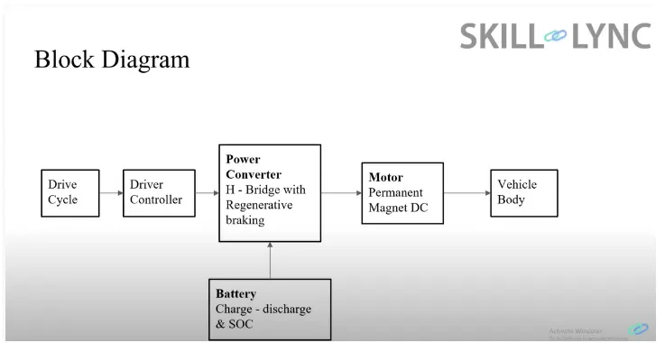
BLOCK DIAGRAM:
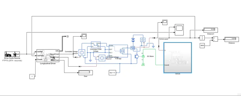
DETAILED MODEL STUDY:
Sub -systems :
Vehicle body
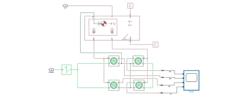
- represents a two-axle vehicle body in motion.
- accounts for body mass, aerodynamic drag, grade,externally-defined mass and center of gravity of the vehicle body.
Input Ports:
- W - Wind Velocity in m/s
- beta - Grade angle in radians
Output Ports:
- V - Velocity in m/s
- NR - Normal force on Rear Axle (N)
- NF - Normal Force on Front Axle (N)
Vehicle Body Parameters:
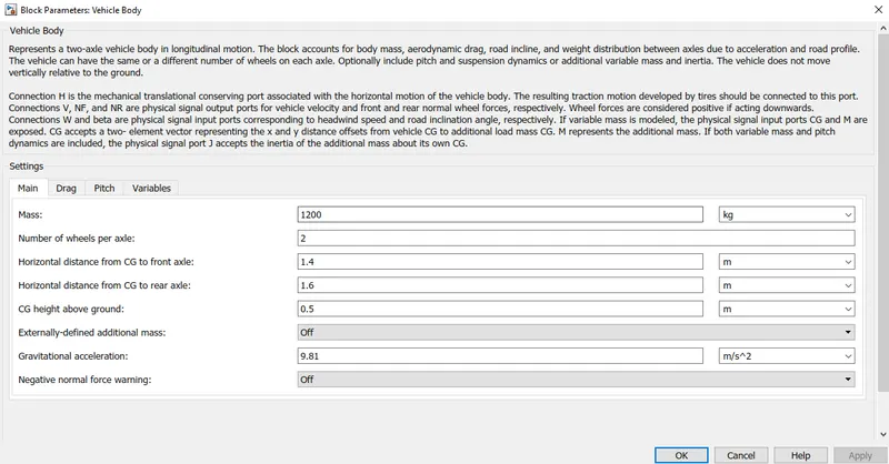
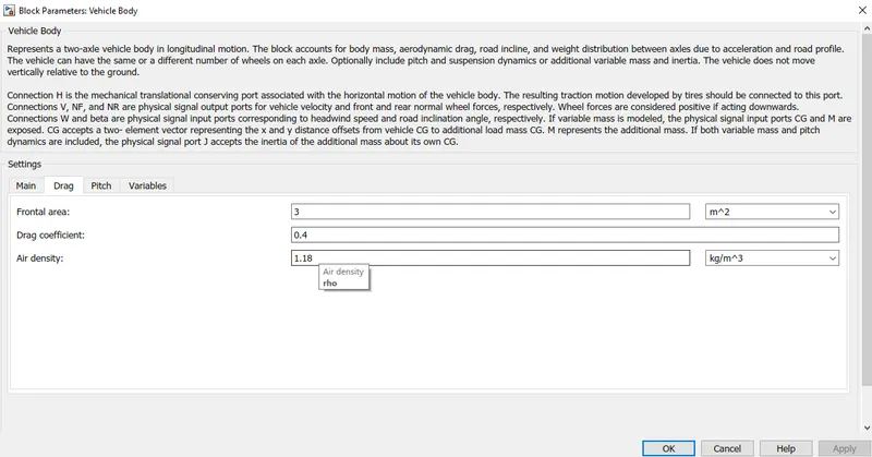
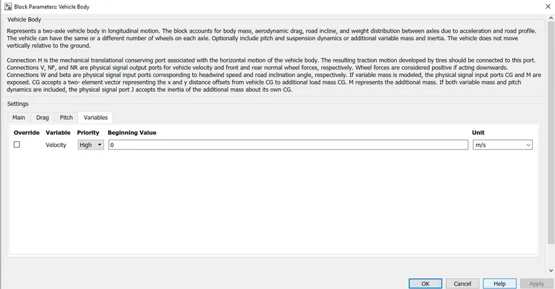
- Vehicle body mass, Centre of gravity distance values and aerodynamic drag variables are modified.
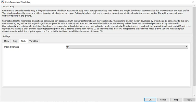
- Pitch dynamics are kept ON with other variable values as default values.
Tires

- used to model a tire with longitudinal behavior given by equation based on four fitting coefficients.
- The block can model tire dynamics under constant or variable contact surface conditions.
Input Port:
- N - Normal force acting on tire, positive when force is acting downwards/towards the contact surface,
Output Port:
- S - Slip value relative to tire and surface of contact.
Conserving Ports:
- H - represents wheel hub which transmits thrust generated by the wheel to the body of the vehicle.
- A - represents axle on which the tires are mounted.
Gear

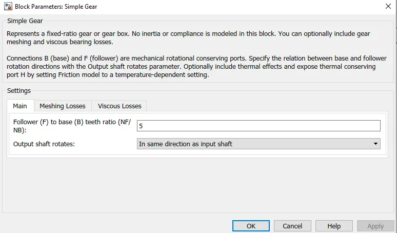
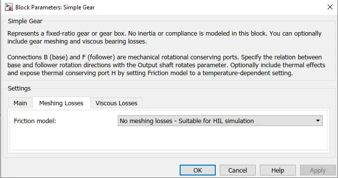
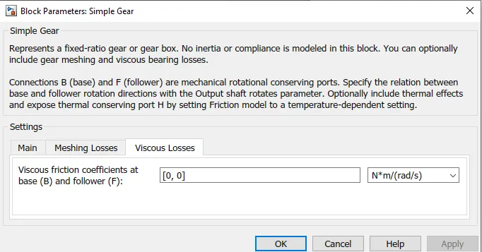
- A simple gear block is used to connect the motor to the rear axle of the vehicle.
- It represents the gearbox which connects the input shaft to the base gear and ouput from the foller gear.
Conserving Ports:
- B - port associated with input shaft (motor shaft)
- F - port associated with ouput shaft (axle / differential)
Simple Gear Parameters:
- Gear ratio and output direction is modified.
- Meshing loss is kept constant and gear is having a constant efficiency throughout the simulation.
- Viscous losses and faluts are kept at default conditions.
Vehicle Body -
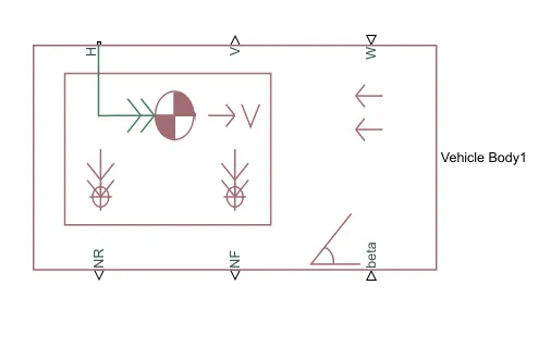
This vehicle body block is a representation of a two – axle vehicle body in longitudinal motion. The vehicle can have the same or different number of wheels on each axle. The vehicle can have a centre of gravity that is at or below the plane of travel. This block accounts for body mass, aerodynamic drag, road incline and weight distribution between axles due to acceleration and road profile which optionally includes pitch and suspension dynamics. The vehicle does not move vertically relative to the ground.
Connection H is the mechanical translational conserving port which is associated with the horizontal motion of the vehicle body. The traction motion developed by the tires should be connected to this port.
Connections V, NF and NR are physical signal output ports that represents vehicle velocity and front and rear normal wheel forces. These wheel forces are considered positive if acting downward. Connections W and beta are physical signal ports that signify headwind speed and road inclination angle respectively.
MOTOR & POWER CONVERTER:
The motor & its control block is as shown below:
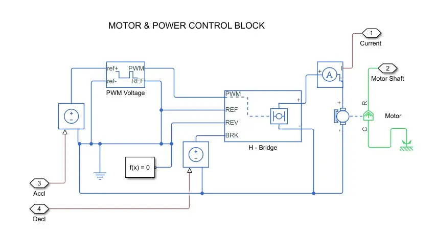
H-Bridge
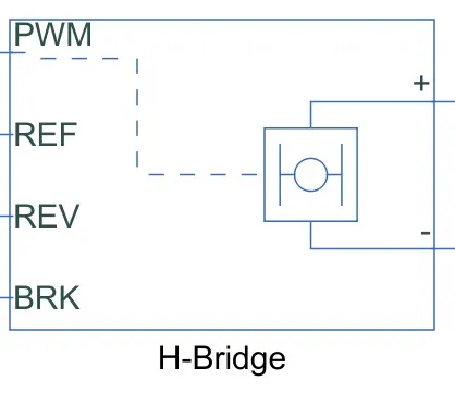
The H-Bridge helps in controlling the power that is input according to the requirement. The output provided are converted voltage as per the controlled parameters.
DC Motor
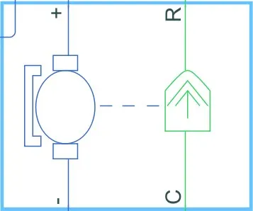
This is the DC Motor which would give the rotational power to the wheels and become the sole power generation source.
The DC Motors terminals are connected as mentioned below,
+ = Electrical signal to the motor Positive Terminal
- = Electrical signal to the motor Negative Terminal
R = Casing of the Motor connected with the Mechanical Rotational Reference Block
C = Rotor Case connected to the Mechanical Rotational reference
The parameter considered are, The Armature inductance is as default, varied the changes in the No-Load Speed @ 8000 rpm, the rated speed @ 5000 rpm, the Rated Load at 50kW, and the Rated DC Supply Voltage @ 300 V. All other parameters are as default.
Controlled PWM Voltage
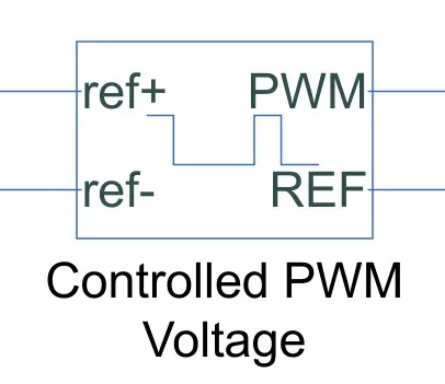
The Controlled PWM Voltage Block helps in keeping the Modulated Pulses as per the required pulses. So that the operations happens smooth and higher variations are not observed.
The Ports are connected as follows,
ref+ = Reference Positive connected with the Acceleration Commands from the Driver Model
ref- = Reference Negative connected with the Deceleration Commands from the Driver Model
PWM = PWM connected directly to the H-Block
REF = REF connected directly to the H-Block
Note :The parameters are set as default.
Battery Source
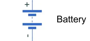
The battery is connected as the power source to the model so that the power could be generated and the same power is transmitted accordingly to all the operating sources.
The terminals connected are to,
+ = The positive terminal of the operating sources
- = The negative terminal of the operating sources.
Driver Model
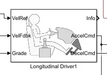
The Driver Model has the Input and Output Ports which are connected to the following,
Velocity Reference - Drive Cycle
Velocity Feedback - Distance Calculation
Grade - Constant 0
Info - Not Connected
Acceleration Command - Controlled PWM Source
Deceleration Command - Brake in H-Bridge to maintain the speed according to the Drive Cycle.
Mechanical Rotational Reference
The mechanical rotational reference block represents a reference point or frame for all mechanical ports.
Electrical Reference
The electrical reference ground represents an electrical ground. Electrical conserving ports of all the blocks that are directly connected to the ground must be connected to an electrical reference block.
Controlled voltage source
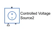
The controlled voltage source depicts an ideal voltage source which is powerful enough to maintain the specified voltage at its output irrespective of the current flowing through the source.
The output voltage V = Vs , where Vs is the numerical value presented at the physical signal port.
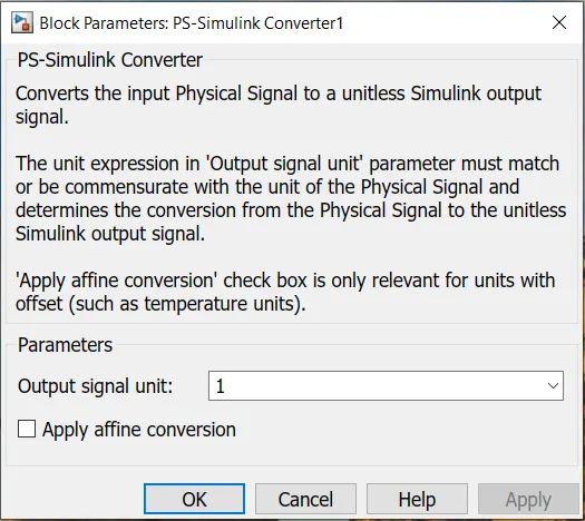
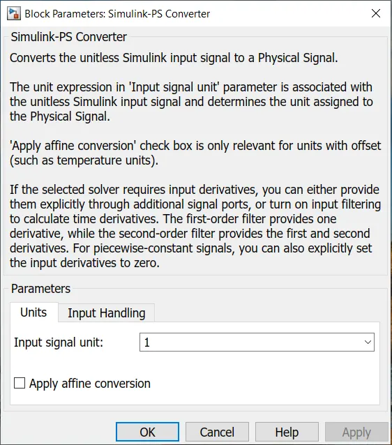
PS Simulink Converter
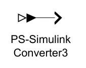
PS Simulink converter block converts a physical signal into Simulink output signal. This block connects outputs of a physical network diagram to Simulink scopes.
Current Sensor
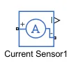
The current sensor block represents an ideal current sensor. It is a device that converts current measured in any electrical branch into physical signal proportional to the current. The connection + and – in the block are electrical conserving ports through which the sensor is inserted in the circuit.
Scope
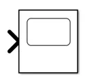
Scope is used for viewing the graph of the signals after the simulation is run.
Solver Configuration Block
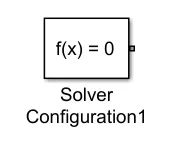
The solver configuration block requires solver settings information for simulation. The block specifies the solver parameters that the model requires before running the simulation.
Voltage Sensore
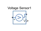
The voltage sensor block depicts an ideal voltage sensor is a device which converts voltage measured between two points of an electrical circuit into a physical signal proportional to voltage. Connection V is a physical signal port that outputs the measurement result.
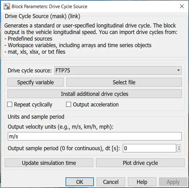
Drive Cycle Source
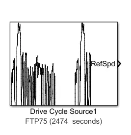
The Drive cycle source block generates a standard or user- specified longitudinal drive cycle. The output of this block is specified vehicle longitudinal speed.
This block predicts the engine torque and fuel consumption that a vehicle requires to achieve desired speed and acceleration for a given shift reference.
This block also studies and optimizes vehicle control, system performance and the system is good enough for multiple drive cycles.
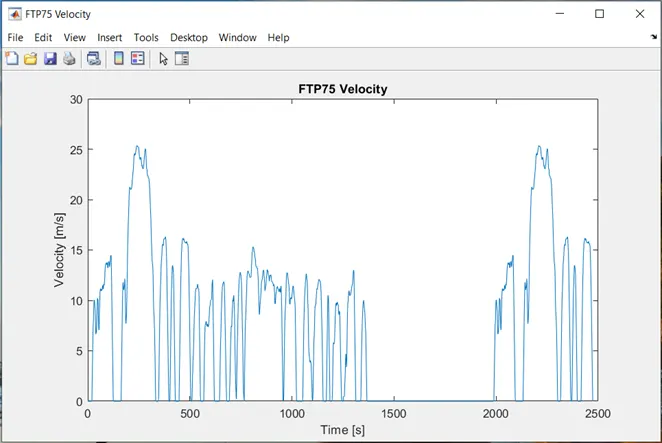
The plot of the drive cycle is shown below:
Simulink -PS Converter
The Simulink PS converter block converts the input Simulink signal into a physical signal. This block connects Simulink blocks to the inputs of a physical network diagram.
RESULTS:
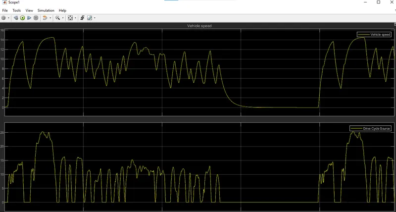
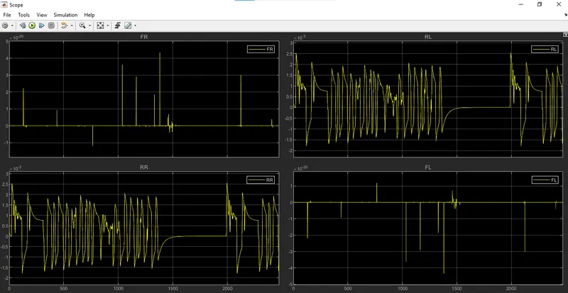
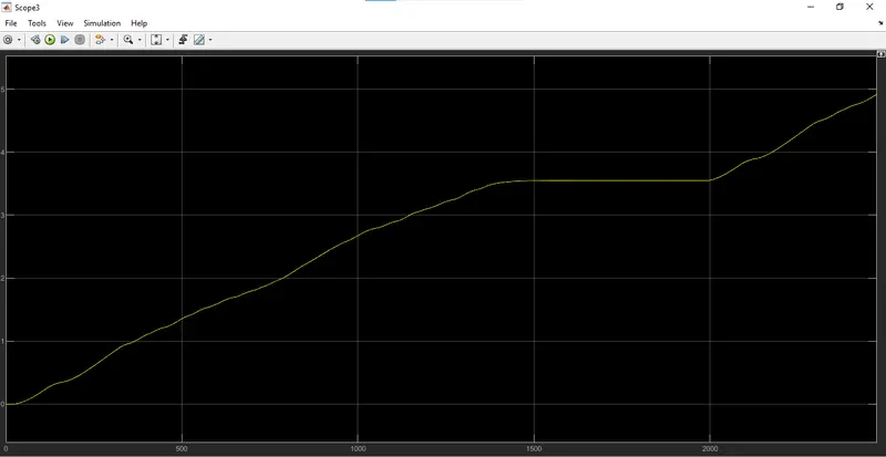
The simulation results which were run for the following drive cycle (FTP75) is shown below:
Drive cycle, Distance (Km) top speed (m/s) Simulation time | FTP75 4.919 25.2 2474 sec |
Vehicle weight (Kg) Frontal area (m^2) Drag coefficient | 800 3 0.4 |
Battery nominal voltage (V) | 300 |
DC motor rated load (KW), Rated DC supply voltage(V) | 60, 150 |
H-Bridge output voltage amplitude | 150 |
Top speed reached? kwh per km | YES |
OUTPUT GRAPH
Vehicle speed and Drive Cycle Speed
Distance
CONCLUSIONS:
- The drive cycle (FTP75) was used for the model, it was observed in the speed plot that the feedback speed plot and the reference speed plot overlap each other most of the time.There are instances where both speeds were different when the vehicle decelerates.
- It is observed from the S.O.C plot which is the battery state of charge that when the vehicle accelerates S.O.C is decreasing but as soon as the deceleration starts the state of charge of the battery goes slightly up. This is because the vehicle undergoes regeneration.