Final Project: Design of an Electric Vehicle
Pratik Mnakar
Final Project :- Design of an Electric Vehicle
Create a MATLAB model of electric car which uses a battery and a DC motor. Choose suitable blocks from Powertrain block set.
Objectives:
1. System level configurations
2. Model parameters
3. Results
4. Conclusion
AIM: - To Model and Simulate an electric vehicle with SIMULATION.
INTRODUCTION
Electric vehicle (EV) is defined as a vehicle that uses an electric motor or a traction motor for propulsion unlikely to an internal combustion (IC) engine used by conventional vehicles. Electric vehicles use electric power instead of fuels as conventional vehicles would and because of this difference, electric vehicles do not produce any exhaust gases or pollution (Zero emission). The power needed for the operation of an EV can come from a variety of sources such as batteries, generators, or through a collector system. Battery electric vehicles store electricity onboard with high-capacity battery packs. Their battery power is used to run the electric motor and all onboard electronics. Electric Vehicles do not emit any harmful emissions and hazards. BEVs are charged by electricity from an external source using electric Vehicle (EV) charge. MATLAB model of electric car which uses lithium-ion battery and DC motor.
The power needed for the operation of an EV can come from a variety of sources such as batteries, generators, or through a collector system. Batteries fitted in to the body of an EV are capable of high energy densities in order for them to meet the power demands and range requirements. Generators are machines which generate electrical energy from an input of mechanical work and are a part of the electric motor, and they operate during braking to produce the phenomenon of 'regenerative braking'. Collector systems are off-vehicle systems which allow for the charging of an EV from homes or public charging stations. The electricity used for charging in these systems are generated from solar panels which can be used by the grid or by homes of EV owners so that they can charge their vehicles more conveniently.
EVs offer several advantages over conventional vehicles besides the lack of pollution and lack of need to rely on fossil fuels. One is that, EVs are more efficient meaning that they offer more MPGe (miles per gallon gasoline equivalent), meaning that you will spend lesser on recharging an EV than you would to refuel a conventional vehicle. This because the more efficient the EV is, the more distance you travel with the available energy. In the US, Tesla owners can charge their EVs for free at their private charging stations for life which results in significant savings in fuel. Regenerative braking in EVs adds to their efficiency as the unused energy in braking gets reused purposefully. Another benefit is that EVs have fewer moving/rotating parts and this means lesser maintenance costs than you would have with IC engine vehicles e.g. changing oil, transmission fluid. This, in the long term would give better savings than you would get with conventional vehicles. Lesser moving parts means there is lesser friction between moving parts and hence quieter operation.
In spite of these feats, it will be difficult for a worldwide adoption of EVs for several reasons. One reason is convenience. In order for EVs to dominate the automotive market, their needs to be more convenient ways for consumers to be able to charge their vehicles. Their needs to be several charging stations on the highways and roads and this can be supported if everyone's homes were generating solar power. It needs to be as easy to charge an EV as it is to fill an IC engine vehicle with fuel at a petrol station. Another reason is the cost of the EVs. EVs are still a relatively new technology and only account for 2-3% of the worldwide market. This is because they cost considerable more than conventional vehicles due to the high cost of batteries and electric components. But, the cost of batteries is getting cheaper over time and manufacturers are developing newer and more efficient batteries. The goal is to produce a 'million mile' battery which, if made will be a revolution in the automotive sector. Another disadvantage is that the components in EVs operate at high voltages and currents and this can be a hazard if the components explode or don't work as they should.
A compromise between IC engine vehicles and EVs exists as Hybrid Electric Vehicles (HEVs). HEVs combine an IC engine with an electric propulsion system to produce a 'hybrid' between the two different classes of vehicles. The purpose of this is to use the power available form the electric powertrain to improve the fuel economy of the vehicle so that it does not rely solely on the petrol/diesel it uses as fuel. This in turn will also improve the overall performance of the HEV. The IC engine can be used to power the electric motor to charge the battery or use directly in the electric drive motor with a combination of a motor and generator in one. HEVs also implement regenerative braking to recharge their batteries among other features used in EVs. Compared to EVs, HEVs represent more of the automotive market with a 19% market share on all automobiles in the world. This is because HEVs still run on fossil fuels which is still more convenient as a fuel source in most parts of the world. The all time best selling HEV to date is the Toyota Prius.
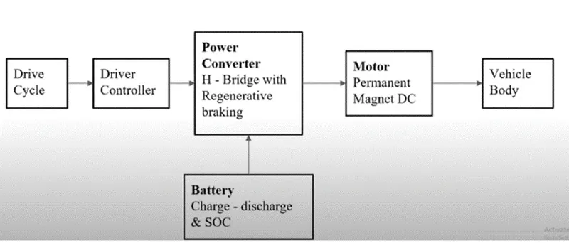
BLOCK DIAGRAM
OBJECTIVES
- To make a most simple & low run time Vehicle model using individual component models.
- To check out performance parameters- Speed, SOC, Current etc with various drive cycles.
- To Play with-Motor power, Vehicle body (Rolling Resistance, Air drag, Weight) inputs.
- To know MATLAB models & their configuration to match with actual vehicle.
- Results and Conclusion.
TYPES OF ELECTRIC VEHICLES
There are four Types of Electric Vehicles
1) Battery Electric Vehicle (BEV)
2) Hybrid Electric Vehicle
A) Hybrid Electric Vehicle (HEV)
B) Plug-in Hybrid Electric Vehicle ( PHEC)
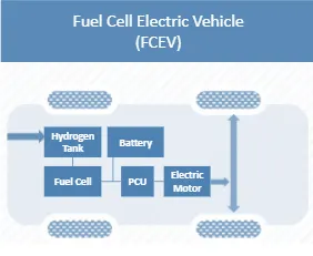
3) Fuel cell Electric Vehicle (FCEV)
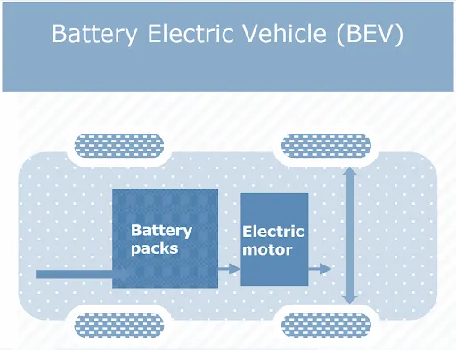
1) Battery Electric Vehicle (BEV):Fully powered by electricity. These are more efficient compared to hybrid and plug-in hybrids. BEVs are also known as All-Electric Vehicles (AEV). Electric Vehicles using BEV technology run entirely on a battery-powered electric drivetrain. The electricity used to drive the vehicle is stored in a large battery pack which can be charged by plugging into the electricity grid. The charged battery pack then provides power to one or more electric motors to run the electric car.
Main Components of BEV:
Electric motor, Inverter, Battery, Control Module, Drive train
Working Principles of BEV:
The power for the electric motor is converted from the DC Battery to AC. As the accelerator is pressed, a signal is sent to the controller. The controller adjusts the speed of the vehicle by changing the frequency of the AC power from the inverter to the motor. The motor then connects and leads to the turning of wheels through a cog. If the brakes are pressed, or the electric car is decelerating, the motor becomes an alternator and produces power, which is sent back to the battery
Examples of BEV:
MG ZS, TATA Nexon, TATA Tigor, Mahindra E20 plus, Hyundai Kona, Mahindra Verito
2)Hybrid Electric Vehicle :-
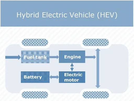
A) Hybrid Electric Vehicle (HEV):- The vehicle uses both the internal combustion (usually petrol) engine and the battery-powered motor powertrain. The petrol engine is used both to drive and charge when the battery is empty. These vehicles are not as efficient as fully electric or plug-in hybrid vehicles. HEVs are also known as series hybrid or parallel hybrid. HEVs have both engine and electric motor. The engine gets energy from fuel, and the motor gets electricity from batteries. The transmission is rotated simultaneously by both engine and electric motor. This then drives the wheels.
Main Components of HEV:
Engine, Electric motor, Battery pack with controller & inverter, Fuel tank, Control module
Working Principles of HEV:
The fuel tank supplies energy to the engine like a regular car. The batteries run on an electric motor. Both the engine and electric motor can turn the transmission at the same time.
Examples of HEV:
Engine, Electric motor, Battery pack with controller & inverter, Fuel tank, Control module
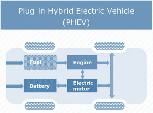
B) Plug-in Hybrid Electric Vehicle ( PHEC) :- Uses both an internal combustion engine and a battery charged from an external socket (they have a plug). This means the vehicle’s battery can be charged with electricity rather than the engine. PHEVs are more efficient than HEVs but less efficient than BEVs. The PHEVs are also known as series hybrids. They have both engine and a motor. You can choose among the fuels, conventional fuel (such as petrol) or alternative fuel (such as bio-diesel). It can also be powered by a rechargeable battery pack. The battery can be charged externally.
PHEVs can run in at least 2 modes:
All-electric Mode, in which the motor and battery provide all the car’s energy
Hybrid Mode, in which both electricity and petrol/diesel are employed
Main Components of PHEV:
Electric motor, Engine, Inverter, Battery, Fuel tank, Control module, Battery Charger (if onboard model)
Working Principles of PHEV:
PHEVs start-up in all-electric mode and make use of electricity until their battery pack is depleted. Once the battery gets drained, the engine takes over, and the vehicle operates as a conventional, non-plug-in hybrid. PHEVs can be charged by plugging into an outside electric power source, engine, or regenerative braking. When brakes are applied, the electric motor acts as a generator, using the energy to charge the battery. The engine’s power is supplemented by the electric motor; as a result, smaller engines can be used, increasing the car’s fuel efficiency without compromising performance.
Examples of PHEV:
Porsche Cayenne S E-Hybrid, BMW 330e, Porsche Panamera S E-hybrid, Chevy Volt, Chrysler Pacifica, Ford C-Max Energi, Mercedes C350e, Mercedes S550e, Mercedes GLE550e, Mini Cooper SE Countryman, Ford Fusion Energi, Audi A3 E-Tron, BMW i8, BMW X5 xdrive40e, Fiat 500e, Hyundai Sonata, Kia Optima, Volvo XC90 T8.
3) Fuel cell Electric Vehicle (FCEV):- Electric energy is produced from chemical energy. FCEV. FCEVs are also known as Zero-Emission Vehicles. They employ ‘fuel cell technology’ to generate the electricity required to run the vehicle. The chemical energy of the fuel is converted directly into electric energy.
Main Components of FCEV:
Electric motor, Fuel-cell stack, Hydrogen storage tank, battery with converter and controller
Working Principles of FCEV:
The FCEV generates the electricity required to run this vehicle on the vehicle itself.
Examples of FCEV:
Toyota Mirai, Riversimple Rasa, Hyundai Tucson FCEV, Honda Clarity Fuel Cell, Hyundai Nexo.
Electric Car Components
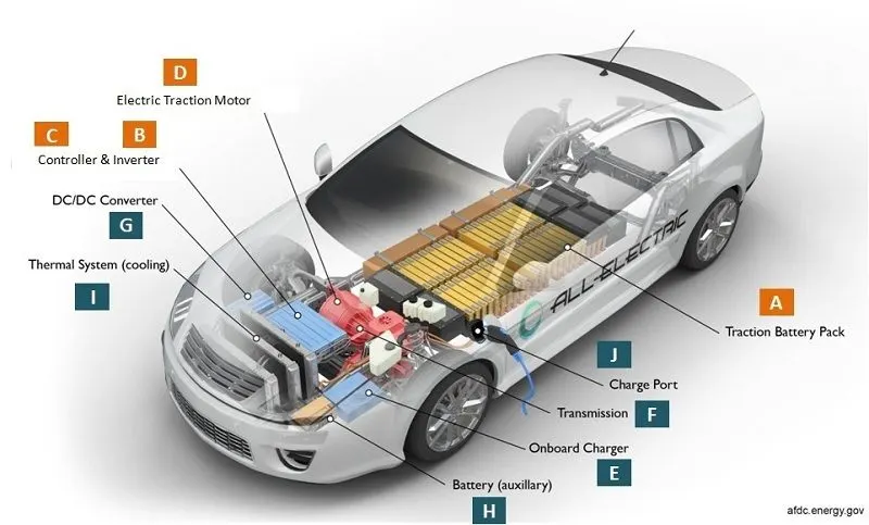
How Does An Electric Car Work
When the car pedal is pressed, then:
- Controller [C] takes and regulates electrical energy from batteries [A] and inverters [B]
- With the controller set, the inverter then sends a certain amount of electrical energy to the motor (according to the depth of pressure on the pedal)
- Electric motor [D] converts electrical energy into mechanical energy (rotation)
- Rotation of the motor rotor rotates the transmission so the wheels turn and then the car moves.
Basic Main Components of Electrical Vehicle.
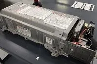
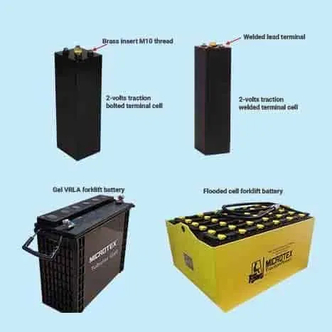
1) Traction battery pack
Traction battery pack is also known as Electric vehicle battery (EVB) . It powers the electric motors of an electric vehicle. The battery acts as an electrical storage system. It stores energy in the form DC current. The range will be higher with increasing kW of the battery. The life and operation of the battery depends on its design. The lifetime of a traction battery pack is estimated to be 200,000 miles. If it gets a signal from the controller, the battery will flow DC electrical energy to the inverter to then be used to drive the motor. The type of battery used is a rechargeable battery that is arranged in such a way as to form what is called a traction battery pack. There are various types of electric car batteries. The most widely used is the type of lithium-ion batterie.
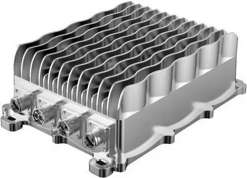
2) DC-DC Converter
The traction battery pack delivers a constant voltage. But different components of the vehicle has different requirements. The DC-DC convertor distributes the output power that is coming from the battery to a required level. It also provides the voltage required to charge the auxiliary battery.
3) Electric motor
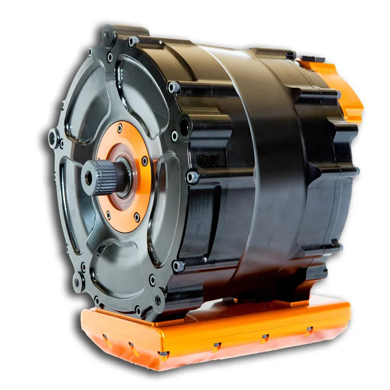
Electric traction motor is the main component of an electric vehicle. The motor converts the electrical energy into kinetic energy. This energy rotates the wheels. Electric motor is the main component that differentiates an electric car from conventional cars. An important feature of an electric motor is the regenerative braking mechanism. This mechanism slows down the vehicle by converting its kinetic energy into another form, and storing it for future use. There are basically two types of motors DC and AC motors.
4) Power Inverter
It coverts DC power from the batteries to AC power. It also converts the AC current generated during regenerative braking into DC current. This is further used to recharge the batteries. The inverter can change the speed of the.
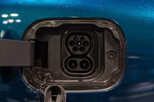
5) Charge Port
The charge port connects the electric vehicle to an external supply. It charges the battery pack. The charge port is sometimes located in the front or rear part of the vehicle.
6) Onboard charger
Onboard charger is used to convert the AC supply received from the charge port to DC supply. The on-board charger is located and installed inside the car. It monitors various battery characteristics and controls the current flowing inside the battery pack.
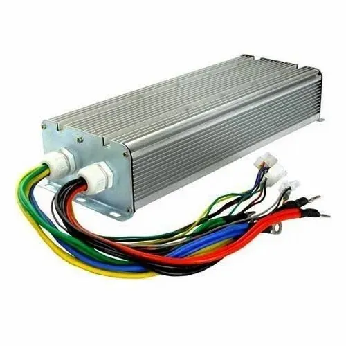
7) Controller
Power electronics controller determines the working of an electric car. It performs the regulation of electrical energy from the batteries to the electric motors. The pedal set by the driver determines the speed of the car and frequency of variation of voltage that is input to the motor. It also controls the torque produced.
8) Auxiliary batteries
Auxiliary batteries are the source of electrical energy for the accessories in electric vehicles. In the absence of the main battery, the auxiliary batteries will continue to charge the car. It prevents the voltage drop, produced during engine start from affecting the electrical system.
9) Thermal system(cooling)
The thermal management system is responsible for maintaining an operating temperature for the main components of an electric vehicle such as, electric motor, controller etc. It functions during charging as well to obtain maximum performance. It uses a combination of thermoelectric cooling, forced air cooling, and liquid cooling.
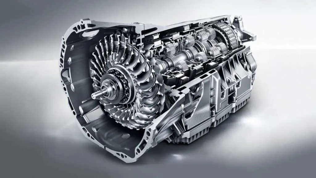
10) Transmission
It is used to transfer the mechanical power from the electric motor to the wheels, through a gearbox. The advantage of electric cars is that they do not require multi-speed transmissions. The transmission efficiency should be high to avoid power loss.
SIMULATION MODEL
Vehicle Body
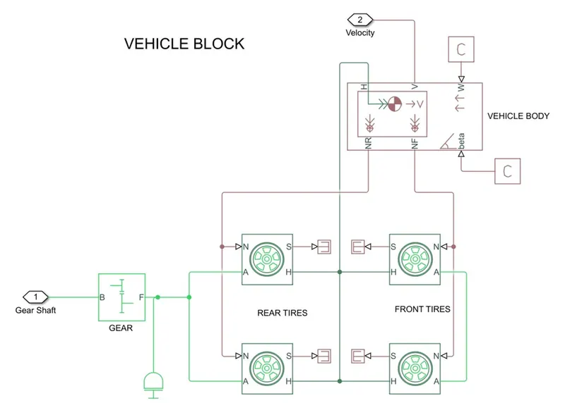
- Represents a two-axle vehicle body in motion.
- Accounts for body mass, aerodynamic drag, grade, externally-defined mass and centre of gravity of the vehicle body.
Input Ports
- W - Wind Velocity in m/s
- Beta - Grade angle in radians
Output Ports
- V - Velocity in m/s
- NR - Normal force on Rear Axle (N)
- NF - Normal Force on Front Axle (N)
Vehicle Body Parameters
- Vehicle body mass, Centre of gravity distance values and aerodynamic drag variables are modified.
- Pitch dynamics are kept ON with other variable values as default values.
Tire
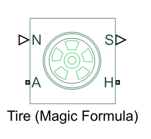
- Used to model a tire with longitudinal behaviour given by equation based on four fitting coefficients.
- The block can model tire dynamics under constant or variable contact surface conditions.
Input Port
- N - Normal force acting on tire, positive when force is acting downwards/towards the contact surface,
Output Port
- S - Slip value relative to tire and surface of contact.
Conserving Ports
- H - represents wheel hub which transmits thrust generated by the wheel to the body of the vehicle.
- A - represents axle on which the tires are mounted.
Gear
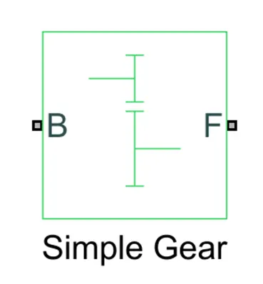
- A simple gear block is used to connect the motor to the rear axle of the vehicle.
- It represents the gearbox which connects the input shaft to the base gear and output from the fuller gear.
Conserving Ports
- B - port associated with input shaft (motor shaft).
- F - port associated with output shaft (axle / differential).
Simple Gear Parameters
- Gear ratio and output direction is modified.
- Meshing loss is kept constant and gear is having a constant efficiency throughout the simulation.
- Viscous losses and faults are kept at default conditions.
MOTOR & POWER CONVERTER
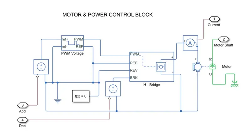
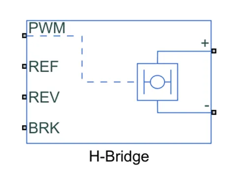
H-Bridge
The H-Bridge helps in controlling the power that is input according to the requirement. The output provided are converted voltage as per the controlled parameters.
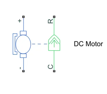
DC Motor
This is the DC Motor which would give the rotational power to the wheels and become the sole power generation source.
The DC Motors terminals are connected as mentioned below,
- + = Electrical signal to the motor Positive Terminal.
- = Electrical signal to the motor Negative Terminal.
- R = Casing of the Motor connected with the Mechanical Rotational Reference Block.
- C = Rotor Case connected to the Mechanical Rotational reference.
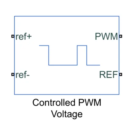
Controlled PWM Voltage
The Controlled PWM Voltage Block helps in keeping the Modulated Pulses as per the required pulses. So that the operations happens smooth and higher variations are not observed.
The Ports are connected as follows,
- ref+ = Reference Positive connected with the Acceleration Commands from the Driver Model.
- ref- = Reference Negative connected with the Deceleration Commands from the Driver Model.
- PWM = PWM connected directly to the H-Block.
- REF = REF connected directly to the H-Block.
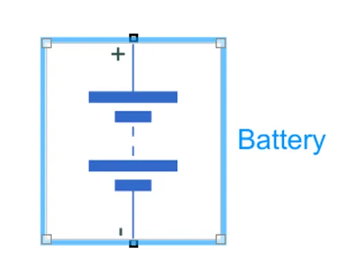
Battery
The battery is connected as the power source to the model so that the power could be generated and the same power is transmitted accordingly to all the operating sources.
The terminals connected are to,
- + = The positive terminal of the operating sources.
- = The negative terminal of the operating sources.
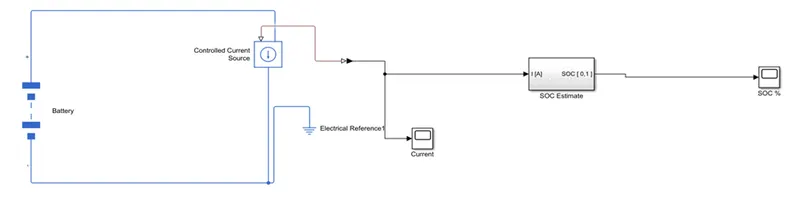
Battery Pack Components
The parameters considered of the battery are –
- The battery Nominal Voltage is rated as per 300 Volts,
- The internal resistance is as per 0.5 Ohms and others set as default.
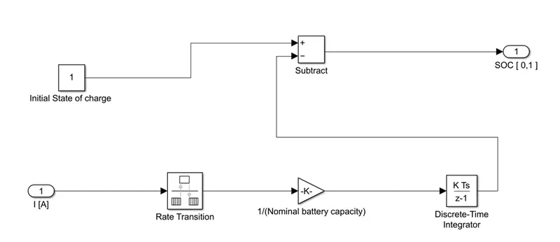
SOC BLOCK
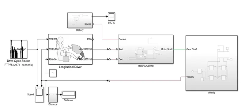
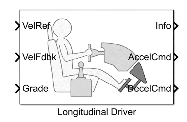
Longitudinal Driver
The Driver Model has the Input and Output Ports which are connected to the following,
Input Ports
- VelRef - input port associated with input reference velocity of the vehicle (m/s)
- VelFdbk - input port associated with velocity feedback from the vehicle which helps in smooth control of the system.
- Grade - input port associated with inclination of surface in degrees.
Ouput Ports.
- Info - Ouput port associated with a bus signal for acceleration, deceleration, error in velocity etc
- AccelCmd - Output port associated with acceleration commands with reference to input signal.
- DecelCmd - Output port associated with deceleration commands with reference to the input drive signal.
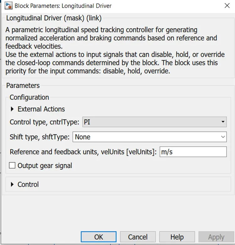
- Proportional-Integral Control Type is selected and the other control variables are kept as default values.
Drive Cycle Source
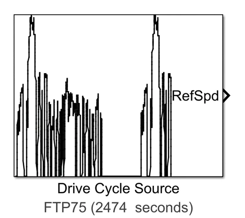
- Represents block which generates a drive cycle for a particular time. It is basically time vs speed data which resembles similar to that of a real-time driving condition with acceleration and deceleration in an irregular pattern.
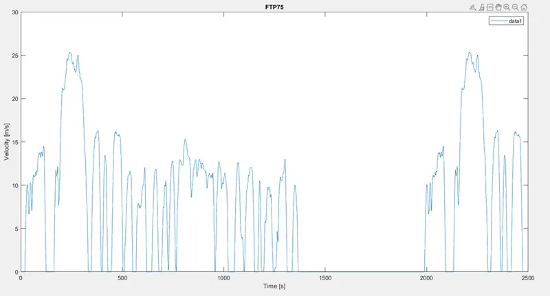
- By default, FTP75 drive cycle is selected.
- Simulation default time for FTP75 is 2474 seconds.
SIMULATION RESULT
Simulation is performed to valuate performance of the Designed Model through monitoring Speed Comparison of reference and Feedback signal along with State-of-Charge of the battery.
FTP75 Drive Cycle
The speed (m/s) from the drive cycle and speed feedback from the vehicle body is plotted in order to understand the response of model according to the drive cycle data. Simulation provided the following result in Speed Comparison.
State-of-Charge of Battery
Output
The SOC scope block helps in keeping track of the remaining battery capacity.
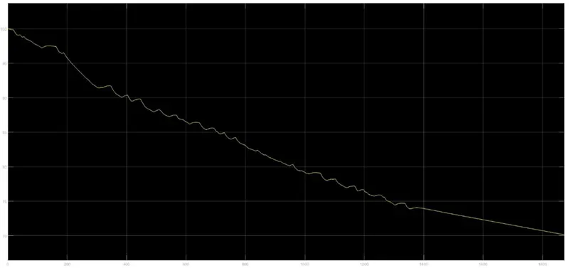
Wide Open Throttle
Speed
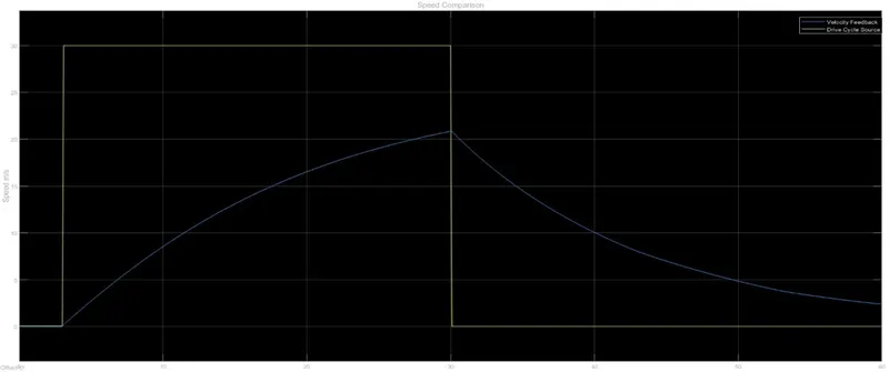
From this scope, we can see 2 signals. The blue signal represents the reference signal which originates from the drive cycle data whereas the yellow signal shows the actual velocity of the vehicle. The WOT drive cycle had been customized so that the vehicle begins acceleration under the WOT condition (i.e.. full power) at t = 5 seconds. This is supposed to be maintained till t = 20 seconds when the vehicle is supposed to begin deceleration. From t = 20 seconds to t = 30 seconds, the vehicle speed is back to 0m/s i.e.. rest. Because this is a reference signal, all the commands are instantaneous. This is why the increase and decrease in speed is very sudden within a fraction of a second. However, this effect will not be observed on the actual velocity of the vehicle. This is because in real world conditions, there are more considerations to factor in which will not make it possible for a vehicle to accelerate and decelerate as instantaneously as the drive cycle commanded. In the real world, the effects of rolling resistance, drag and road inclination make a difference because their presence would cause the vehicle's motion to deviate from the drive cycle commands. Other factors include, the vehicle's inertia and the inertia of the transmission system.
Observing the vehicle's actual velocity, as commanded, the vehicle begins at rest before accelerating under the WOT condition at t = 5 seconds. This acceleration is maintained till t = 20 seconds as the drive cycle commanded. At t= 20 seconds, the vehicle achieves a top speed of 26.8m/s. After t = 20 seconds, the vehicle begins to decelerate gradually till t = 30 seconds where the vehicle finishes with a velocity of approximately 7m/s. As mentioned earlier, the actual velocity could not match the drive cycle commands perfectly and this is due to several factors which were discussed above. In my model, I have not modelled a road inclination but I have used a wind velocity of 5m/s. I compared the effect of this wind resistance on the top speed of the vehicle to when there was no wind resistance. The effect was very insignificant, only affecting the top speed by 0.5m/s. However, the vehicle velocity has accelerated and decelerated as the drive cycle commanded. Obviously, the model is limited to the simulation time allotted. So if a longer simulation time is used, the vehicle may reach a higher top speed and may even decelerate back to rest.
Current
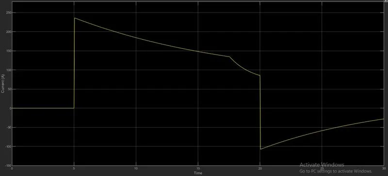
The current scope shows how the current flowing from the battery to the motor varies with the drive cycle time. As we can see, initially the current flowing through the circuit is 0A and this corresponds to the drive cycle commanding the vehicle to be at rest for this time period. At t = 5 seconds, when the vehicle is commanded to accelerate, the current instantaneously increases to a maximum current of 235.8A. This maximum current is achieved because at t = 5 seconds, the vehicle accelerates at maximum power under the WOT condition and so this will demand a high current from the battery. From t = 5 seconds to t = 17.5 seconds, the current decreases gradually to 134.3A. The current must have decreased over time because as the vehicle was accelerating, it required lesser current from the battery to continue accelerating. The highest current is always required when accelerating from rest due to the inertia of the vehicle. But once the vehicle is already in motion, it requires significantly lesser energy to continue accelerating. From t = 17.5 seconds to t = 20 seconds, the current flowing from the battery decreases more rapidly to 85.6A. This is because at this time, the acceleration of the vehicle began to level off meaning that the increase in speed in those 2.5 seconds was lesser than the increase from t = 5 seconds to t = 17.5 seconds.
After t = 20 seconds, the vehicle decelerates, causing the current to drop instantaneously to the negative axis to a value of -107.4A. There is now a negative current flowing due to regenerative braking. When the vehicle decelerates, the throttle is no longer applied and so the kinetic energy from the motion is converted to electrical energy fed back to the battery of the EV. This reverse flow of current is what causes the negative current measurement. From t = 20 seconds, the deceleration continues, however the current flowing through the battery decreases in magnitude. This is because at t = 20 seconds, the vehicle had reached its top speed and hence its maximum kinetic energy. So, at that point there was more kinetic energy which could be converted to electrical energy for regenerative braking. However, as the vehicle decelerates, there was lesser energy available for regenerative braking causing the magnitude of the current to decrease. The polarity of the current hence moves towards the positive direction because regenerative braking happens lesser and lesser until the vehicle comes to rest. At t = 30 seconds, the vehicle is still decelerating and finished with current measurement of -27.9A showing that regenerative braking is still occurring.
State-of-Charge of Battery
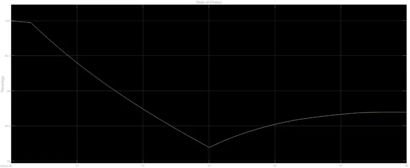
The SOC scope shows how the state of charge of the battery varies over the drive cycle time. The battery was modelled to begin with an SOC of 1 (100%) and so when the simulation begins, the SOC is at 1 until t = 5 seconds. This is because the drive cycle commands the vehicle to be at rest for that duration and so no discharge occurs from the battery. At t = 5 seconds, the vehicle is commanded to accelerate under the WOT condition and so the SOC of the battery decreases. Because the vehicle is accelerating at full power, the SOC falls from 1 but the rate of discharge decreases over the acceleration period eventually settling at a minimum SOC of 0.9914 at t = 20 seconds. This corresponds to the current flow from the battery because as the vehicle accelerates, lesser energy is demanded to increase the speed. As mentioned before, the greatest discharge occurs when the greatest current flows from the battery and this is during the initial acceleration period. As the vehicle speed increases, the acceleration decreases causing the current and hence the rate of discharge to decrease but in a mild fashion. At t= 20 seconds, the vehicle is commanded to decelerate and so the vehicle velocity decreases. This results in regenerative braking to occur which causes a negative flow of current back to the battery. Because this effect charges the battery, the SOC of the battery increases during the deceleration period. The SOC increases very gently from 0.9914 to 0.9935 and this is because the gets charges by the regenerative braking effect. The negative flow of current corresponds to the increase in the SOC of the battery. Since the vehicle is commanded to decelerate until t = 30 seconds, the vehicle speed decreases but does not reach 0m/s, so the vehicle is under regenerative braking for the entire period after t = 20 seconds.
CONCLUSION
A Detailed and in-depth parameterization of the motor control and vehicle block variables would make the model to exactly follow the reference velocity signal which would in turn enhance the performance of the system. Modification in battery block variables also might be helpful in reducing the Depth-Of-Discharge percentage which in turn provides higher mileage for the Vehicle in a single charge-discharge cycle.
I have a observed that the SOC of the battery used in my EV model did not get discharged in a way I had expected it to. This could be because the drive cycle commands did not push the EV model to its limits or it could be due to the fact that the battery model was very efficient and was suitable for the driving application. My EV model had also included some actual features of EVs such as regenerative braking and this was evident in the current - time and SOC - time graphs whenever the EV decelerated. If the duration of the WOT drive cycle was modified to be longer, I could have seen my EV model exhibit its true performance characteristics. For instance, the EV model may achieve its top speed and it may also have been possible to see the time it takes for the vehicle to decelerate from that top speed and hence the time taken for the acceleration.