Final Project: Design of an Electric Vehicle
.............. EV LIVE BATCH -16.......
Q)Create a MATLAB model of electric car which uses a battery and a DC motor. Choose suitable blocks from Powertrain block set. Prepare a report about your model including following:
Objectives:
1. System level configurations
2. Model parameters
3. Results
4. Conclusion....?
SOLUTION :
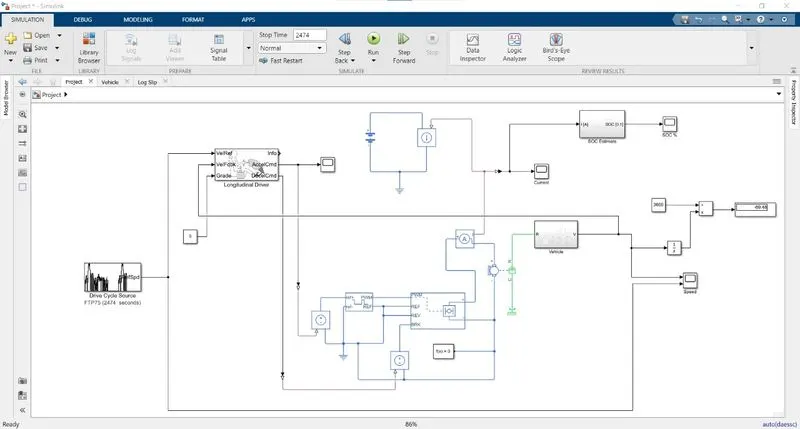
- The electric vehicle model has into divided into four major parts which include the primary components of the system.
- They are the drive source,motor & power controller,battery system and vehicle body.
- The prediction of performance and range of any vehicle is a very important concept for a design which can be done easily by programming techniques using mathematics and spread sheet programs such as MATALB & EXCEL.
- In order to determine the performance of an electric vehicle ,the important parameter to be focused on is acceleration and top speed where the vehicles always have poor response.
ELECTRIC VEHICLE MODEL:
VEHICLE BODY SUBSYSTEM:
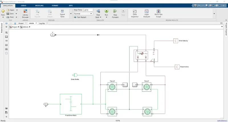
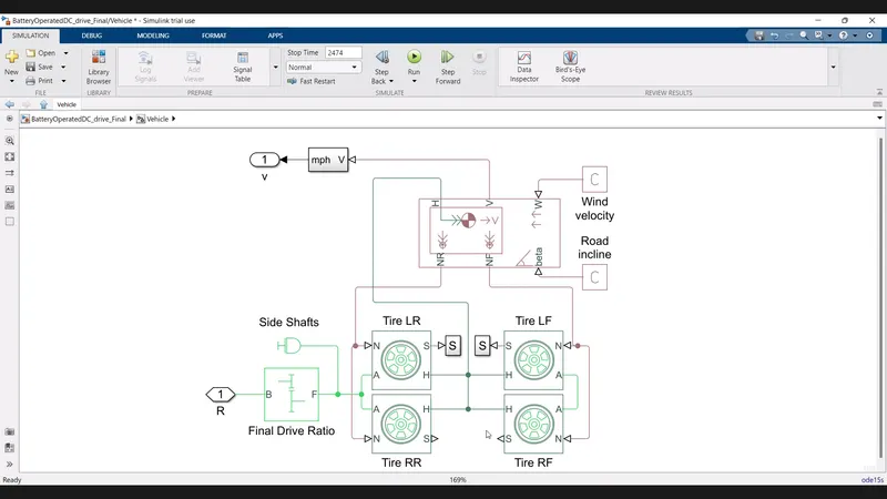
In this model , the vehicle body,simple gear ,differential and tires block are considered as a subsystem under the name vehicle body.
vehicle body:
- This is block represent a two-axle vehicle body in longitudinal motion.
- the block accounts for body mass,aerodynamic drag,road inclination and weight distribution between axles due to acceleration and road profile
- it has six terminals namely H,V,NF,NR,W and Beta
- CONNECTION H : it is the mechanical translational conserving port associated with the horizontal motion of the vehicle body
- CONNECTION V,VF NR are physical signal output ports for vehicle velocity
- rear wheel forces respectively
- CONNECTION W and BETA are physically signal input ports
- if the variable mass is taken into account ,then the centre gravity CG,and M ports
- come into play by accepting two element vectors respectively X AND Y distance from vehicle CG to additional mass load CG
VEHICLE BODY BLOCK PARAMETER:
MAIN:
Mass : 800 Kg
Number of wheel per axle :2
Horizontal distance from CG to front axle : 1.7m
Horizontal distance from CG to rear axle : 2m
CG height above ground : 0.5m
Externally- defined additional mass : off
gravitational acceleration : 9.81m\s^2
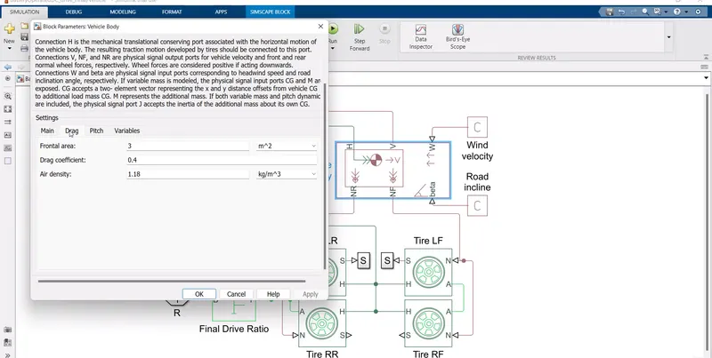
DRAG:
frontal area: 3m^2
drag coefficient : 0.4
Air density:1.18kg\m^3
- The frontal area and the drag coefficient should be kept as low possible so that the power requirement to overcome the aerodynamics force can be reduced
- The mass of the vehicle also has the effect on the vehicle performance ,range and cost of an electrical vehicle
- when the vehicle climbs a hill,there will be kinetic energy loss occur when the vehicle is accelerating and decelerating .
- it mainly affects the rolling resistance ,power and energy
TIRE BLOCK:
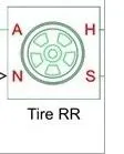
- This is block represent the longitudinal behavior of a highway tire characterized by the tire magic formula
- H terminal of the rear wheels and front are connected H port to the vehicle body
- N terminal of the rear wheels are connected to the NR port of the vehicle body
- terminal are axle ports of rear wheels that are connected to simple gear body ,through these ports
- S terminal are connected to ps terminators so that they remain inactive
TIRE (MAGIC FORMULA):
PARAMETERS:
MAIN:
parameterize by: Load -dependent magic formula coefficients
Tire nominal vertical load : 4000N
Magic formula C-coefficient parameter,p_cx1: 1.685
magic_formula D-coefficient parameter,
[p_Dx1 p_Dx2] : [1.21-0.037]
magic_formula E-coefficient parameter, : [0.344 0.095 -0.02 0]
magic_formula BCD -coefficient parameter,:[21.51 -0.163 0.245]
GEAR BLOCK :
- This block represents fixed ratio gear
- it has two terminal B and F represents base and f represent the follower of the gear and are mechanical rotational conserving ports
- The F terminal is connected to the rear axle and the B terminal is connected to the DC motor
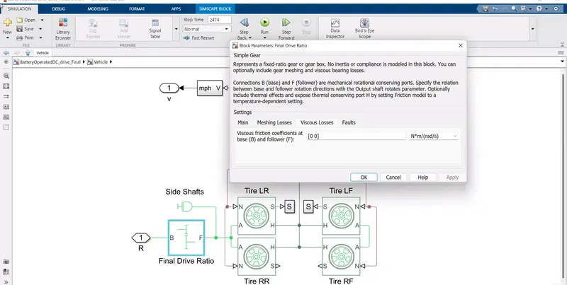
- SIMPLE GEAR is represent a fixed ratio gear box.
- No interia or compliance is modeled in this block
- you can optionally include gear meshing and viscous bearing losses
SETTING:
viscous friction coefficient at base (B)and follower (F):[0 0] N*m\(rad\s)
- Here the gear ratio is changed to o to o increase times the torque produced by the motor .
- Electrical vehicle transmission is much simpler as the motor provides motion from zero speed upward i.e by just conecting a simple gaer ratio provided with differential .
DIFFERENTIAL BLOCK:
- Differential represent a differential which is arranged as a plantary bevel gear train equipped with an additional gear tranmission between the driveshaft and the carrier
- no compliance is modeled in this block
- Default values of the block parameter are taken for simulation
- the differential provides the tractive force equally to both rear and front wheels
- if the differential is removed , then a powerful electronic controlled is needed to provided equalized torque to all the wheels
POWER CONTROLLER:
- when the power controller is the main components of the DC motor ,H -bridge converter and controlled PWM voltage source
DC MOTOR BLOCK:
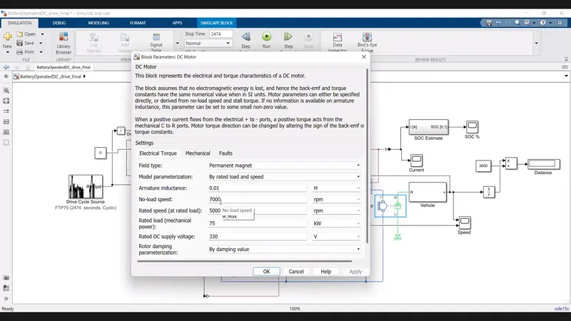
- The block assumes that no electromagnetic energy is lost
- hence the back -emf and torque constants have the same numerical value when in si units
- motor parameter can either be specified directly from no-load speed and stall torque
- that we connect the casing terminal c to the mechanical rotational reference block
- the R port is connected to the simple gear B terminal port
SETTINGS OF DC MOTOR:
H -BRIDGE :
- This is block represent an H-bridge motor drive
- this is can be driven by the controlled PWM voltage block inPWMC or average mode
- in PWM mode ,the motor is powered if the PWM port voltage is above the enable threshold voltage
- if REV port voltage is greater than the reversed threshold voltage , then the output voltage polarity is reversed
- if the BRK port voltage is greater than the braking threshold voltage ,then the output terminal are short -circiuited via one bridge arm in series with parallel combination of a second bridge arm and a freewheeling diode
- the pwm port of the H-bridge is connected to the controlled PWM voltage source block
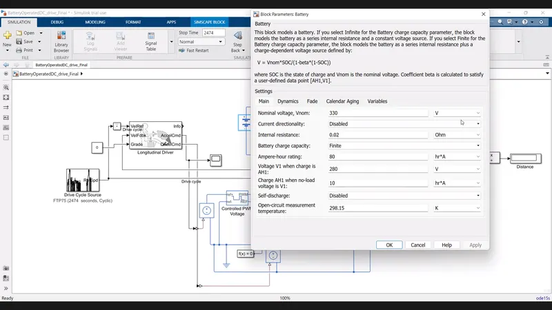
BATTERY :
- this is included a battery of lithium -on ,a controlled current source,bus selector
- the port1 is connected to the current sensor in the power controller
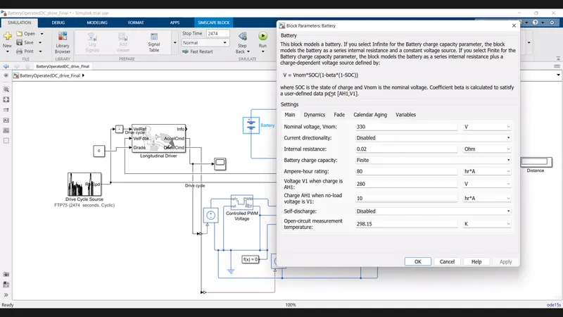
- if a select infinite for the battery charge capacity parameter , the block models the battery as s series internal resistance and a constant voltage source
- V= Vnom *SOC\(1-beta*(1-SOC)
- where SOC is that state charge and Vnom is the nominal voltage
- coefficient beta is calculated beta is calculated to satisfy a user -defined data point [AH1,V1]
VEHICLE SUBSYSTEM:
GAIN :
VEHICLE BODY:
SIMPLE GEAR:
LONGITUDINAL DRIVER BLOCK is takes the responsibility of calculating acceleration by taking two input one form the drive cycle velocity input and the other one from vehicle traction velocityat each one second of time interval and is repeated provides the input to the voltage source till the end of the drive cycle.
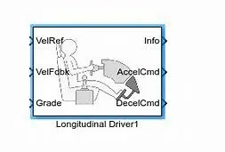
- A parameteric longitudnal speed tracking controlled for generating normalized acceleration and braking command based on reference and feed back velocities
- All the defaulit data provided in the driver block is considered as input to the simulation .
- if needed the data can be varied and observe the simulation of the vehicle
DRIVE CYCLE :
- The range of electric vehicles is the major problem faced by the automobile industry because strong electrical energy efficient is a very task for engineer
- this is a critical issue in the design of any electrical vehicle
- now the model ,the FTP75 drive cycle is choosen and with this cycle input reference ,simulation of the model is done
- using this data motor efficiency can be found and also the electrical power going into the motor
- this is calculation is represented every one second till the end of the cycle
CONTROLLED VOLTAGE SOURCE: provides constant voltage to the PWM voltage source
ELECTRICAL GROUND: it is needed to discharge the excess charge flowing through the devices .so all negative terminal of the devices are connected to the ground
PS TERMINATOR: this is block is connected to the unconnected terminal which are inactive in the model
PS CONSTANT: this is block is constant and is taken from the simscape library
CONTROLLED CURRENT SOURCE: it is used to provided current to the battery and is a physical signal
BUS SELECTOR: this is block accepts bus as input which can be created from bus creator and output using a bus object
SOLVER CONFIGURATION: each physical network represnted by a connected simscape block diagram requires solver setting information for simulation
RESULTS :
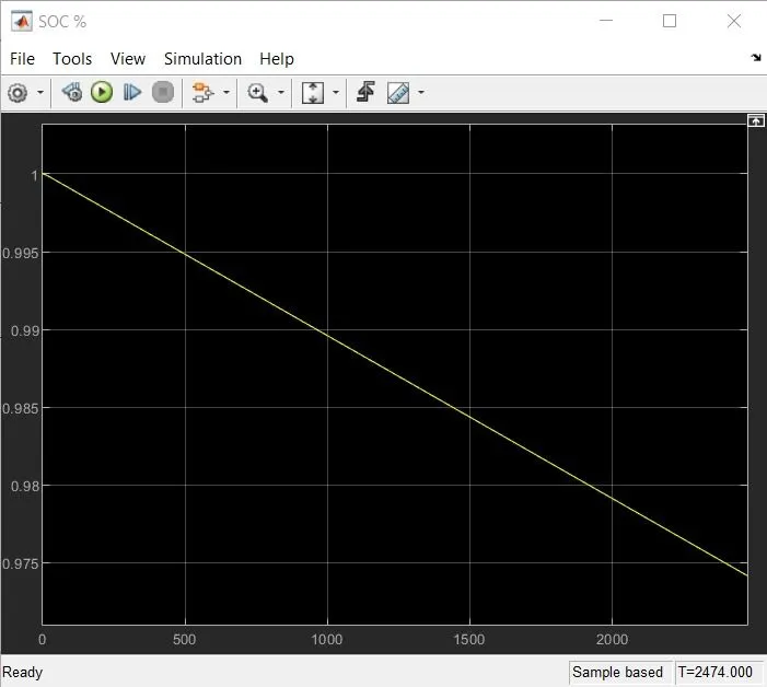
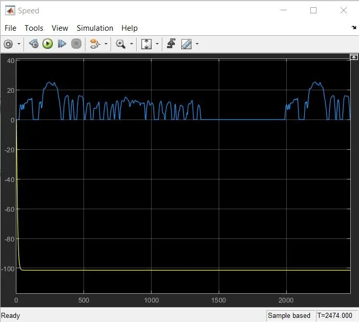
THEREFORE THE SIMULATION STOP TIME IS 2474SECONDS
CONCULSION:
In this using programming techniques of matlab ,simulations can be easily performed and can predict the vehicle which is cost and time -effective.......................