Final Project: Design of an Electric Vehicle
PROJECT 2 – DESIGN OF AN ELECTRIC VEHICLE
AIM –
- Create the MATLAB model of an Electric car which uses Lithium-Ion Battery & Induction Motor. Choose suitable blocks from Powertrain Blockset.
INTRODUCTION -
An EV is defined as a vehicle that uses an electric motor or traction motor for propulsion as opposed to an internal combustion (IC) engine used by conventional vehicles. Electric vehicles use electricity for power instead of fossil fuels s conventional vehicles would & because of this difference, electric vehicles don’t produce any exhaust gases or pollution. The power needed for the operation of an EV comes from variety of sources such as batteries, generators & collector systems. batteries fitted into the body of an EV are capable of high energy densities in order from them to meet the power demands and range requirements. Generators are machines that generate electrical energy from an input of mechanical energy & are a part of electric motors & they operate during braking to produce phenomenon of ‘Regenerative Braking’. Collector systems are off vehicle systems which allow for the charging of an EV from homes or public charging stations. The electricity used for charging in these systems are generated from solar panels which can be used by the grid or by homes of an EV owners so that they can charge their vehicles more conveniently.
EVs are increasing in demand in recent years due to the need to reduce the vehicle emissions which are damaging the environment. Government incentives & private companies are working on the schemes to quicken the adoption of electric vehicles since EVs don’t produce any emissions they are more environment friendly than conventional vehicles. The generation of the electricity used to charge the vehicles also comes from solar energy (A Renewable Energy Source) also fossil fuels are depleting & hence EVs can meet the same performance requirement standards of conventional vehicles & even surpass that of theirs which has been seen with the Automotive company Tesla. The Tesla Model 3 is the bestselling EV in the world & is capable of range of 350Km on single charge. It also has an acceleration of 0-60 Mph in 5.5 seconds nd the top speed of 130 Mph.
EVs offer several advantages over conventional vehicles besides the lack of pollution lack of need to rely on fossil fuels. One is that EVs are more efficient meaning that they offer more MPGe (Miles/Gallon Gasoline equivalent) meaning that you will spend lesser on recharging an EV than you would o refuel the conventional vehicle. This is because the more efficient the EV is the more distance you will travel with available energy. In the US Tesla owners can charge their EVs for free at their charging stations for life which results in significant savings in fuel. Regenerative braking in the EVs adds to their efficiency as the unused energy in the braking is reused purposefully. Another benefit is that EVs have fewer moving or rotating parts & this means lesser maintenance costs that you would have with IC engine vehicles. E.g. Changing Oil, Transmission fluid. This in the long term would give better savings tan you would get with the conventional vehicles. Lesser moving parts means there is less friction between them and hence quieter operation.
In spite of these advantages, it is going to be difficult for worldwide adoption of EVs for several reasons. One is convenience. In order to EV to dominate the automotive market, there is need for more convenient ways for consumers to be able to charge their vehicles. There is need for several charging stations on the highways & the roads & this can be done when every home has the solar energy generators. So it will as easy as IC engine filling fuel from stations. Another reason is the cost of EVs. EVs are still relatively new technology & only account for 2-3% of the worldwide market. This is because they cost considerably more than conventional fuelled vehicles due to high cost of batteries & electrical components. But the cost of batteries is getting cheaper over time & manufacturers are developing newer and more efficient ways for battery production. The goal is to produce ‘million miles’ batteries & it will be revolution in the automotive sector. another disadvantage is that the components in the EV operate at very high voltages & currents & this can be hazard if the components explode or don’t work as they should.
A compromise between ICEs and EVs exists as Hybrid Electric Vehicles (HEVs). HEVs combine an IC engine with an electric propulsion system to produce ‘Hybrid’ between the 2 different classes of vehicles. The purpose of this is to use power available from electric powertrain to improve the fuel economy of the vehicle so that it doesn’t rely solely on petrol/Diesel which it uses conventionally as a fuel. This in turn it will also improve the overall performance of the HEV. The ICE can also be used to power the electric motor to charge the battery or used directly in the electric drive motor & generator in one. HEVs also implement the regenerative braking to recharge their batteries among other features used in EVs. Compared to EVs, HEVs represent more of the automotive market with 19% market share on all automobiles in the world. This is because the HEVs still run on the fossil fuels partially which is still more convenient as a fuel source in the most parts of the world. The all-time best selling EV in the world is Toyota Prius.
In this project we will be modelling EV with DC motor & Battery system using Simulink Software. The components exist as blocks in the Simulink Block Library. Modelling of this EV is for a Drive Cycle & measure the velocity characteristics & current & SOC characteristics of its battery system.
Components used in EV –
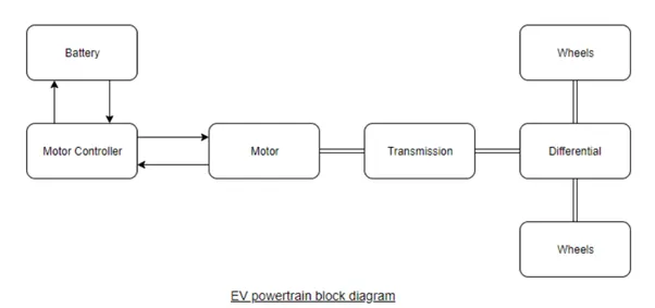
- Electric Traction Motor.
- Cooling system.
- Power Electronics Controller.
- Auxiliary Battery.
- Traction Battery Pack.
- Transmission.
- Converter.
Together these components when merged with a usual vehicle gives us an EV. There are many system level configurations which have to be made & considered for efficient operation of the vehicle. The vehicle test has to go through several regions where it’s extremely cold & where it is extremely hot. In all these components the major cost contribution is by the traction motor & the batteries & everything doesn’t cost at that higher range.
Batteries store an electrical energy needed to power the EV in all of its systems and needs. Power converters convert the power coming from the battery to a usable form for the motor. This conversion can be from DC to AC or Vice a Versa & can even be between 2 different magnitudes of DC to DC or AC to AC. Motor controllers are electronics which control the amount of power delivered to the motor via controlled signals so that the motor is running as commanded. The motor is used for propulsion in order to move the vehicle in forward or reverse motoring. The generator is the part of the motor & just works in the opposite method to the motor. When braking the vehicle can generate electricity & send this power back to the battery, charging it (regenerative Braking). The transmission system is needed for the vehicle to change speed as it accelerates/deaccelerates. The wheels are needed for traction on the roads & depending on the powertrain, the EV may be FWD/RWD (Forward or Rear Wheel Drive). If the vehicle is a FWD only the front axle wheels produces propulsion i.e. Rotate from motor effect & it its’s an RWD, the back axle wheel produces it instead. All wheel drives (AWDs) also exist where the front & rear wheels work together to produce propulsion.
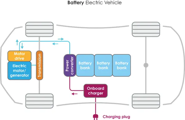
Reference Material - https://www.youtube.com/watch?v=tM9Akdo8QeA
System Level Configuration –
The major components forming the complete system are –
- Drive Cycle.
- Driver.
- H-Bridge.
- DC Motor.
- Battery Source.
- Controlled PWM Voltage.
- Vehicle & Others.
The model of an EV in Simulink, we need to model for mentioned components separately & then have them work together. All the main components re available in the library of Simulink Blockset & we will be adding each components & configuring its parameters to fit the requirements of the model. Now we will modify main vehicle body.
Vehicle Body –
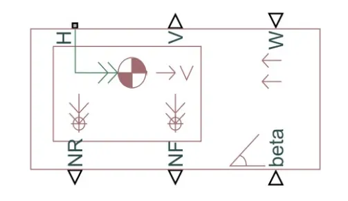
To model a vehicle body, first we need to add the vehicle body block as shown below –
This block contains six ports which can be used to model the various aspects of the vehicle body. These ports are mentioned with description below –
H – this stands for ‘Hub’ & Is used to connect Hubs of the wheel to the main body of the vehicle.
V – This is physical signal output port which stands for ‘Velocity’ & is used to output the speed/velocity at which the vehicle is moving at.
W – This is physical signal input port & allows us to model a ‘Headwind ’acting on the vehicle by giving a speed for it.
NR – This is a physical signal output port to model the rear wheel normal forces.
NF - This is a physical signal output port to model the front wheel normal forces.
Beta – This is physical signal input port & allows us to model the vehicle on an inclination angle to create the effect of a hill climbing force.
If we double click the vehicle body block, we can see & modify its parameters as shown in image below –
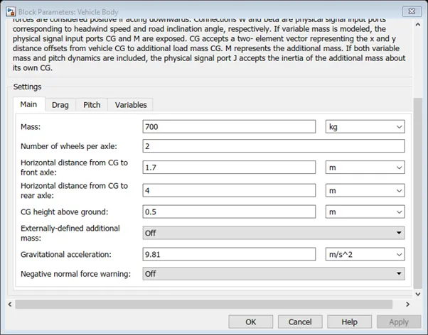
As you can see we are able to modify various parameters of the vehicle body for e.g. Mass, No. of wheels per axle, distance of the centre of the gravity to the front & rear axles. These are main parameters & have been left with default values assigned when the block was added to the workspace. The next tab shows the parameters for ‘Drag’ & this is shown below –
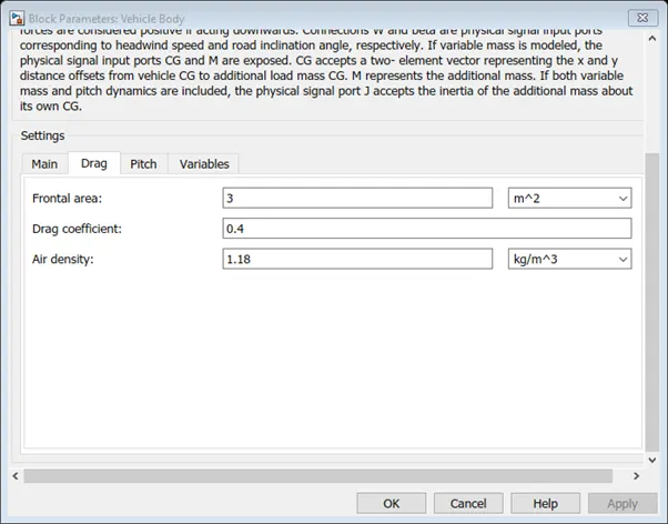
We can see from this image that the parameters of frontal area, drag coefficient & air density can be modified in order to effect the drag force acting on the vehicle. In this case we have changed only drag coefficient to 0.5 from the default value 0.4 in order to model for the typical sedan. Air density & frontal area are normal for this type of vehicle.
Tyres –
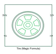
Tyres used in EV model are named as ‘Magic Formula’ Tyres. There are several blocks that can be used for modelling of a vehicle but magic formula tyres allows us to model longitudinal behaviour of vehicle tyres on highways. They also allow us to model extra effects such as inertia, stiffness which allow for greater accuracy of real world conditions. The Magic Formula tyre blocks are shown below -
We can see that it has 4 ports and these are -
N – This port stands for ‘Normal’ & it is the physical signal input port for the normal force acting on the tyre & is considered positive n the downward direction.
S – This port stands for ‘Slip’ & it is the physical signal output port & it reports the slip acting on the tire.
A – This port stands for ‘Axle’ & is the mechanical rotational conserving port for the wheel axle.
H – This Port stands for ‘Hub’ & is the mechanical translational conserving port for the wheel hub through which the thrust developed by the tyres is applied to the vehicle body.
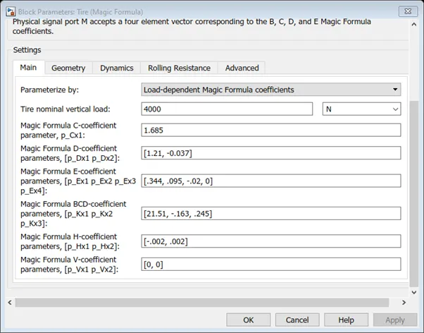
Double clicking Magic Formula Block gives us this parameters –
Main –
Geometry –
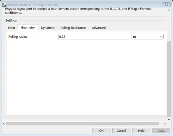
The image shown below shows us the parameters for the tire geometry. This is only parameter that can be modified & it is the rolling radius and his been set to a nominal value of 0.38m.
Dynamics –
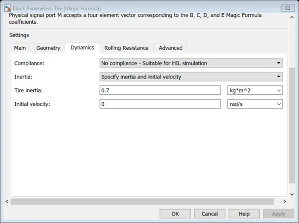
This next parameter is the Dynamics of the magic formula tires. This is where we can model additional effects e.g. tyre inertia & the initial velocity if we are modelling specify those 2 conditions –
Rolling Resistance –
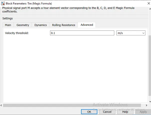
Here we can model rolling resistance parameters on the tires & chosen to switch ON the rolling resistance force on the tyres. Also, I have selected a constant coefficient of rolling resistance of 0.015 & velocity threshold of 1e-3.
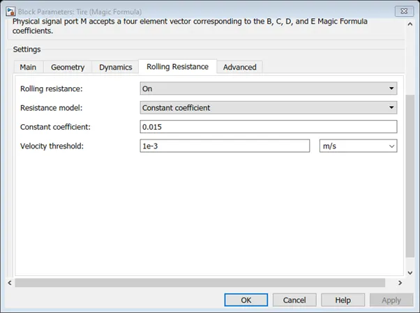
Advanced –
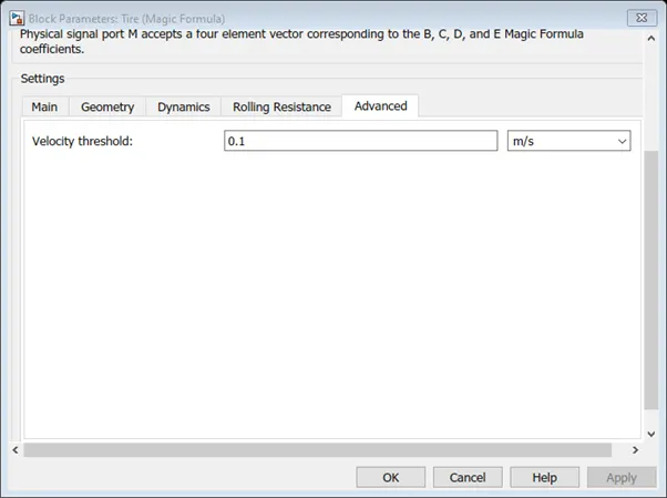
Finally, the last parameter of the Magic Formula tires is the Velocity Threshold & this has been set to 0.1m/s. below this speed the block will not model any of the before mentioned effects of motion on to the tyre hence it is called ‘Threshold Velocity’.
Slip –
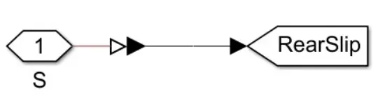
The ‘S’ port on the LR & LF tyres are modelled with a certain degree of slip using a small subsystem. The system used the PD-Simulink converter which will be used again in later on for other systems in this EV model. The Slip subsystem used in ‘Magic Formula’ tyres is shown below –
Gear –
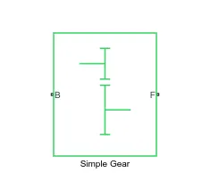
Next, modelling of the transmission system takes place of the EV. Utilization of ‘Simple Gearbox’ so as to simplify the Transmission system parameters. This block models the Gear System with a fixed gear ratio with no inertia effects, however we can modify the effects of the meshing of the gear tooth. The simple gear is as shown below-
Double clicking simple gearbox block takes us to its parameters –
Main –
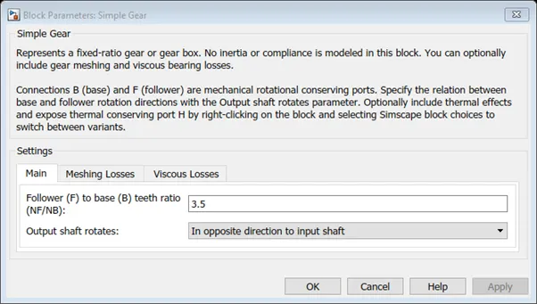
The main parameters of the simple gear are the follower of the base teeth ratio & this has been set to 3.7. I have also specified that the output shaft rotates in the same direction as the input shaft as opposed to the opposite direction of the input shaft.
Meshing Losses –
The meshing losses I have selected follow a constant efficiency friction model with an efficiency of 0.82 & the follower power threshold of 0.002 W.
Side Shaft –

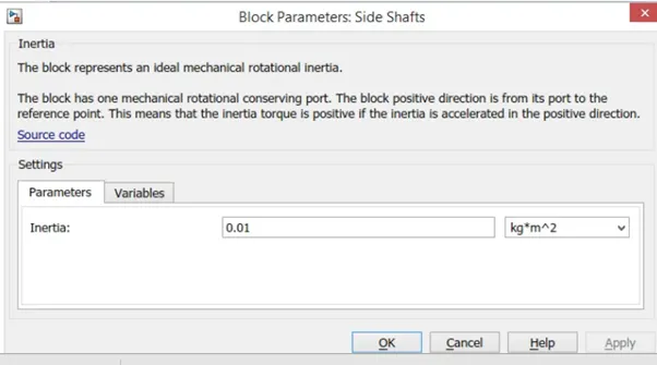
An inertia block has been added to the workspace to provide an ideal mechanical rotational inertia for the simple gear block. This block has only one mechanical rotational conserving port & the positive direction of the block is from the port to the reference point which would be the simple gear in this case. The inertia torque acts in the positive direction and inertia accelerated to positive direction.
The inertia block parameters only allow for us to modify the inertia and this parameter has been kept to a default value of 0.001.
Wind & slope –
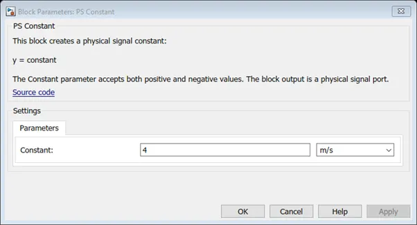
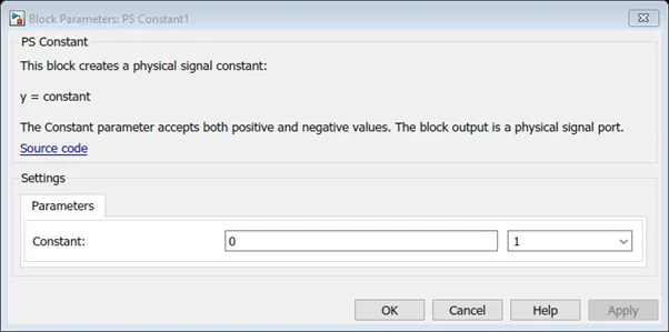
As mentioned earlier, the velocity block allows us to model the effects of wind resistance & road inclination through the “W” & “Beta” ports respectively. in this model PS-Constant block is used to model the parameters of wind & road inclination on the vehicle’s motion. For the wind effect, I have given a constant signal of 5 m/s & this acts as opposite direction to the direction of motion. i.e. Headwind. For the road inclination, I have given a constant signal of 0. The block parameters of wind & slope effects are shown below –
Velocity Subsystem -
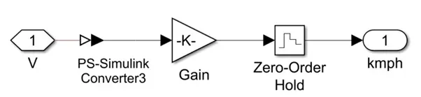
The velocity port which outputs the velocity signal of the velocity block has been modified. By default, the velocity signal that is output from the velocity block is measured in miles per hour. To change these units, I have implemented a small subsystem from the output of the velocity port. The subsystem uses following blocks –
Ps-Simulink Converter – This block will convert the physical signal of velocity to a logical signal.
Gain – This block uses a multiplication factor of 1.6 to convert the miles per hour units to kilometres per hour.
Zero – Order Hold – This block is used to implement a zero order hold sample period.
This subsystem is shown below –
Vehicle Body Subsystem –
As seen in the diagram above, the various blocks are connected to model the vehicle body. 4 Magic Formula block tyres are used as the vehicle have 4 tyres, 2 on each axle. The tyres are LR, LF, RR, RF (left rear, Left Front, Right Rear, Right Front). The normal ports of each tyre are connected to the appropriate NR & NF ports on the vehicle body block. The hubs of each tyre are connected together & an extra connection is made from them to the vehicle body block. The ‘S’ ports of the LR & LF tyres have been modelled with slip using small subsystem. The simple gear & inertia blocks are connected to the axle port of the tires. The wind velocity & road incline is provided with constant physical signal of 5 m/s & 0 degrees respectively. the velocity port has been connected to the velocity subsystem & the connection from the subsystem is open to the ‘V’ port. The base port of the simple gear has been left open to the ‘R’ port to take in a rotational signal. If all these connections are made all of these components can be selected & made it to a subsystem as shown below-
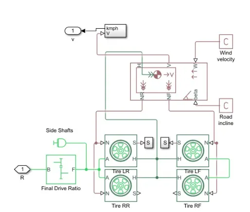
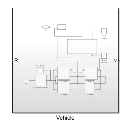
The subsystem is created so that less space is taken up in the workspace & only open ended connections are to be modified.
Motor –
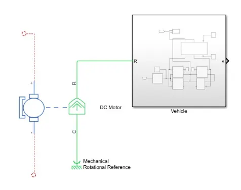
For the EV model, I have selected to use DC motor block as the motor. This is because the DC motors are easier to model & have fewer parameters to modify for a particular application. For this model D.C. motor will work just fine. The D.C. Motor block is shown below –
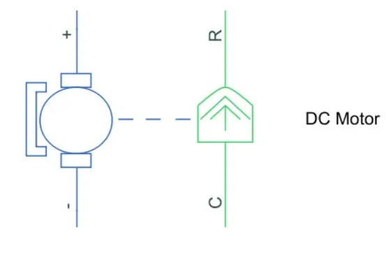
As we can see there are 2 sides to the block: The mechanical side on the right & the electrical side on the left. The mechanical side has 2 ports C & R; C refers to the casing & R for the rotation of the rotor which produces a torque. The electrical side has a positive & negative terminal for the voltages to be applied. If the positive voltage is to be applied to the D.C. motor block from the positive to negative terminal, a positive torque will act from the C port to the R port the direction of the torque produced by the D.C. motor can be changed by changing the signs of the back emf or the torque constant. The C port on the mechanical side needs to be connected to a mechanical rotational reference because it will be stationary. The R port will be connected to the open connection of the simple gear from the vehicle body block. The positive terminal on the electrical side is connected to the positive terminal of a power converter which is in this case will be ‘H’ Bridge.
The mechanical rotational reference is shown below –

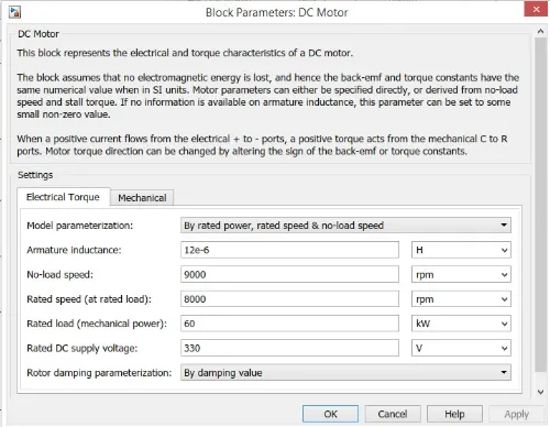
Double clicking the D.C. Motor block takes us to its parameters. The electric torque parameters are first considered. Here I have chosen to parametrize the block “By Rated power, Rated speed, No-Load Speed”. This lets us to modify the parameters such as DC supply voltage, Rated Load and all the values are kept as default except for No-Load Speed, Rated Load & the D.C. Supply Voltage which were changed to the values shown in the image below –
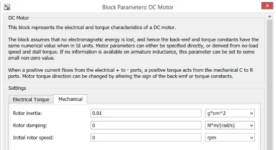
In mechanical parameters, we can modify rotor inertia, initial rotor speed, however these values are kept to their default settings.
Once the D.C. block has been parameterized the following connections need to be made
Power Converter –
The power converter is needed to provide power of the correct form & magnitude from one component to another. In the case of EVs a power converter is needed to provide a D.C. voltage from the battery of the EV to the D.C. motor so that it can operate properly with the required parameters. As mentioned earlier I have used H-Bridge motor drive as power converter. Its block is shown below –
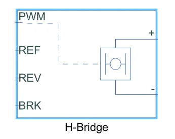
The H-Bridge has 2 sides to it- The left side is for controlling the voltage signals & the right side is for the terminals to provide the controlled voltage to the DC motor. The left side ports of the H-Bridge block are –
PWM – This stands for Pulse Width Modulation which will provide the voltage pulses to the H-Bridge either in the PWM or Average mode.
REF – This stands for reference.
REV –This stands for Reverse.
BRK –This stands for Brake.
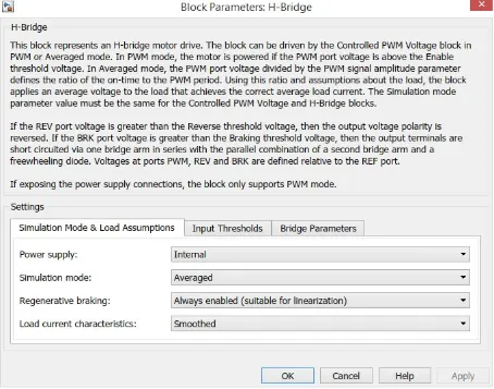
The main parameters are for the simulation mode & load assumptions of the H-Bridge. I have selected the H-Bridge to run on an internal power supply with an averaged simulation mode instead of PWM mode will result in significantly longer simulation times compared to using the averaged mode. & set the load current characteristics to smoothed option.
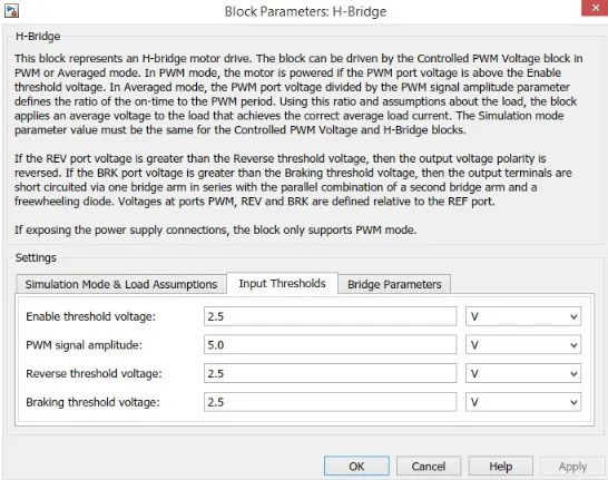
The next parameters of the H-Bridge are its inputs thresholds, here we can set the various voltage limits of its 4 left hand side ports. These values are as their defaults.
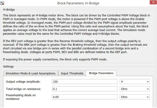
The last parameter for the H-Bridge block is Bridge parameters. Only1st parameter of ‘Output Voltage Amplitude’ was modified. This is because the DC motor has been parameterized to run on a DC voltage supply voltage of 330 V. so this is same value used for output voltage amplitude.
Once these parameters have been applied, close the parameter settings. The connections of the block will be made later on.
Controlled PWM Voltage –
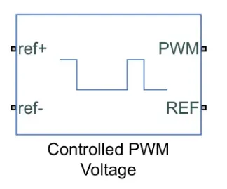
Next, I have used controlled PWM voltage block to control the Pulse Width Modulation Voltage to the H-Bridge Block. The block will output the PWM voltage through its ‘PWM’ & ‘REF’ ports which will feed into the same ports found on the H-Bridge block. If the Pulse is low the output voltage is considered 0 V however if the pulse is high the output voltage will be equal to the output voltage amplitude which has been set to 330V in the H-Bridge block. The pulses of voltage created by this block are dependent on duty cycle which is the ratio of the time that the switch is ‘ON’ to the time taken for one cycle (which is the time for which the switch is ON &OFF). The Duty cycle is set by the input of the controlled input PWM voltage block.
The Duty cycle formula is given by –
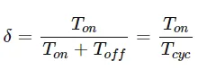
= Duty Cycle.
Ton = ON Time.
Toff = OFF Time.
Tcyc = Time taken for 1 cycle.
Controlled PWM Voltage block is shown below –
The block parameters are shown below –
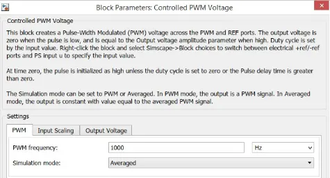
The first main setting is PWM parameters. Here all the parameters are maintained at their default values. ‘Averaged’ simulation mode is chosen so that the average value of the voltage pulses is generated & fed into the H-Bridge which will allow for quicker simulation times. Just like the H-Bridge block parameters. The remaining parameters of the ‘Input Scaling’ & the ‘Output Voltage’ are unchanged.
Controlled Voltage Source –
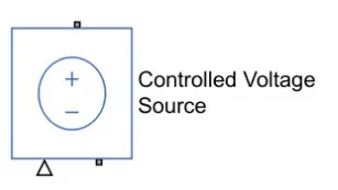
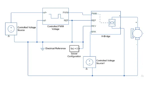
The Input parameters of the controlled PWM voltage block are still unconnected and that is because they require a controlled voltage source to provide the voltages to produce the voltage pulses to be fed into the H-Bridge. For this Controlled Voltage Source Block is useful because it will provide necessary voltage that is powerful enough to maintain the voltage at the output regardless of the current that passes through it. In this model 2 Controlled Voltage Sources Blocks are used. One block is used to provide the voltage for the acceleration of the vehicle & other is to provide deceleration of the vehicle. The controlled voltage block is shown below –
Electrical Reference –
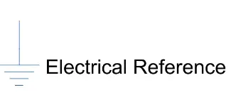
The electrical reference block is used to create a grounding effect for the electrical circuits. Any model that uses electrical or electronics components will need to have at least one electrical reference block in it. In EV modelling we are using 2 electrical reference block on 2 occasions. The 1st is to create an electrical ground between the controlled voltage source, Controlled PWM Voltage & the H-Blocks. The 2nd is for the Battery system which will be modelled afterwards. The electrical reference block is shown below –
Solver Configuration -
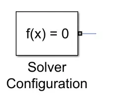
The Solver configuration block is used to solve any necessary equations in a model & in my case, I have used them in the connection to the ‘REV’ port of the H-Bridge Block. The solver configuration block is shown below –
The image below shows the connections that can be made with the components discussed till this point-
Longitudinal Driver –
The longitudinal driver block is used for giving normalized acceleration & deceleration commands to a controller based on 2 sets of data. The first data set is the reference velocity & the second dataset is the feedback velocity. the longitudinal driver block has following ports-
The longitudinal driver block is shown below –
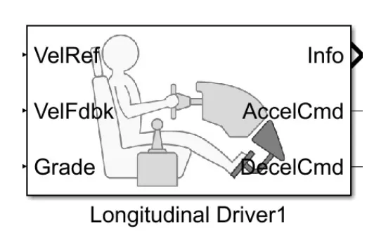
VelRef – This stands for reference velocity & it is the velocity data provided from a drive cycle source.
VelFdbk – This stands for the feedback velocity & it is the velocity data provided from the velocity body’s velocity port which outputs the velocity data.
Grade – This port provides the grade or inclination angle for the surface on which the vehicle is travelling in degrees.
AccelCmd – This port provides the acceleration command to a controlled voltage source.
DecelCmd – This port provides the deceleration command to a controlled voltage source.
Grade – The Grade port of the longitudinal driver block is connected to a constant block & reference & feedback velocity to be set in m/s units. All other parameters are unchanged.
The longitudinal driver block parameters are shown below –
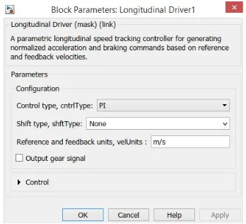
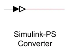
The working of longitudinal driver block is simple. The reference velocity data coming from a drive cycle source is compared to the feedback velocity data coming from the vehicle body block. If the reference velocity is greater than he feedback velocity, an acceleration command will be given as an output to the controlled voltage source. If the reference velocity is lesser than the feedback velocity, a deceleration command will be given as the output to another controlled voltage source instead. For the acceleration and deceleration commands to be given as output signals by using PS-Simulink converter block which is needed to connect the Simulink signals to a physical signal. In this case the input signal is velocity data & this is logic data which we want to convert to a physical signal. i.e. Voltages to a controlled voltage source.
The PS-Simulink block is given below -
Drive Cycle –
A drive cycle is a data set that contains velocity & time data for the purpose of modelling the motion of a vehicle. The drive cycle will be a plot of the velocity against the time & it is made to resemble typical driving conditions that a consumer may experience themselves in. For instance, they can model highway driving situations, driving in urban areas or driving with full power etc., Drive cycles used by automotive companies for various testing procedures such as mileage, pollution tests, & acceleration & top speed tests. These are various different drive cycles that are industry standard. E.g. Urban Dynamometer Driving Schedule (UDDS), FTP75.
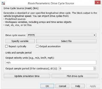
In this EV model a Drive Cycle is used as the reference velocity data for longitudinal driver block to send acceleration or deceleration commands according to the Drive Cycle. There are 3ways of implementing the Drive Cycle. One method is to create or own Drive cycle with a spreadsheet of velocity data in 1 column & time data in another column. Another method is to use signal builder block & create signals that represent the velocities at which the vehicle should travel & durations for which those velocities are to be maintained. The last method is to use industry standard drive cycles which are in-built to the Simulink library. In this case Drive Cycles used are Industry Standard [Wide Open Throttle(WOT)] cycles. It models the situation where the vehicles are made to accelerate at full power & maintained at particular speed & made it to decelerate back at rest. By default, the Drive cycle is set to the FTP75 Drive cycle & this can be modified by opening the block parameters shown below -
The drive cycle block is shown below –
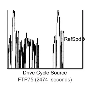
When the ‘WOT’ cycle is chosen, some extra parameters are made available for modification which are shown below –
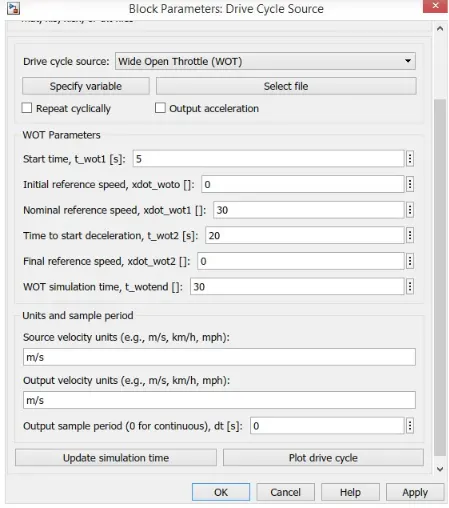
As we can see with the ‘WOT’ Drive cycle, we can modify the start time, time to start deceleration & the entire duration of the Drive cycle. A start time of 5 seconds meaning that the vehicle begin acceleration after 5 seconds of starting simulation. I have used nominal reference speed of 30 m/s & this refers to the maximum speed the vehicle should achieve & set the deceleration to begin at t = 20 Seconds & the whole cycle is set of 30 seconds. The input & output velocity units are both set to m/s.
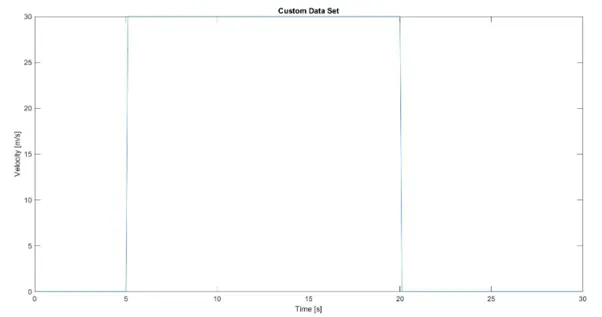
Once the Drive cycle parameters are set the output port of the Drive cycle can be connected to the reference speed port of the longitudinal driver block. If all the parameters have been set as discussed, the connections can be made as shown below –
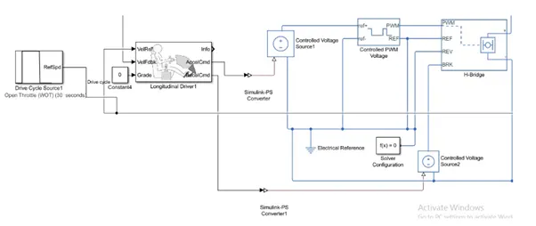
The connection for the vehicle feedback is left open ended for now & will be connected later on. Next we will be connecting the battery of EV.
Battery System –
Battery -
The Battery will be the energy store of the EV & will contain the electrical energy in DC form & provide this energy to the DC motor for it to operate. The Battery block used is a simple one & considers only basic parameters & it’s shown below –
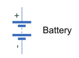
The Battery block parameters are as –
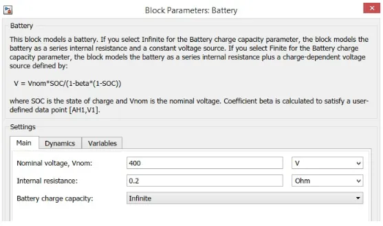
As we can see the Battery block parameters include the nominal voltage, the internal resistance & the Battery Charge Capacity. I have used a nominal voltage of 400 V. the internal resistance of 0.2 Ohms & an infinite battery charge capacity. The nominal voltage is selected so that it’s more than sufficient to supply the voltage to the DC motor & the H-Bridge Blocks.
Controlled Current Source –
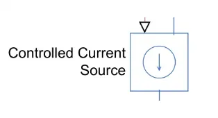
The controlled Current Source block is a part of the Battery system & used in the EV model similar to the controlled voltage source, this block will represent am ideal voltage source that is powerful enough to m maintain the specified current regardless of the voltage across it. The controlled current source block is shown below –
Current Sensor –
The Current Sensor block represents an ideal current sensor & is used to convert the current measured in an electrical circuit to a physical signal that is proportional to the current. This block is used to measure the current between the battery circuit (Controlled Current Source) & the DC motor. The current sensor block is shown below –
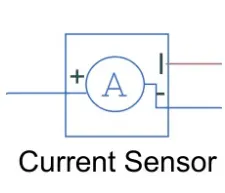
The positive & negative terminals represent the terminals across which the current sensor is inserted in to the circuit. The 3rd port outputs the physical signal & in this model it will send the signal to the controlled current source.
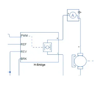
From the image above it is seen that the current sensor is embedded in between the electrical side of the DC motor & the H-Bridge. The current sensor can be connected from its physical signal port to the remaining components in the battery system including an electrical reference block.
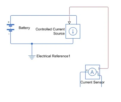
SOC & Current –
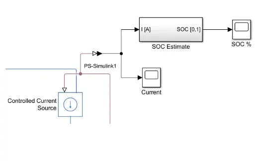
SOC stands for State of Charge & it is the measurement of the available charge in the battery. When the battery is fully charged, it is considered to have 100% charge & conversely 0% charge if fully discharged. In this model measurement of the current & the SOC of the battery as the simulation runs for this the scope block which shows the output signal we wish to measure as plot against time. 2 slopes have been used one for the current & SOC of the battery as the simulation is run. For this, I have used a scope block which shows the output signal we wish to measure as a plot against time. 2 scopes have been used, one for the current & other for the SOC. In order for this to be measured, we need to use ‘PS-Simulink’ converter block. This is because the current signal is physical one & we are measuring it as a logic signal in the Simulink workspace.
The PS-Simulink converter block is shown below –
The scope block is shown below –

SOC Subsystem –
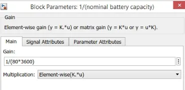
To measure the state of charge of the battery, a subsystem was created of various blocks. The first block is the ‘Rate Transition Block’ & it is used to handle data transfer between different rates & tasks. Next, ‘Gain’ block is used in order to multiply or divide the signal coming from rate transition block. In this case, The Gain block divide the current signal with the Ampere Rating of the battery which has been taken as 80Ah multiplied by 3600 (Seconds in an hour). This s shown in the gain block parameters below –
Then, a ‘Discrete Time Integrator’ block is used to perform discrete integration of the current signal with respect to the time. A constant block is used to represent the initial SOC of the battery. Assuming that the battery is fully charged when performing the simulation, altering the constant block with the value representing 100%. Next a sum block is used to perform addition & subtraction operations. The signal from the ‘Discrete Time Integrator’ block will be subtracted from the constant block representing 100% charge. The components are connected as shown below –
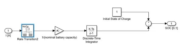
These blocks are then made in to a subsystem called ‘SOC Estimate’ & linked with the battery circuit using the PS-Simulink converter block. A scope block is used at the junction of the PS-Simulink converter block to plot the output signal of the current from the battery. Another scope is used to plot the output signal of the SOC from the SOC subsystem. This is shown in the image below –
Speed Measurement –
In order to measure the speed of the EV model, I needed to use scope block once again. scope block is modified to have 2 input ports where one port takes the output velocity signal from the vehicle subsystem block & another port takes the output signal from the Drive cycle to the reference velocity port on the longitudinal driver block. This has been done so that the scope can show us the plots of the reference velocity & the actual velocity of the vehicle to see how they compare with each other.
Distance Measurement –
Using the scope block & mathematical operator blocks the distance travelled by vehicle according to the drive cycle data. The area under the velocity time graph indicates distance travelled by objects & so in the model. This means that time integration w.r.t. time gives us the distance travelled. So implementation of the integrator block to integrate velocity signal that is output from the subsystem.
The Integrator block is shown below -
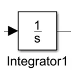
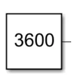
From the Integrator block, ‘Divide Block’ is used along with ‘Constant Block’ having the value of 3600 in order to convert the integrated speed signal which is in kilometres per hour by 3600 & this will give us distance travelled in kilometres.
The constant block with the value 3600 –
The ‘Divide’ block –
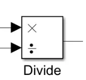
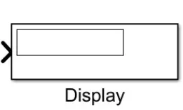
Finally, the ‘Display’ block is used to show the distance travelled as the Simulation Run. The ‘Display’ block is shown below –
If these blocks have been added to the workspace they can be connected as shown below –
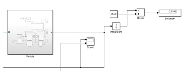
If all these blocks are properly connected we can begin the Simulation of this EV model.
Results –
Running the WOT cycle for the EV model & taking the outputs given from speed, current & SOC scopes. The distance travelled by the vehicle in the drive cycle was also measured using ‘Display’ block. Before running the ‘Stop Time’ for the Simulation was first set to 30 seconds which is the duration of my customized drive cycle.
Speed Scope –
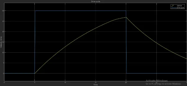
From this scope we can see 2 signals. The blue signal represents he reference signal which originates from the ‘Drive cycle’ data whereas the yellow signal shows the actual velocity of the vehicle. The WOT cycle had been customized so that the vehicle begins acceleration at WOT condition (i.e. Full power) at t = 5 seconds. This is supposed to be maintained till t = 20 seconds when the vehicle is supposed to begin deceleration. From t = 20 seconds to t = 30 seconds the vehicle speed is back to 0 m/s i.e. rest. Because this is a reference signal, all the commands are instantaneous. This is why the increase & decrease in speed is very sudden in fraction of seconds. However, this effect won’t be observed on the actual velocity of the vehicle. This is because in real world conditions, there are more considerations to factor which won’t make it possible for the vehicle to accelerate & decelerate as instantaneously the drive cycle commanded. In the real world the effect of rolling resistance, drag & road inclination makes a different because their presence would cause the vehicle’s motion to deviate from drive cycle commands. Other factors include the vehicle’s inertia & inertia of the transmission system.
Observing the vehicle’s actual velocity, as commanded, the vehicle begins at rest before accelerating under WOT condition at t = 5 seconds. This acceleration is maintained till t = 20 seconds as the drive cycle commanded. At t = 20 seconds the vehicle begins to decelerate gradually till t = 30 seconds with the vehicle finishes with the velocity approximately 7 m/s. as mentioned earlier the actual velocity couldn’t match the drive cycle commands perfectly & this is due to several factors which were discussed above. In my model, I have not modelled the road inclination but I have used a wind velocity of 5 m/s. comparing the effects of the wind resistance on the top speed of the vehicle to when there was no wind resistance. The effect was very insignificant, only affecting the top speed by 0.5m/s. however, the vehicle’s velocity has been accelerated & decelerated as the drive cycle commanded. Obviously the model is limited to the simulation time allotted. So if a longer simulation time is used, the vehicle may reach top higher speed & may even decelerate back to rest.
Current Scope –
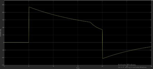
The current scope shows how the current is flowing from the battery to the motor varies with the drive cycle time. As we can see initially the current flowing through the circuit is 0A & this corresponds to the drive cycle commanding the vehicle to be at rest for this time period. At t = 5 seconds, when the vehicle is commanded to accelerate, the current instantaneously increases to a maximum current of 235.8 A. the current must have decreased over time because as the vehicle was accelerating, it required lesser current from the battery to continue accelerating. The highest current is always required when accelerating from the rest due to the inertia of the vehicle, But the vehicle is already in motion, it requires significantly lesser energy to continue accelerating. From t = 17.5 seconds to t = 20 seconds, the current flowing from the battery decreases more rapidly to 85.6 A. this is because at this time the acceleration of the vehicle began to level off that means increase in speed in those 2.5 seconds was lesser than the increase from t = 5 seconds to t = 17.5 seconds.
After t = 20 seconds the vehicle decelerates causing the current to drop instantaneously to the negative axis to a value of -107.4 A. this is now a negative current flowing due to regenerative braking. When the vehicle decelerates, the throttle is no longer applied & so the K.E. from the motion is converted to electrical energy fed back to the battery of the EV. This reverse current flow is what causes the negative current measurement. From t = 20 seconds, the deceleration continues however the current flowing through battery decreases in magnitude. This is because at t = 20 seconds, the vehicle had reached its top speed & hence its maximum K.E. so at that point there was more K.E. which could be converted to electrical energy for regenerative braking. However, as the vehicle decelerates there was lesser energy available for regenerative braking causing the magnitude of the current to decrease. The polarity of the current hence move towards positive direction because regenerative breaking happens lesser & lesser until the vehicle comes at rest. At t = 30 seconds the vehicle is still decelerating and finished with current measurement -27.9 A showing that regenerative braking is still occurring.
SOC scope –
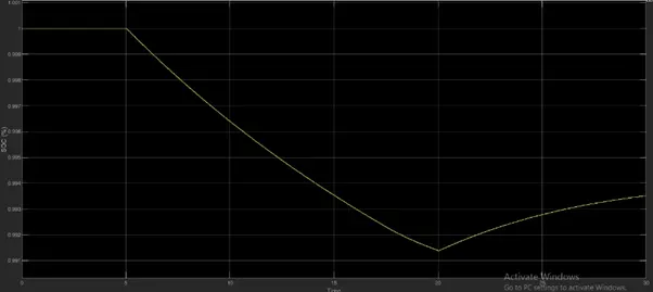
The SOC scope shows how the state of charge of the battery varies over the drive cycle time. The battery was modelled to begin with an SOC of 1 (100%) & so when the simulation begins the SOC is at 1 until t = 5 seconds. This is because the drive cycle commands the vehicle to be rest for that duration & so no charge occurs from the battery. At t = 5 seconds, the vehicle commanded to accelerate under the WOT condition & so the SOC of the battery decreases. Because the vehicle is accelerating at full power the SOC falls from 1 but the rate of charge decreases over the acceleration period eventually settling at minimum SOC of 0.9914 at t = 20 seconds. This corresponds to the current flow from the battery because as the vehicle accelerates, lesser energy is demanded to increase the speed. As mentioned before, the greatest discharge occurs when the greatest current flows from the battery and this is during the initial acceleration period. As the vehicle speed increases the acceleration decreases causing the current & hence the rate of discharge to decrease but in a mild fashion. At t = 20 seconds the vehicle is commanded to decelerate & so the vehicle velocity decreases. This results in regenerative braking to occur which causes a negative flow of current back to the battery. Because this effect charges the battery, the SOC of the battery increases during deceleration period. The SOC increases very gently from 0.9914 to 0.9935 & this is because it gets charged by the regenerative effect. The negative flow of the current corresponds to the increase in the SOC of the battery. Since the vehicle is commanded to decelerate until t = 30 seconds the vehicle speed decreases but doesn’t reach 0 m/s, so the vehicle is under regenerative braking for the entire speed after t = 20 seconds.
Distance Measurement –
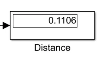
From the image above we can see that the display block has measured the distance travelled by the EV model for the customized WOT cycle to be 0.1106 KM. this measurement seems appropriate & correct since WOT cycle duration is very short in duration & only requires acceleration for half of the drive cycle’s overall duration. The area under the velocity time graph tells us the displacement of an object. From looking at the speed scope a rough calculation indicates that this distance measurement is correct.
Displacement is defined as distance in a given direction & it is a vector quantity means it has both size & direction. So if the velocity data in a drive cycle was negative this would indicate that the vehicle is moving in the reverse direction & this would correspond to negative displacement. The display block would indicate the same if the velocities in the drive cycle data were of that nature.
Conclusion –
In conclusion the EV model has been created with the necessary block components using the Simulink software & the model has been simulated for a customized WOT Drive cycle. The simulation has produced results of the velocity of the vehicle, current flowing from the battery & the SOC of the battery as well as the distance travelled by EV. Since the EV model was parameterized to simulate averaged voltage pulses in the H-Bridge & controlled PWM voltage blocks to be fed into the DC motor, the simulation was run very quickly within a matter of seconds. The EV model was able to follow the commands given by the reference velocities from the drive cycle data, although it could have followed the reference signals more closely. The discrepancy between the reference velocity & the actual velocity of the vehicle may be attributed to a variety of factors e.g. Vehicle inertia, Transmission system, Transmission inertia. If the vehicle model is designed in such a way as to improve upon those factors, the model would follow the reference signals more closely & would improve the performance characteristics as well. The distance travelled by EV model 0.1106 KM & seems to be appropriate value based on the WOT drive cycle used.
The SOC of the battery of the model used in EV model didn’t get discharged in the way it had expected. This could be because the drive cycle commands didn’t push the EV model to limits or it could be due to the fact that the battery model was very efficient & was suitable for driving application. This model has some actual features of EV such as regenerative braking & this was evident in the current time & SOC time graphs whenever the EV decelerated. If the duration of the WOT drive cycle was modified to be longer the EV could exhibit its true performance characteristics. For e.g. the EV could achieve its top speed & it may also have been possible to see the time it takes for the vehicle to decelerate from that top speed & hence time taken for the acceleration e.g. 0 to 60 KMPH.
After some Final Modifications the EV model will look like -
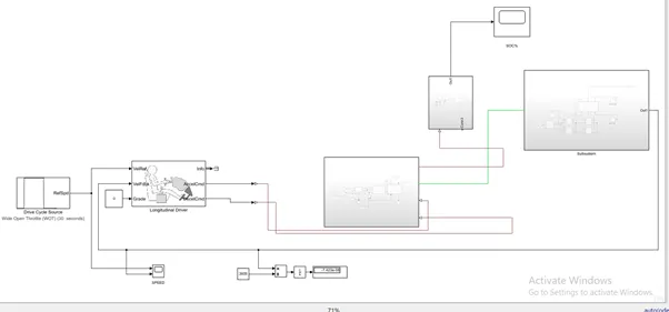
Simulink Model file -
https://drive.google.com/file/d/1eucERi_OAOxGvTz2-qfR9_kY3S7ieSZU/view?usp=sharing