Design of an Electric Vehicle using MATLAB and Simulink
Design of an Electric Vehicle
Introduction
In the recent years, many existing automobile manufacturers and new dedicated companies have put a remarkable effort in transforming the conventional vehicle into an Electric Vehicle that provides green and reliable solutions. In terms of market share, EV demand is rising. It has started replacing conventional vehicle In USA, Europe and Asia. With revolutionized perspective and competitive price (Entry range), EV is a smart choice for any end user, however, an extra effort is required to enhance the range of autonomy and vary applications.
This project formulates the state-of-the-art on electric vehicles, power management including hardware and software levels explanation, charging techniques and standards.
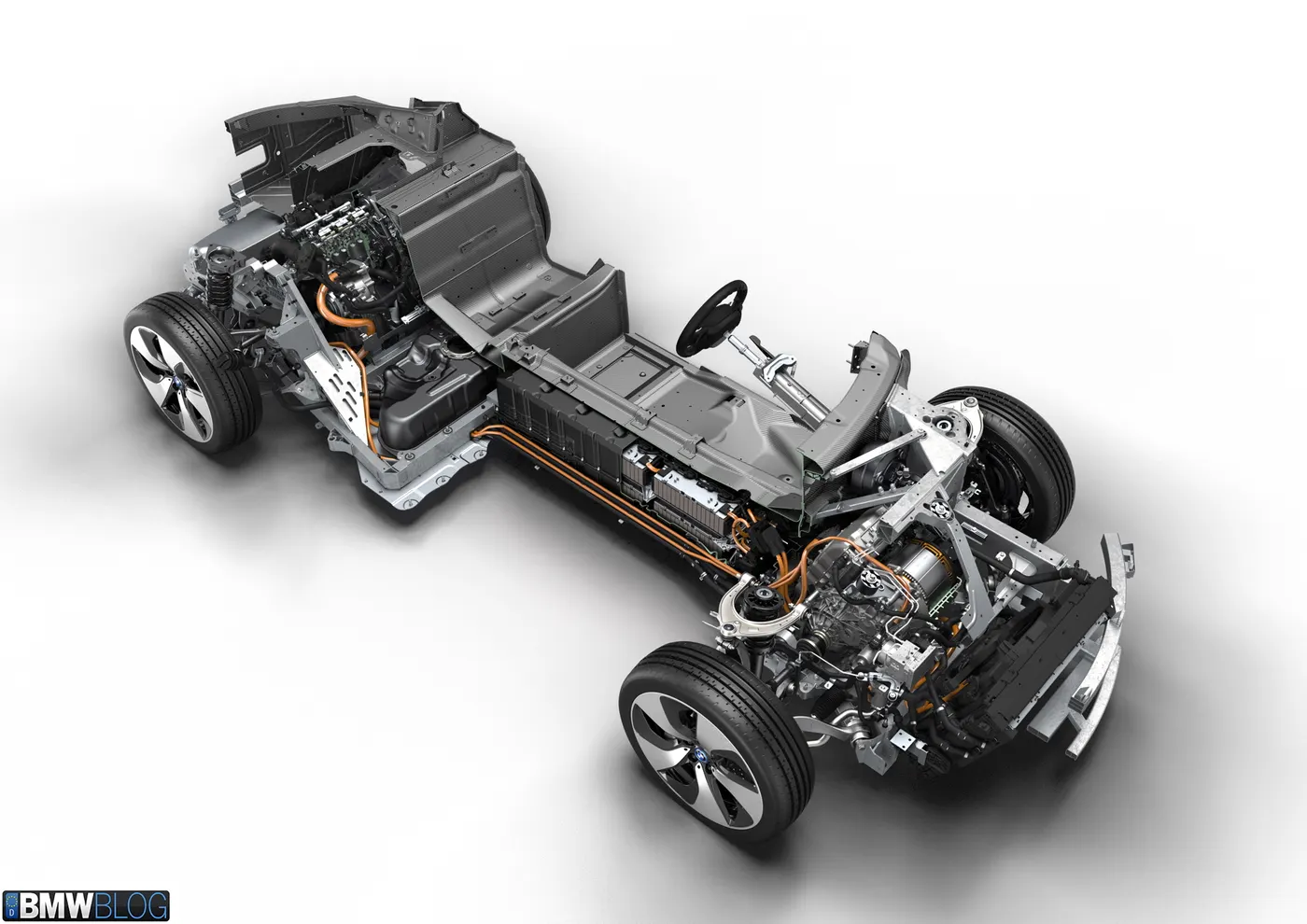
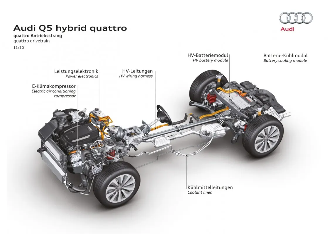
The motor converts electrical energy into kinetic energy that moves the wheels. The advantage of using the motor instead of an engine is numerous: first, the noise and the vibration we typically associate with cars are minimized. Many passengers riding EVs for the first time are surprised by just how quiet and comfortable the ride feels. Moreover, the EV powertrain is smaller than the engine, thus providing lots of additional space for efficient vehicle design―like expanded cabin space or storage.
The motor is also in part an electric generator―it converts the kinetic energy generated while in neutral gear(e.g. while the car is going downhill) into electric energy saved to the battery. The same energy-saving idea applies when the car is reducing its speed, culminating in the so-called “regenerative braking system.” Some of the Hyundai Motor Group’s EVs are equipped with a mechanism that can control the levels of regenerative braking via paddle shifters on the steering wheel, which not only improves the fuel economy but also adds an interesting and fun element to driving.
Reducer
The reducer is a kind of transmission in that it serves to effectively convey the motor’s power to the wheel. But it carries the special name―reducer―for a reason: the motor has a far higher RPM than that of an internal combustion engine, so whereas transmissions change the engine RPM to match the driving circumstance, the reducer must always reduce the RPM to an appropriate level. With the reduced RPM, the EV powertrain can take advantage of the resulting higher torque.
The battery stores electrical energy and is the equivalent of a fuel tank in an internal combustion engine. The maximum driving distance of an EV is often determined by the battery capacity―the higher the capacity, the higher the driving distance. In that light, increasing the capacity may seem an obvious choice, since high driving distance reduces the annoying need for frequent stops at charging stations. But the choice actually isn’t so obvious, because the battery’s size and weight also have large implications on vehicle performance. The larger and heavier battery takes away from cabin/storage space and worsens the energy efficiency and fuel economy. The best way to optimize performance, then, is to maximize the battery’s energy density―that is, having a small, lightweight battery that stores as much electric energy as possible.
Thanks to the recent advancements in battery technology, the more recent EVs boast significant upgrades over older models in terms of battery density and driving distance. The Kia Soul Booster EV, for example, is equipped with a 64kWh lithium-ion battery that lasts for the max distance of 386 km(according to Korean certification standards). The battery life also saw significant improvements: assuming a normal pattern of usage, the Soul Booster EV’s battery can last through the entire life cycle of the vehicle. To explain in greater detail, understand first that lithium-ion batteries on EVs show battery life that varies with the charging pattern. If the charging pattern is such that the entire battery is exhausted and recharged to full, the battery can be used for 1,000 charges; if the battery is used to half(50%) and recharged, 5,000 charges; if one-fifth of the battery is used(20%) and recharged, 8,000 charges. Meaning, if the Soul Booster EV is driven for 77 kilometers a day(equivalent to the 20% of the max driving distance) and recharged every night, the battery can last for 8,000 days(22 years).
- Lithium-Ion Batteries: This battery technology gives extra performance and range. However, it also carries the highest price tag. Lithium-ion batteries are lighter than Lead acid and Nickel metal. These are also the batteries used in digital cameras and smartphones.
- Lead Acid Batteries: This battery technology is the most popular. It is also the cheapest among the battery technologies. What’s good about it is it’s 97% recyclable.
- Nickel Metal Hydride Batteries: This battery technology provides higher output and better performance but it costs much more than lead-acid batteries
Battery Management System(BMS)
The Battery Management System(BMS) manages the battery’s many cells so that they can operate as if they are a single entity. The EV’s battery consists of as little as tens to as many as thousands of mini-cells, and each cell needs to be in a similar condition to the others in order to optimize the battery’s durability and performance.
Most often, the BMS is built into the battery’s body, though sometimes it is incorporated into the Electric Power Control Unit(EPCU). The BMS mainly oversees the cell’s charge/discharge status, but when it sees a malfunctioning cell, it automatically adjusts the power status of the cell(on/off) through a relay mechanism(the conditional mechanism for opening/closing other circuits).
In lower temperatures, the battery sees a decrease in both charging capacity and speed. The battery heater exists to keep the battery within the ideal temperature range, preventing seasonal performance decreases and maintaining the max driving distance. The system functions while charging as well, ensuring the efficiency of the charge.
On-board Charger(OBC)
The On-board Charger(OBC) is used to convert Alternating Current(AC) from slow chargers or portable chargers used on home outlets into Direct Current(DC). This may make the OBC look similar to the traditional inverter, but they differ crucially in function; the OBC is for charging, and the inverter is for acceleration/deceleration. Incidentally, the OBC is not needed in fast-charging, since fast chargers already supply the electricity in direct current.
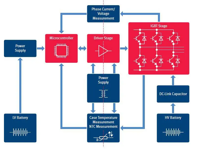
The Electric Power Control Unit(EPCU) is an efficient integration of nearly all devices that control the flow of the electric power in the vehicle. It consists of the inverter, the Low voltage DC-DC Converter(LDC), and the Vehicle Control Unit(VCU).
1. Inverter
The inverter converts the battery’s DC into AC, which then is used to control the motor speed. The device is responsible for executing acceleration and deceleration, so it serves a crucial part in maximizing the EV’s drivability.
2. Low voltage DC-DC Converter
The LDC converts the high voltage electricity from the EV’s high-voltage battery into low-voltage(12V) and supplies it to the vehicle’s various electronic systems. All electronic systems in the EV use electricity in low voltage, so the high voltage in the battery must be converted first to be useful for these systems.
3. Vehicle Control Unit
As the control tower of all electric power control systems in the vehicle, The VCU is arguably the most important component of the EPCU. It oversees nearly all the vehicle’s power control mechanisms, including the motor control, regenerative braking control, A/C load management, and power supply for the electronic systems.
Now coming to my project,
To design and simulate Electric Vehicle using MATLAB and Simulink
Requirments:
Total weight of vehicle = 1200kg
Top speed = 100kmph
Total distance travelled in a single charge = 250 kms
Area of vehicle = 2.65 `m^2`
Wheel size = 0.3 m
Efficiency of motor `eta` = 90%
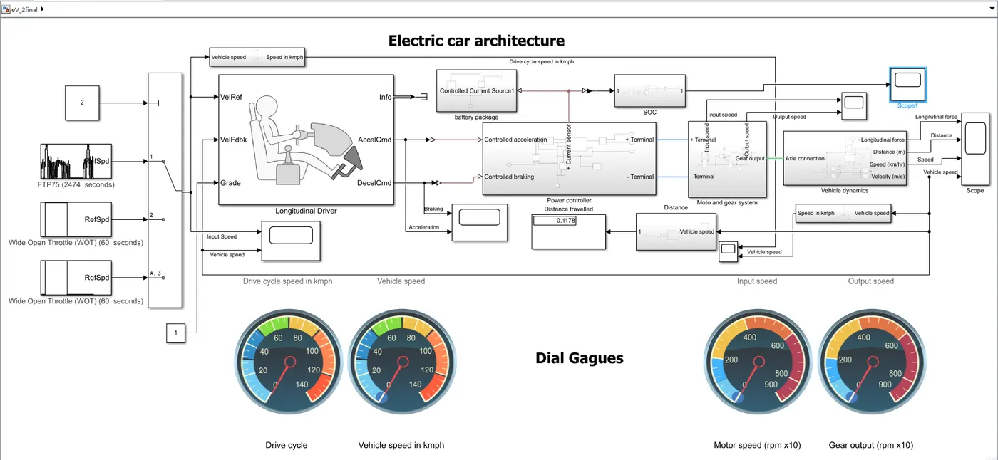
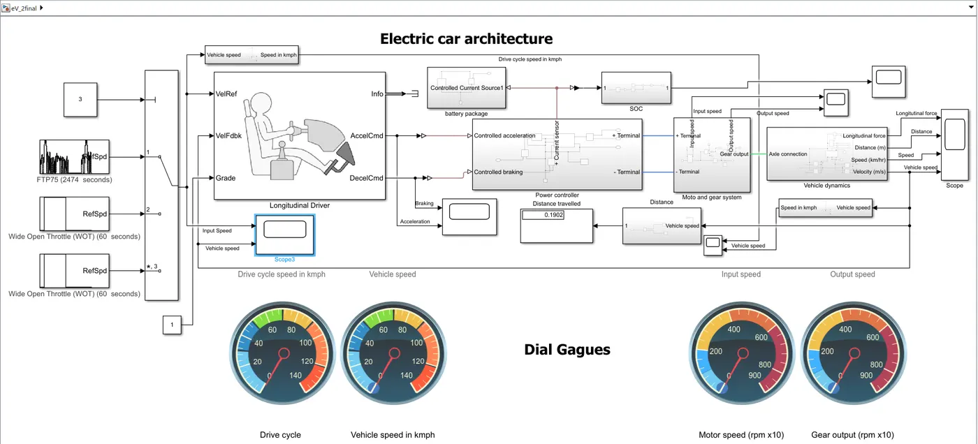
Simulink Model
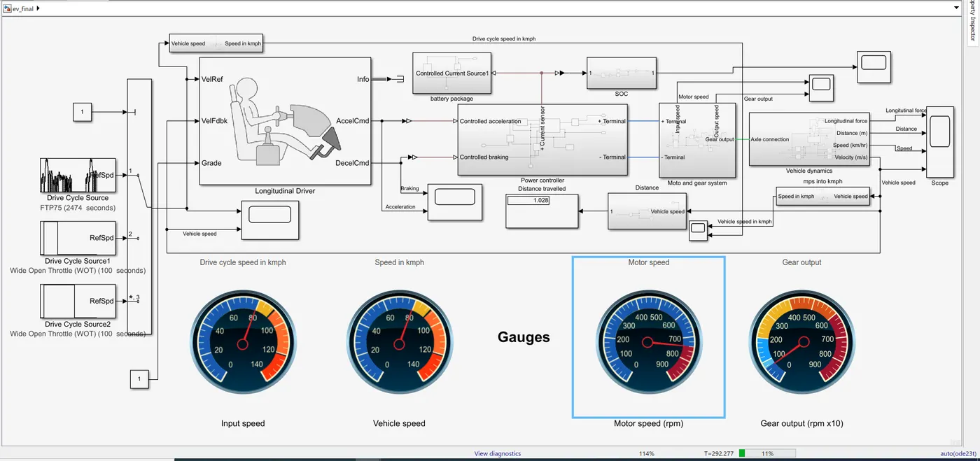
System level configuration and their Parameters
1. Vehicle Dynamics
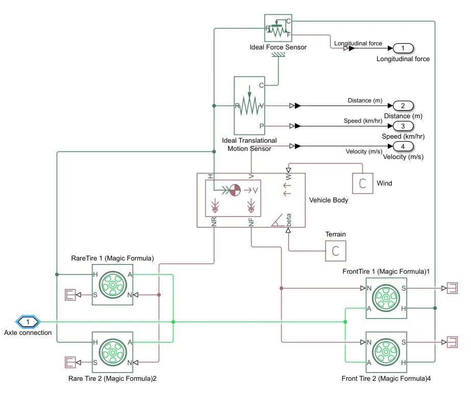
The vehicle dynamics subsystem represents the body of vehicle and physical environment, where various blocks like Tire(magic formula), Vehicle body, PS terminator, PS constant, Ideal force sensor and Ideal translational motion sensor is used.
Tire(Magic formula)
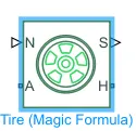
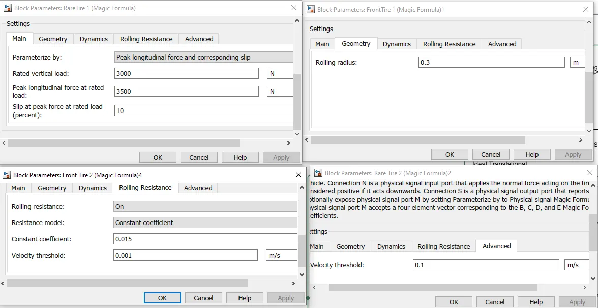
Connection A is the mechanical rotational conserving port for the wheel axle. Connection H is the mechanical translational conserving port for the wheel hub through which the thrust developed by the tire is applied to the vehicle. Connection N is a physical signal input port that applies the normal force acting on the tire. The force is considered positive if it acts downwards. Connection S is a physical signal output port that reports the tire slip. Optionally expose physical signal port M by setting Parameterize by to Physical signal Magic Formula coefficients. Physical signal port M accepts a four element vector corresponding to the B, C, D, and E Magic Formula coefficients.
A - Axles
H - Hub
N - Normal force
S - Slip
Vehicle body
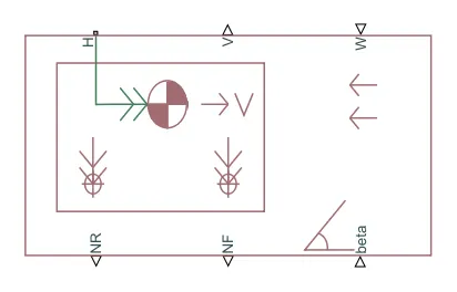
Represents a two-axle vehicle body in longitudinal motion. The block accounts for body mass, aerodynamic drag, road incline, and weight distribution between axles due to acceleration and road profile. The vehicle can have the same or a different number of wheels on each axle. Optionally include pitch and suspension dynamics or additional variable mass and inertia. The vehicle does not move vertically relative to the ground.
Connection H is the mechanical translational conserving port associated with the horizontal motion of the vehicle body. The resulting traction motion developed by tires should be connected to this port. Connections V, NF, and NR are physical signal output ports for vehicle velocity and front and rear normal wheel forces, respectively. Wheel forces are considered positive if acting downwards. Connections W and beta are physical signal input ports corresponding to headwind speed and road inclination angle, respectively. If variable mass is modeled, the physical signal input ports CG and M are exposed. CG accepts a two- element vector representing the x and y distance offsets from vehicle CG to additional load mass CG. M represents the additional mass. If both variable mass and pitch dynamics are included, the physical signal port J accepts the inertia of the additional mass about its own CG.
H - Hub
V - Velocity of vehicle
NR - Normal force at rare tyers
NF - Normal force at front tyres
W - Wind velocity
beta - Road inclination angle
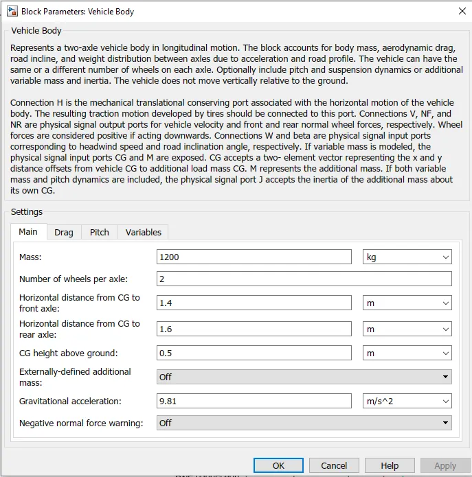
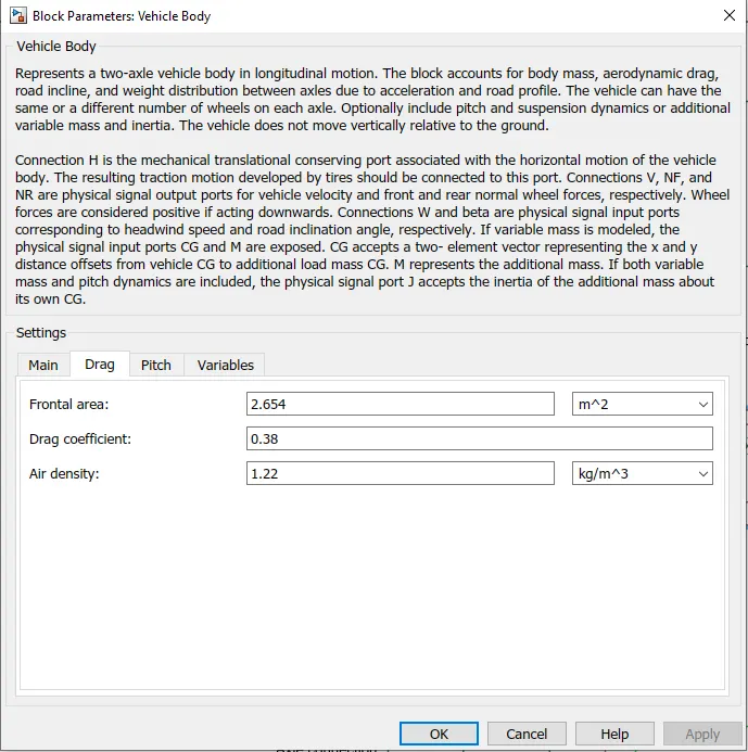
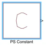
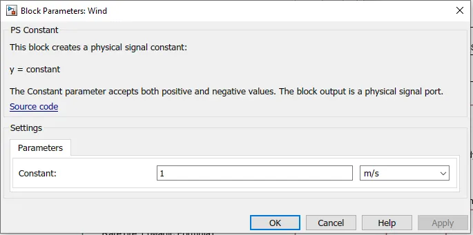
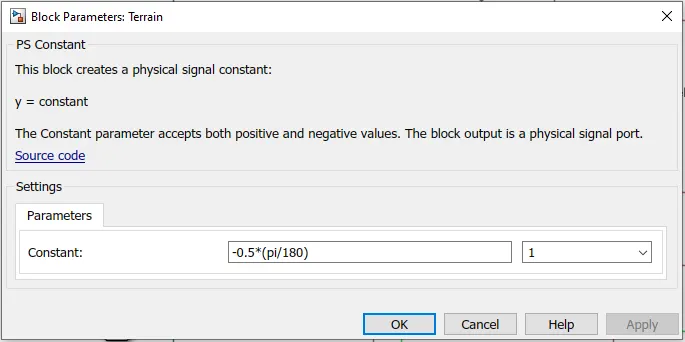
The wind speed and Terrain values are given by using PS Constant block to the vehicle body
2. Motor and Gear system
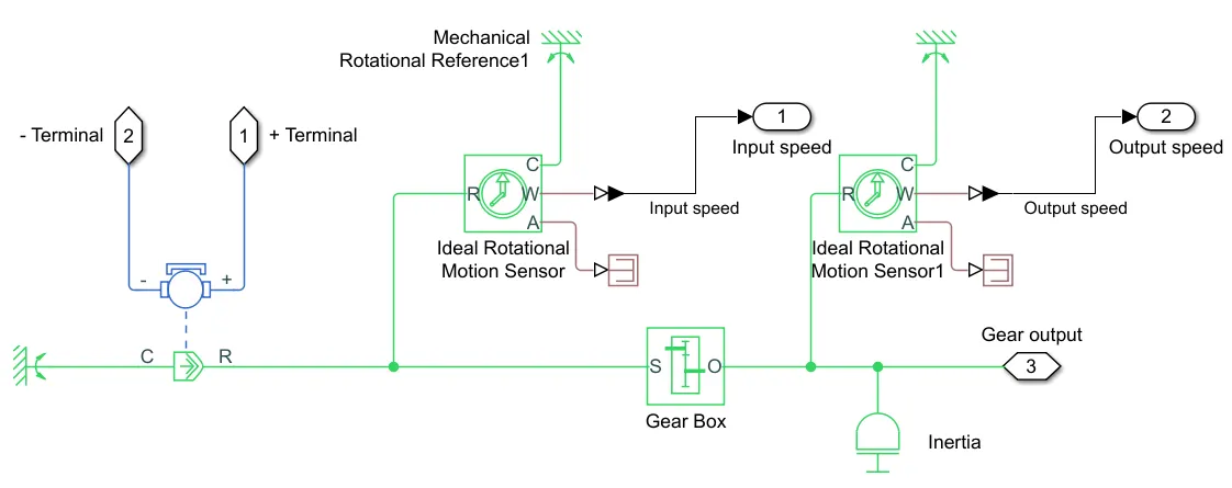
In this subsystem I have taken DC motor, gear box, Inertia block, rotational sensors and mechanical rotational reference.
The motor drives the gear box which inturn it's outup is connected to the wheel axles of the vehicle, here the model is 4 wheel drive as the power is supplied to all wheels as shown in vehicle dynamics subsystem
DC Motor
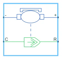
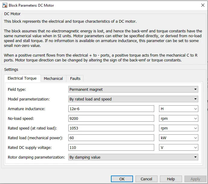
The block assumes that no electromagnetic energy is lost, and hence the back-emf and torque constants have the same numerical value when in SI units. Motor parameters can either be specified directly, or derived from no-load speed and stall torque. If no information is available on armature inductance, this parameter can be set to some small non-zero value.
When a positive current flows from the electrical + to - ports, a positive torque acts from the mechanical C to R ports. Motor torque direction can be changed by altering the sign of the back-emf or torque constants.
Gear Box
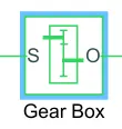
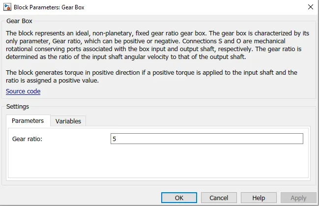
The block generates torque in positive direction if a positive torque is applied to the input shaft and the ratio is assigned a positive value.
Ideal rotational sensors are used to meassure the output of DC motor and Gear box
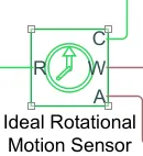
The physical signal ports W and A report the angular velocity and angular displacement, respectively, of port R relative to port C. The measurement is positive when the motion at R is greater than the motion at C.
The shafts has their own moment of inertia and this is provided by Inertia block
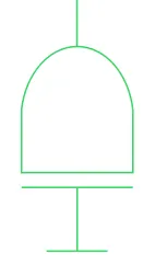
The block has one or two mechanical rotational conserving ports. The difference is purely graphical, as the ports are rigidly linked. The block positive direction is from its port to the reference point. This means that the inertia torque is positive if the inertia is accelerated in the positive direction.
3. Power Controller
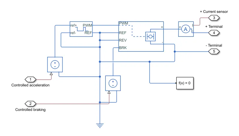
This subsystem manages the power requirments of the EV using H-bridge contorller.
This subsystem includes mainly H-bridge, Controlled PWm voltage generator and Voltage and current sensors
H-Bridge
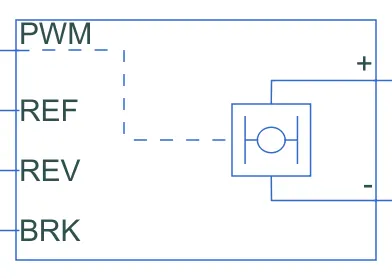
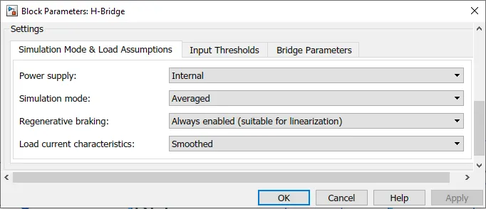
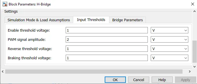
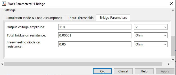
This block represents an H-bridge motor drive. The block can be driven by the Controlled PWM Voltage block in PWM or Averaged mode. In PWM mode, the motor is powered if the PWM port voltage is above the Enable threshold voltage. In Averaged mode, the PWM port voltage divided by the PWM signal amplitude parameter defines the ratio of the on-time to the PWM period. Using this ratio and assumptions about the load, the block applies an average voltage to the load that achieves the correct average load current. The Simulation mode parameter value must be the same for the Controlled PWM Voltage and H-Bridge blocks. If the REV port voltage is greater than the Reverse threshold voltage, then the output voltage polarity is reversed. If the BRK port voltage is greater than the Braking threshold voltage, then the output terminals are short circuited via one bridge arm in series with the parallel combination of a second bridge arm and a freewheeling diode. Voltages at ports PWM, REV and BRK are defined relative to the REF port. If exposing the power supply connections, the block only supports PWM mode.
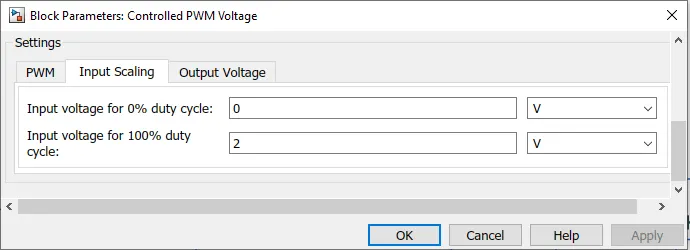
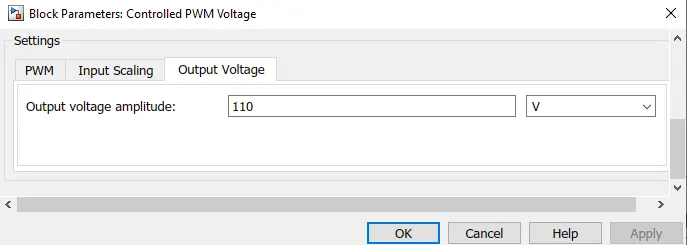
Controlled PWM Voltage

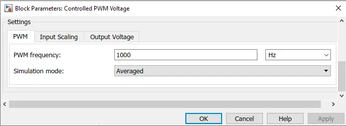
This block creates a Pulse-Width Modulated (PWM) voltage across the PWM and REF ports. The output voltage is zero when the pulse is low, and is equal to the Output voltage amplitude parameter when high. Duty cycle is set by the input value. Right-click the block and select Simscape->Block choices to switch between electrical +ref/-ref ports and PS input u to specify the input value. At time zero, the pulse is initialized as high unless the duty cycle is set to zero or the Pulse delay time is greater than zero. The Simulation mode can be set to PWM or Averaged. In PWM mode, the output is a PWM signal. In Averaged mode, the output is constant with value equal to the averaged PWM signal.
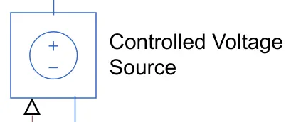
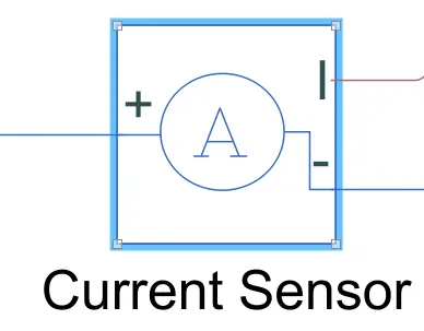
Constant voltage source and current sensors are used to meassure and supply reqiured voltage and current
4. Battery Package
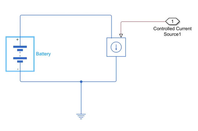
This subsystem powers the EV, contains DC power supply by a battery
Battery
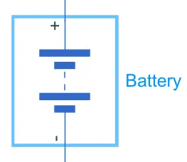
This block models a battery. If you select Infinite for the Battery charge capacity parameter, the block models the battery as a series internal resistance and a constant voltage source. If you select Finite for the Battery charge capacity parameter, the block models the battery as a series internal resistance plus a charge-dependent voltage source defined by:
V = Vnom*SOC/(1-beta*(1-SOC))
where SOC is the state of charge and Vnom is the nominal voltage. Coefficient beta is calculated to satisfy a user-defined data point [AH1,V1].
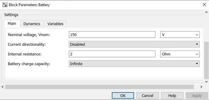
Here the battery nominal voltage is set higer than rated motor voltage to provide more than sufficient and to power other electroincs installed in the vechile.
5. State of Charge (SOC)
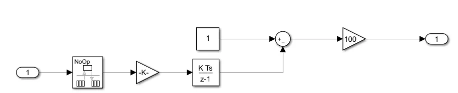
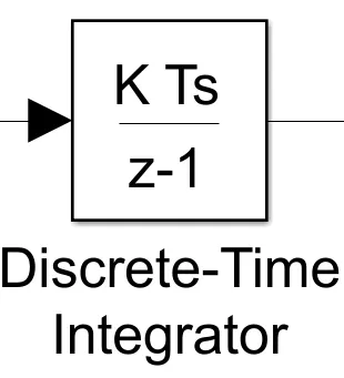
Handle data transfer between different rates and tasks.
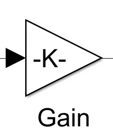
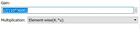
Element-wise gain (y = K.*u) or matrix gain (y = K*u or y = u*K).
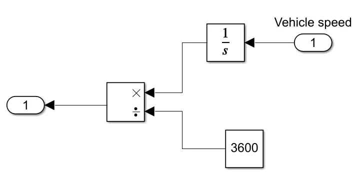
6. Longitudinal Driver
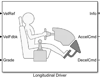
A parametric longitudinal speed tracking controller for generating normalized acceleration and braking commands based on reference and feedback velocities. Use the external actions to input signals that can disable, hold, or override the closed-loop commands determined by the block. The block uses this priority for the input commands: disable, hold, override.
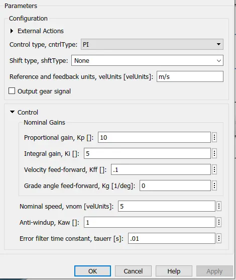
To calculate Distance travelled
Finally drive cycles
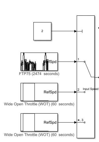
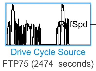
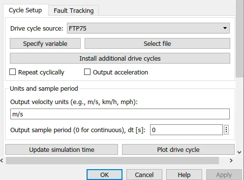
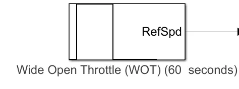
Generates a standard or user-specified longitudinal drive cycle. The block output is the vehicle longitudinal speed.
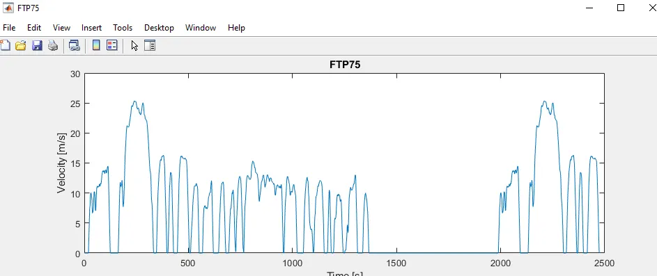
FTP75 drive cycle
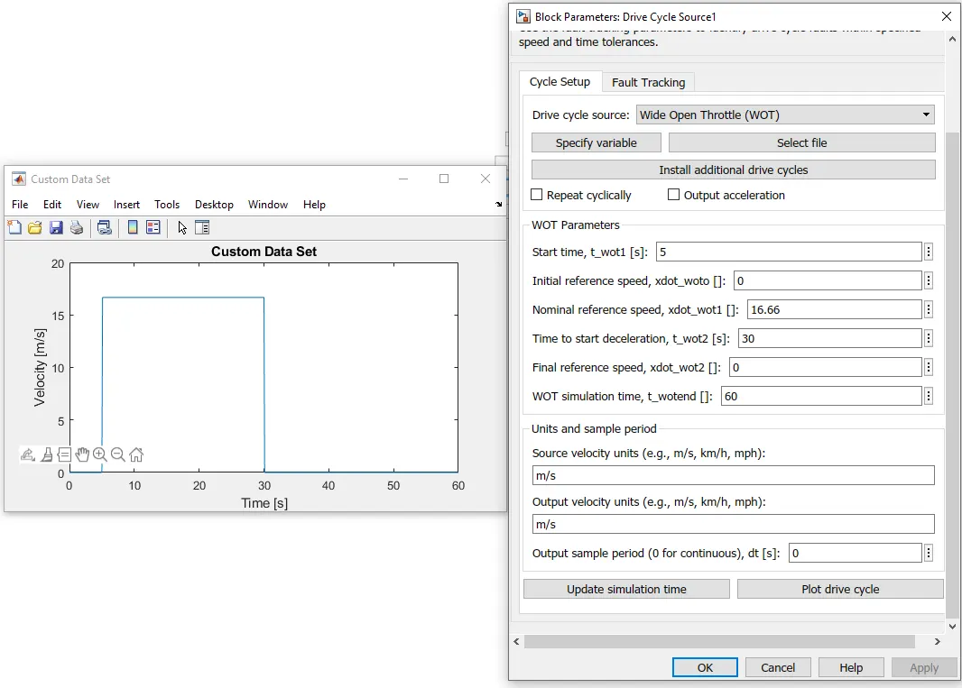
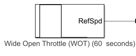
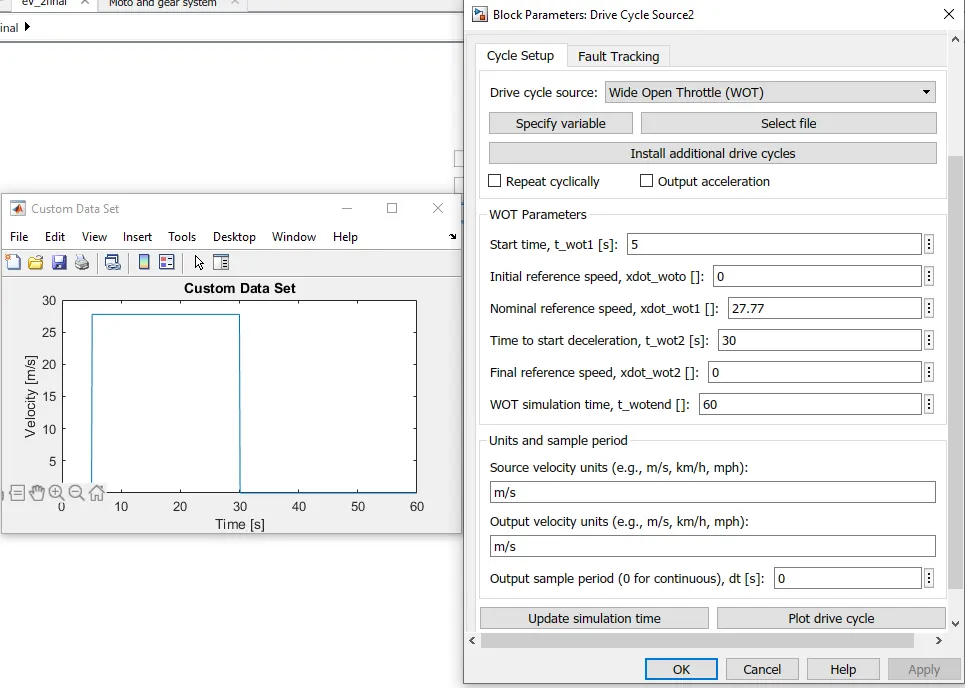
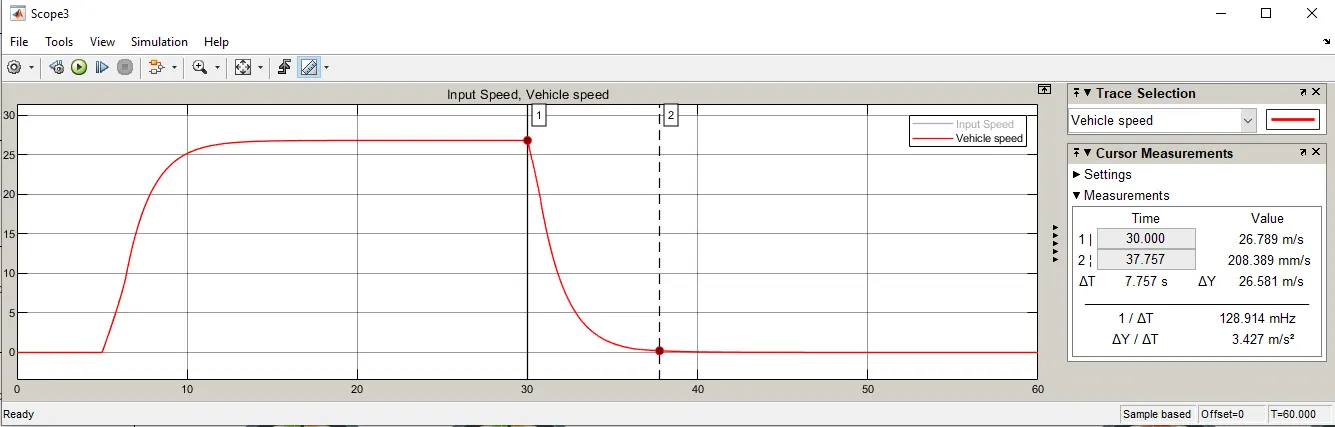
WOT 0-60kmph
WOT 0-100kmph
Simulations results:
1. For FTP75 Drive cycle 2474secs
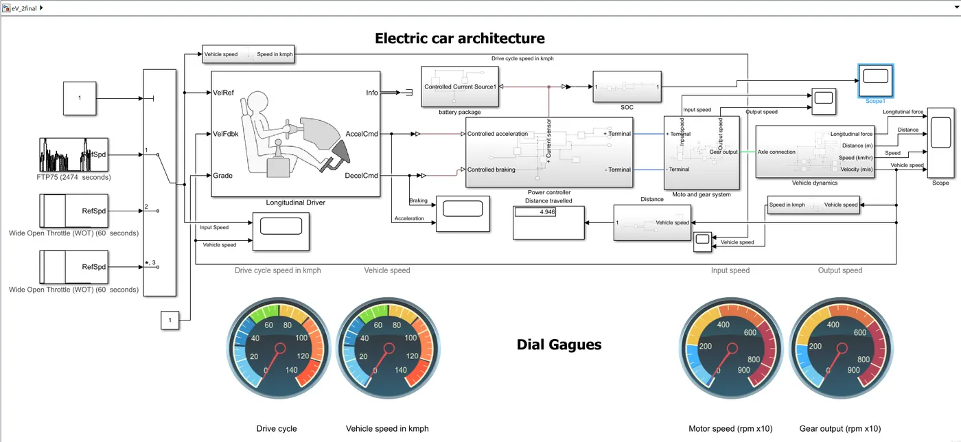
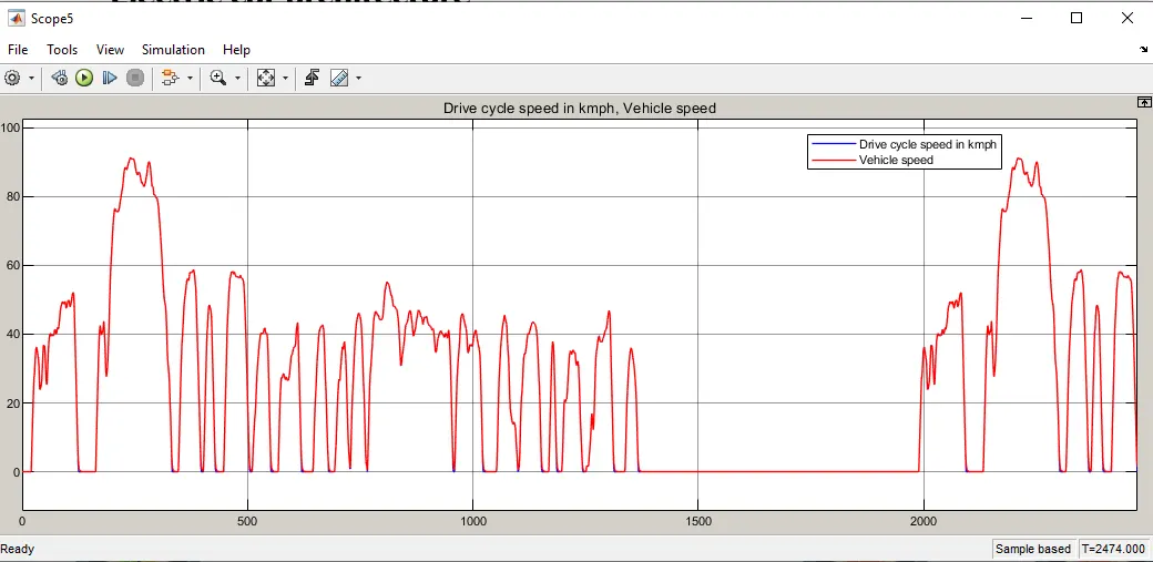
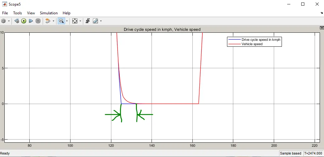
From above two plots we can observe that the vehicle speed is keepin up with the drive cycle input, and while decelerating there is a delay because of while braking the vehicle dose not come to rest immidetly as there will be moment of inhertia of vehicle.
Total distance travelled = 4.964km
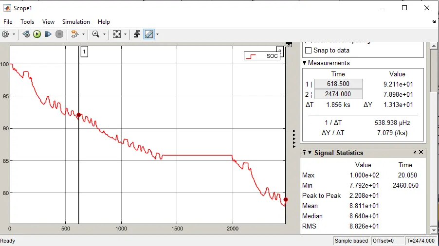
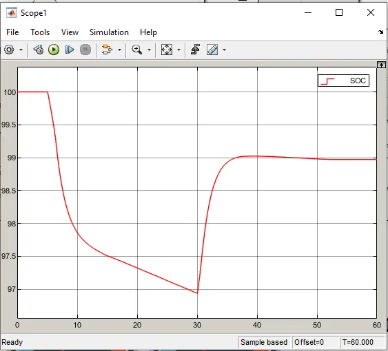
The SOC of vehicle after running for 2474secs is 78% ie 22% of battery is comsumed durimg the run.
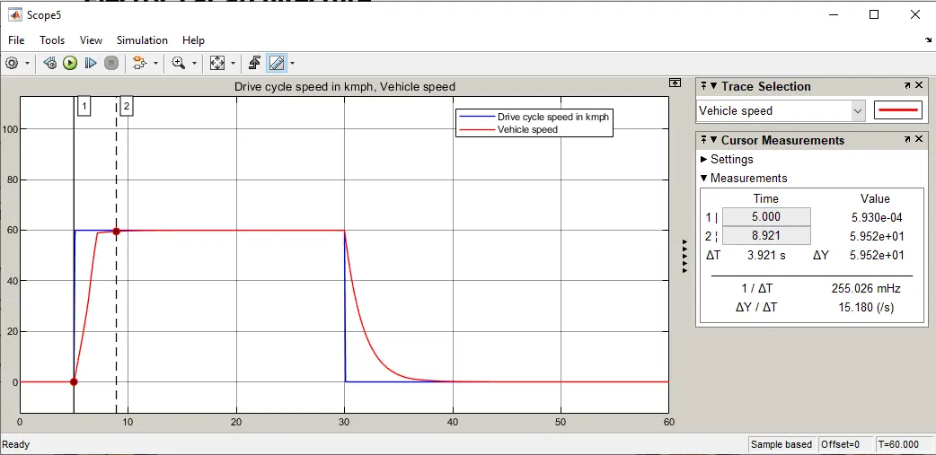
2. For WOT 0-60kmph
Total distance covered = 0.117km
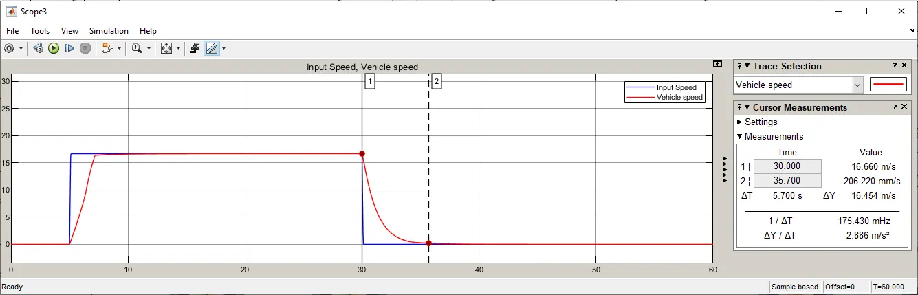
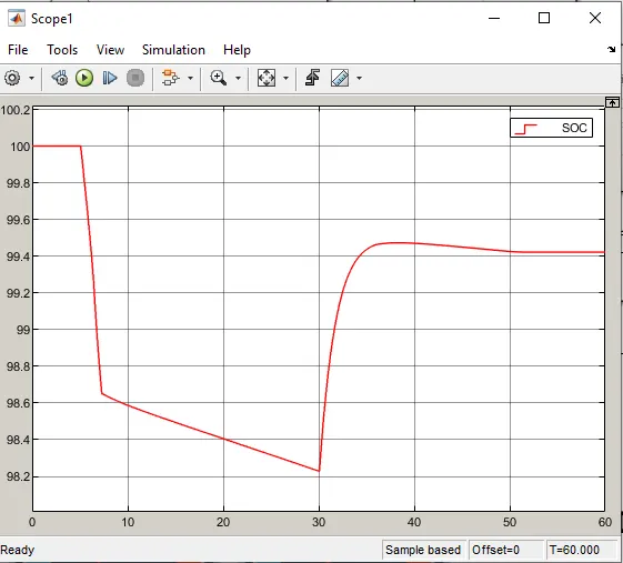
3. For WOT 0-100kmph
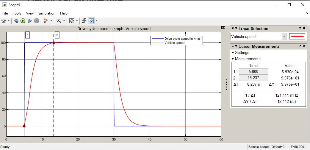
Total distance covered = 0.19
km
| Parameters | WOT 0-60kmph | WOT 0-100kmph |
| Acceleration test | 0 to 60kmph at 3.9 sec | 0 to 100kmph at 8.2 sec |
| Braking test | 60 to 0kmph at 5.7 sec | 100 to 0kmph at 7.7 sec |
| SOC at the end of the run | 99.4% | 99.4% |
Observations and conclusions
An EV is designed, through Simulink using necessary blocks and the model has been simulated for FTP75 drive cycle and Speed test using WOT for 0 to 60kmph and 0 to 100kmph.
My motor is powerfull enough to drive 1200kg vehicle and it easily reached my calculated top speed and the range of my vehicle is 250kms at single charge.
My battery pack deliverys enough voltage to drive the motor and I also observed that the battery is more efficient, just 3% of battery is consumed to reach the top speed of 100kmph.
In order to say a vehicle to be well designed one, it should have less drag force, i.e, it has tobe designed aerodymaically, as speed is increased by two times then the drag force will be increased by four times.
This is a major disadvantage for aerospace and automobile sectors as the drag force increases with increasing speed, fuel and battery consumption will be high to achieve desired speed and to overcome the drag force acting on them. This could affect the efficiency of the vehicle. Hence the design has to be done with respect to reducing the frontal cross-sectional area by adopting cutting edge technology.
Different fluid medium offers various drag co-efficient to the object, if the drag co-efficient is less then the resistant force or drag force acting on the body is lower and the body is said to be aerodynamically or hydrodynamically well designed.
- Sk GamerCan you please share your MATLAB model for this project.
- Swapnil SarwadeI have problems in SOC modelling . Can u send me this stimulation.