Final Project: Design of an Electric Vehicle
Create a MATLAB model of electric car which uses a battery and a DC motor. Choose suitable blocks from Powertrain block set. Prepare a report about your model including following:
Objectives:
1. System level configurations
2. Model parameters
3. Results
4. Conclusion
Objectives:
- To create a MATLAB Model of an Electri Car by using a Battery and DC Motor.
- To check Out performance parameters: Speed, SOC, Current, etc. accordingly to the Drive Cycle.
- To Simulate the results.
- System Level Configuration:
Firstly, let us know about what is an Electric Vehicles and the different components and their functions in an EV.
- Electric Vehicle (EV):
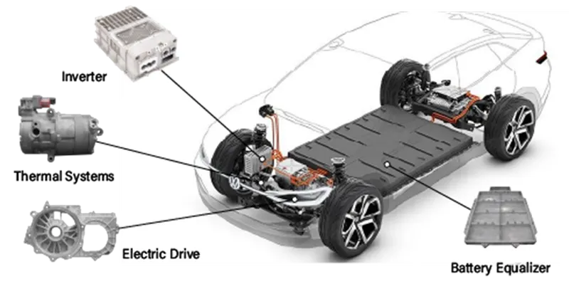
An Electric Vehicle (EV) is a vehicle that uses one or more electric motors or traction motors for propulsion. An electric vehicle may be powered through a collector system by electricity from off-vehicle sources or may be self-contained with a battery, solar panels, fuel cells or an electric generator to convert fuel to electricity. EVs include, but are not limited to, road and rail vehicles, surface and underwater vessels, electric aircraft and electric spacecraft.
EVs first came into existence in the mid-19th century, when electricity was among the preferred methods for motor vehicle propulsion, providing a level of comfort and ease of operation that could not be achieved by the gasoline cars of the time. Internal combustion engines were the dominant propulsion method for cars and trucks for about 100 years, but electric power remained commonplace in other vehicle types, such as trains and smaller vehicles of all types.
Commonly, the term EV is used to refer to an electric car. In the 21st century, EVs have seen a resurgence due to technological developments, and an increased focus on renewable energy and the potential reduction of transportation's impact on climate change and other environmental issues. Project Drawdown describes electric vehicles as one of the 100 best contemporary solutions for addressing climate change.
- Component of the Electric Vehicles:
This shows the Block Diagram of an EV's.
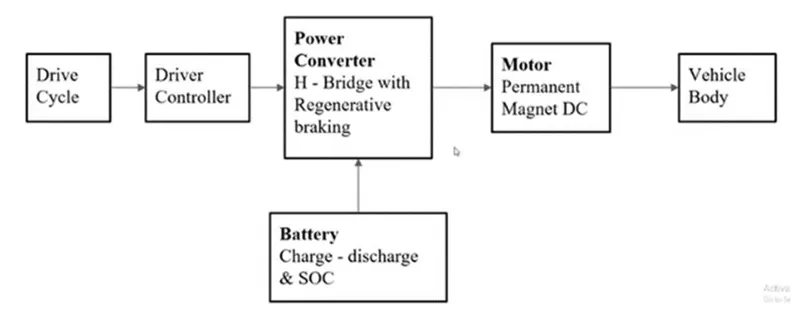
- Drive Cycle: It is used to input the data into the driver controller.
- Driver Controller: It controls the Acceleration and Deceleration of the vehicle.
- Power Converter: It consists of H-Bridge with Regenerative Braking, H-Bridge is used to drive the DC Motor.
- Battery: It indicates the charge and discharge condition and the % SOC (State of Charge) variations with respect to the drive cycle.
- Motor: It indicates the Motor Positioning and type of Motor we are using.
- Vehicle Body: It indicates the Mechanical Structure of an EV.
- Battery:
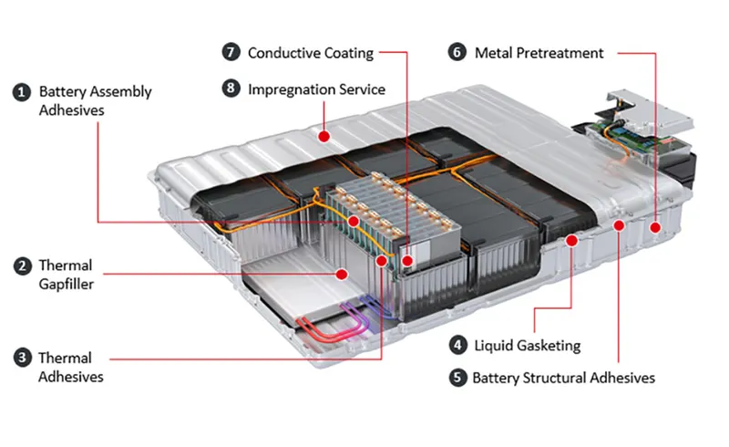
- Most electric vehicles use lithium-ion batteries (Li-Ions or LIBs). Lithium-ion batteries have a higher energy density, longer life span and higher power density than most other practical batteries. Complicating factors include safety, durability, thermal breakdown and cost. Li-ion batteries should be used within the safe temperature and voltage ranges in order to operate safely and efficiently.
- Increasing the battery's lifespan decreases effective costs. One technique is to operate a subset of the battery cells at a time and switching these subsets.
- In the past, nickel-metal hydride battery batteries were used in some electric cars, such as those made by General Motors. These battery types are considered outdated due to their tendencies to self-discharge in the heat. Furthermore, a patent for this type of battery was held by Chevron, which created a problem for their widespread development. These factors, coupled with their high cost, have led to lithium-ion batteries leading as the predominant battery for EVs.
- The prices of lithium-ion batteries are constantly decreasing, contributing to a reduction in the price of electric vehicles.
- Li-ion Battery:
- Most EVs use Lithium-ion Batteries(Li-ions).
- Li-ion Batteries have Hgher Energy Density, Longer Life Span and Higher Power Density than other types of Batteries.
- While Using Li-ion Batteries care must be taken for the following factors: Safety, Durability, Thermal Breakdown.
- This type of batteries should be used within Safe Temperature and Voltage Ranges in order to operate safely and efficiently.
- Battery Management System:
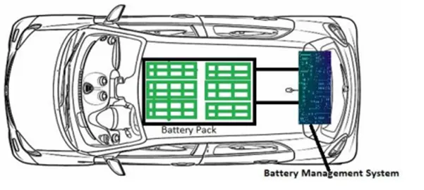
- Battery Management System (BMS) as the name says it manages the batteries many cells so that they can operate as a Battery Pack.
- In EV, Battery consists of more than tens to thousands of Li-ion Cells, and each cell is needed to be operated in similar conditions in order to optimize the Battery's durability and performance.
- BMS functions is to monitor the Cell's Charge and Discharge status, but if it detects some faults within a particular cell, it will automatically adjust the power status of the call i.e. ON/OFF through switching mechanism.
- Electrical Motor:
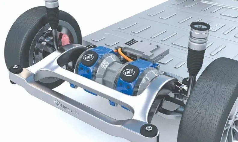
- The power of a vehicle's electric motor, as in other machines, is measured in kilowatts (kW). Electric motors can deliver their maximum torque over a wide RPM range.
- This means that the performance of a vehicle with a 100 kW electric motor exceeds that of a vehicle with a 100 kW internal combustion engine, which can only deliver its maximum torque within a limited range of engine speed.
- The efficiency of charging varies considerably depending on the type of charger, and energy is lost during the process of converting the electrical energy to mechanical energy.
- Usually, direct current (DC) electricity is fed into a DC/AC inverter where it is converted to alternating current (AC) electricity and this AC electricity is connected to a 3-phase AC motor.
- For electric trains, forklift trucks, and some electric cars, DC motors are often used. In some cases, universal motors are used, and then AC or DC may be employed. In recent production vehicles, various motor types have been implemented; for instance, induction motors within Tesla Motor vehicles and permanent magnet machines in the Nissan Leaf and Chevrolet Bolt.
- Motor Controller:
- The motor controller of an electric car administers its complete operation and the distribution of its power at any given moment. It acts as a floodgate between the motor and batteries.
- It helps monitor and regulates all key performance indications such as the vehicle's operator, motor, battery, and accelerator pedal. It has a microprocessor that can limit or redirect current.
- It is used to either improve the mechanical performance of the car or suit the operator's driving style. There are also more refined controllers which are capable of greater accuracy and thus, higher efficiency.
- Electric Power Control Unit:
There are many types of control units used in an EV they are:
i. Inverter
ii. Low Voltage DC-DC Converter
iii. Vehicle Control Unit
i. Inverter:
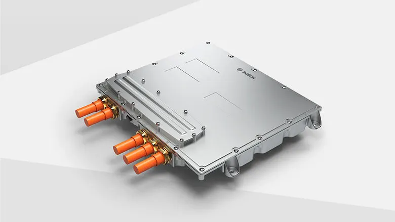
- The basic function of an Inverter is to convert DC signal to AC signal, here the BAttery's DC signal gets converted into AC signal, which is used by an Electric Motor to control the speed of motor.
- It is responsible for acceleration and deceleration, so it serves a crucial part in maximizing EV's durability.
ii. Low Voltage DC-DC Converter:
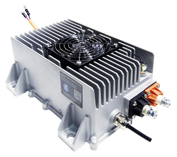
- DC-DC Voltage Converter, it converts the High Voltage signal from the High Voltage Battery into Low Voltage (Typically between 12-24V) and it is then given to the Electric Vehciles Auxiliary systems which works on low voltage.
- Auxiliary systems includes: Head lights, Tail lights, AC Compressor, Infotainment systems, etc.
iii. Vehicle Control Unit:
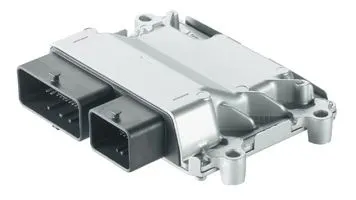
- It is the important component in the Electric Power Control Unit.
- The main function of this is that it oversees nearly all the vehicles power control mechanisms, which includes Motor Control, Regenerative Braking Control, A/C Load Managemnet and Power Supply for the Electronics Systems.
- Charger:
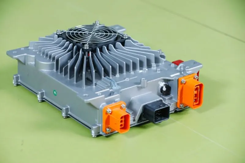
- Charger is also one of the main component in EV's, it's used to charge the battery of an EV.
- The input of the Chargers, is taken from outside sources like the Grids or Solar Power Plants.
- AC Power is converted into DC Power and then it is stored in the Battery.
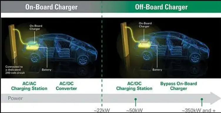
- Two types of chargers are available:
i. On-Board Charger: This charger is located and installed inside the vehicle.
ii. Off-Board Charger: This type of charger is not loacted or installed in the vehicle.
- Model Parameters:
- MATLAB Modelling:
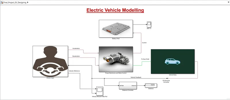
1.Vehicle Body subsystem:
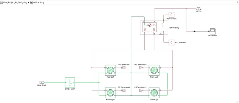
- Represents a two-axle vehicle body in motion.
- Accounts for body mass, aerodynamic drag. grade, externally defined mass and centre of gravity of the vehicle body.
- Input Ports:
W = Wind Velocity in m/s
beta = Grade angle in radians
- Output Ports:
V = Velocity in m/s
NR = Normal force on Rear Axle (N)
NF = Normal Force on Front Axle (N)
- Vehicle Body Parameters:
Vehicle body mass, Centre of gravity distance values and aerodynamic drag
variables are modified. Pitch dynamics are kept ON with other variable values as default values.
1.1. Tire:
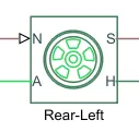
The vehicle is assumed to be front axle is driven (4 wheels- 2 on each axle).
The wheels are modelled using simple Tire (Magic formula) Simulink blocks.
The block can model tire dynamics under constant or variable contact surface
conditions.
- Input Port:
N = Normal force acting on the tire, positive when force is acting downwards/towards the contact surface.
- Output Port:
S = Slip value is relative to tire and surface of contact.
- Conserving Ports:
H=represents wheel hub which transmits thrust generated by the wheel to the body of the vehicle.
A=represents the axle on which the tires are mounted.
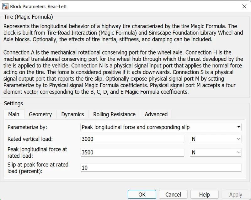
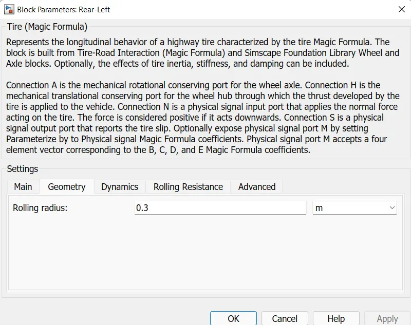
- The tires are parameterized by Peak longitudinal force and corresponding slip
- The other block parameters such as rated vertical load, peak longitudinal force at rated load and slip at peak force at rated load - are kept with their default values.
1.2. Gear:
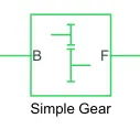
A simple gear block is used to connect the motor to the rear axle of the vehicle.
It represents the gearbox that connects the input shaft to the base gear and output from the follower gear.
- Conserving Ports:
B = port associated with an input shaft (motor shaft)
F = port associated with the output shaft (axle/ differential)
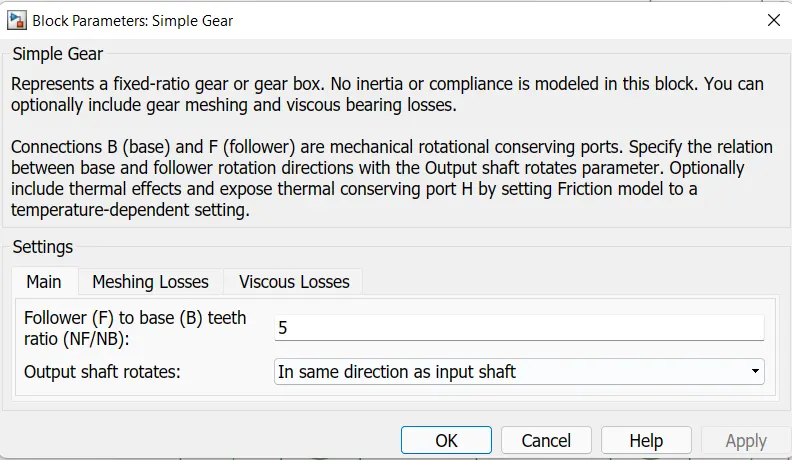
- Simple Gear Parameters:
Gear ratio and output direction are modified. Meshing loss is kept constant and gear is having a constant efficiency throughout the simulation. Viscous losses and faults are kept at default conditions.
1.3. Vehicle Body:
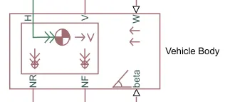
- This block basically represents a two-axle vehicle body in longitudinal motion. The block accounts for - body mass, aerodynamic drag, road incline, weight distribution between axles due to acceleration road profile.
- Here, connection H is the mechanical translational conserving port hub.
- NF & NR correspond to the output ports for normal reaction forces on the front axle and rear axle wheels respectively.
- Connection V represents the actual output translational velocity of the vehicle.
- beta is the road inclination angle & W corresponds to the headwind speed (headwind direction opposite to that of the vehicle).
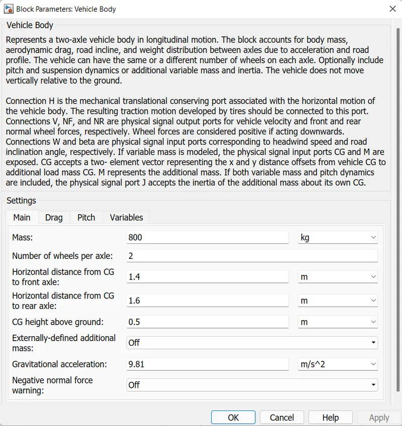
- The gross weight is given to be 1000 kg
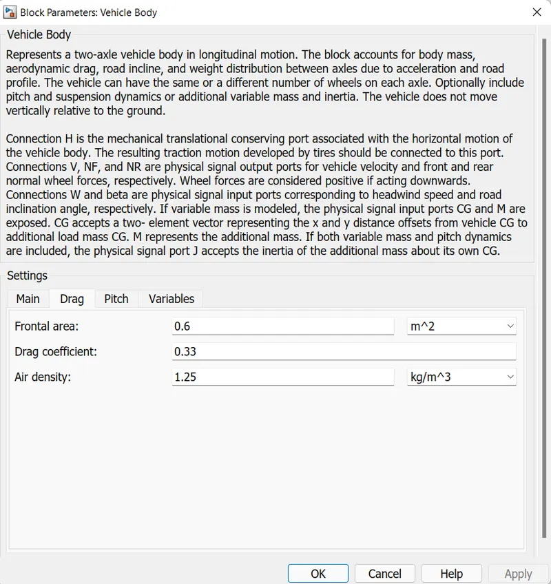
- The geometric parameters of the vehicle are given as:
2. Power Electronics and Motor Control Subsystem:
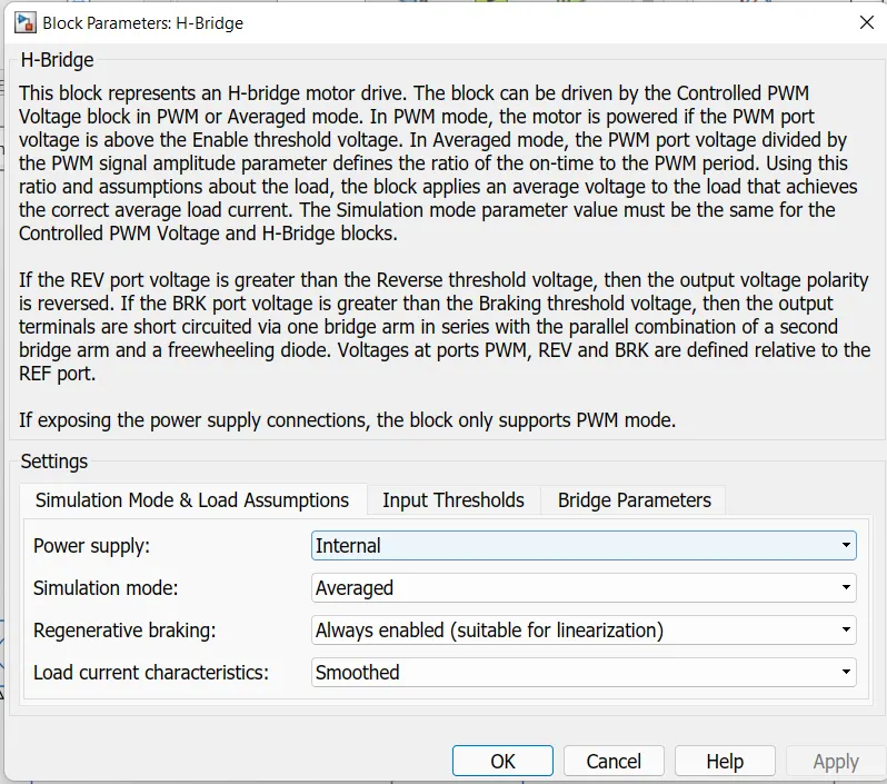
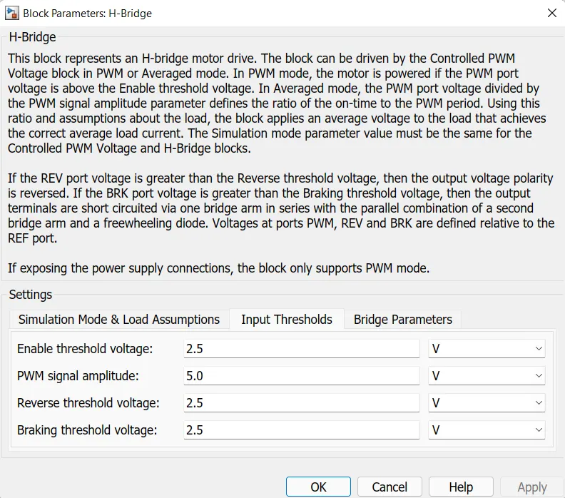
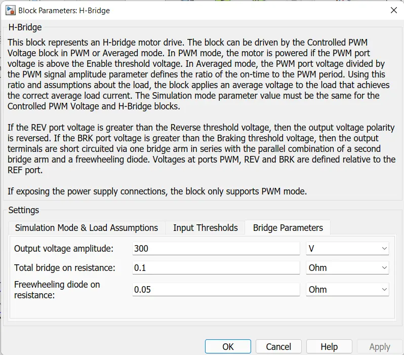
2.1. H-Bridge:
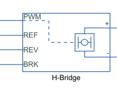
The H-Bridge helps in controlling the power that is input according to the requirement. The output provided is converted voltage as per the controlled parameters.
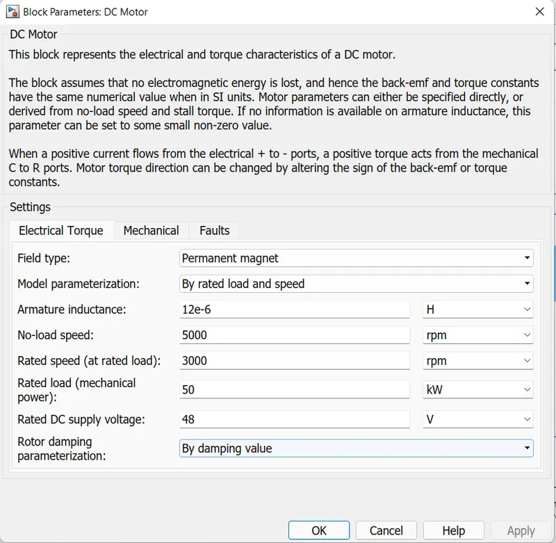
2.2. DC Motor:
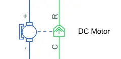
This is the DC Motor which would give rotational power to the wheels and become the sole power generation source.
The DC Motors terminals are connected as mentioned below:
- + =Electrical signal to the motor Positive Terminal
- - =Electrical signal to the motor Negative Terminal
- R=Casing of the Motor connected with the Mechanical Rotational Reference Block
- C=Rotor Case connected to the Mechanical Rotational reference
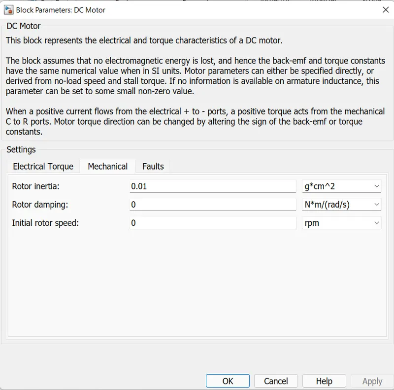
The parameter considered is, The Armature inductance is as default, varied the changes in the No-Load Speed 5000 rpm, the rated speed 3000 rpm, the Rated Load at 50kW, and the Rated DC Supply Voltage 48 V. All other parameters are as default.
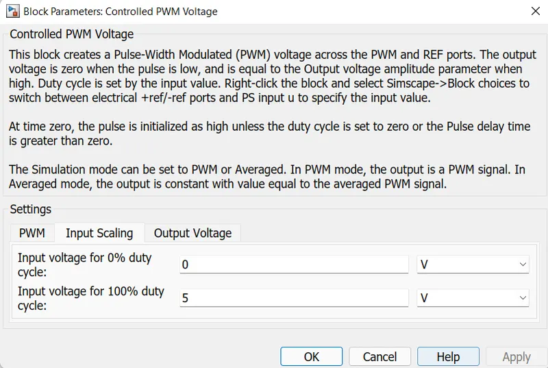
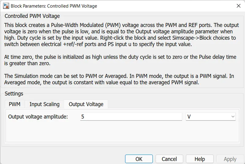
2.3. Controlled PWM Voltage:
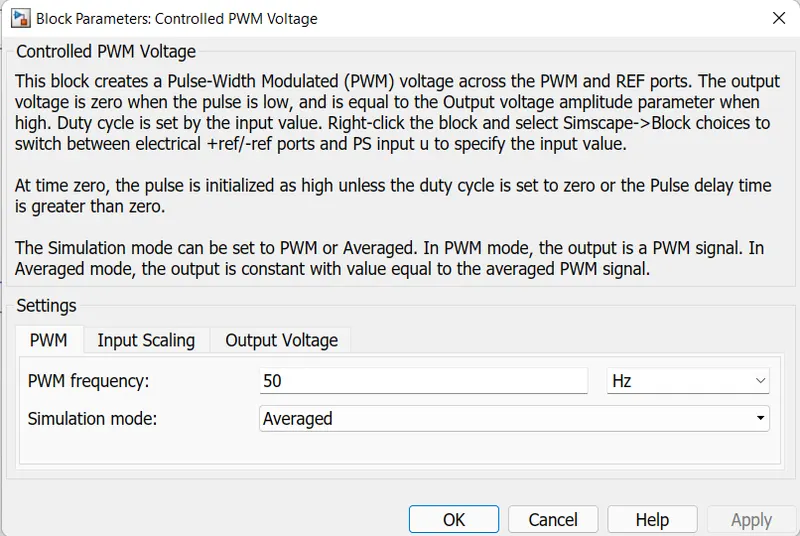
The Controlled PWM Voltage Block helps in keeping the Modulated Pulses as per the required pulses. So that the operations happen smooth and higher variations are not observed.
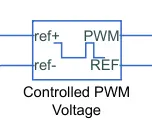
The Ports are connected as follows:
- PWM=PWM connected directly to the H-Block
- REF=REF connected directly to the H-Block
- ref+ = Reference Positive connected with Driver Model ith the Acceleration Commands from the
- ref- =Reference Negative connected with the Deceleration Commands from the Driver Model
2.4. Controlled Voltage Source:
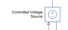
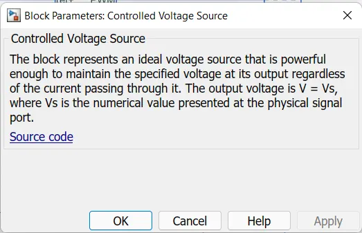
- The Controlled Voltage Source block converts a Simulink input signal into an equivalent voltage source.
- The generated voltage is driven by the input signal of the block.
- Controlled Voltage Source block with a specific AC or DC voltage.
- In steady state, the Simulink input must be connected to a signal that begins the simulation as a sinusoidal or DC waveform that corresponds to the initial values.
- In our model,we have used 2 Controlled Voltage Source bocks one is connected to the positive terminal is connceted to the positive reference terminal of the Controlled PWM Voltage block and the negative terminal is connected to the Common Ground.
- Physical port is connected to the Connecvtion Port 2 which indicates the Acceleration.
- The other block, the positive terminal is connected to the Break Port of H-Bridge block and the negative terminal is connected to the common ground.
- Physical port is connected to the Connection Port 3 which indicates the Deceleration.
2.5. Current Sensor:
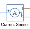
- It indicates an idealcurrent sensor, it means that, a device that converts current measuredin any electrical branch into a physical signal proportional to the current.
- The positive and the negative ports through this sensor is inserted in between the H-Bridge and the DC Motor.
- Connection I is the physical signal output port for the measurement of result current.
2.6. Voltage Sensor:
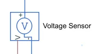
- The Voltage Sensor block indicates an ideal voltage sensor,i.e., a device that converts voltage measured across the motor into a physical signal proportional to the voltage.
- The positive and the negative ports are technical conserving ports through which the sensor is connected to the circuit.
- V port is the physical signal port that measures the result of voltage across the motor.
2.7. Solver Configuration:
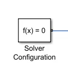
- Each physical network represented by a connected Simscape block diagram requires solver settings information for simulation.
- The Solver Configuration block specifies the solver parameters that your model needs before you can begin simulation.
- Each topologically distinct Simscape block diagram requires exactly one Solver Configuration block to be connected to it.
- The block has one conserving port. We can add this block anywhere on a physical network circuit by creating a branching point and connecting it to the only port of the Solver Configuration block.
2.8. PS-Simulink Converter:
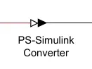
- The PS-Simulink Converter block converts a physical signal into a Simulink output signal.
- This block to connect outputs of a Physical Network diagram to Simulink scopes or other Simulink blocks.
- To convey signal conversion while taking up minimal canvas space, the block icon changes dynamically based on whether it is connected to other blocks.
2.9. Electrical Reference:
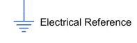
- The Electrical Reference block represents an electrical ground.
- Electrical conserving ports of all the blocks that are directly connected to ground must be connected to an Electrical Reference block.
- A model with electrical elements must contain at least one Electrical Reference block
2.10. Mechanical Rotational Reference:

- The Mechanical Rotational Reference block represents a reference point, or frame, for all mechanical rotational ports.
- All rotational ports that are rigidly clamped to the frame (ground) must be connected to a Mechanical Rotational Reference block.
2.11. Scope:
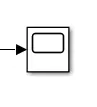
- Through this block we can observe the resultant plots.
- We can add the additional ports to view the another plots in 1 Scope Block.
- We can select the legend option in the plot to view the name of the plot and also set the layout to view the different plots.
2.12. Connection Ports:
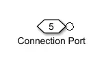
- The Connection Port block transfers a physical connection or signal across subsystem boundaries.
- A subsystem needs a Connection Port block for each physical connection line that crosses its boundary.
- We can manually place a Connection Port block inside a subsystem, or Simulink can automatically insert a Connection Port block when you create a subsystem within an existing network.
3. Battery Pack Subsystem:
3.1: Battery:
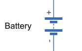
- This block represents a Simple Battery Model, which is shown below.
- When the positive and negative terminals of Battery is connected to the Controlled Current Source and the Electrical Reference (Ground).
- Battery is the prime mover in an Electric Vehicle as it provides the power for the propulsion of the vehicle.
- We can check the Battery Charging and Discharging conditions according to the monitoring and braking actions.
- The following figure shows the block parameters of the Battery:
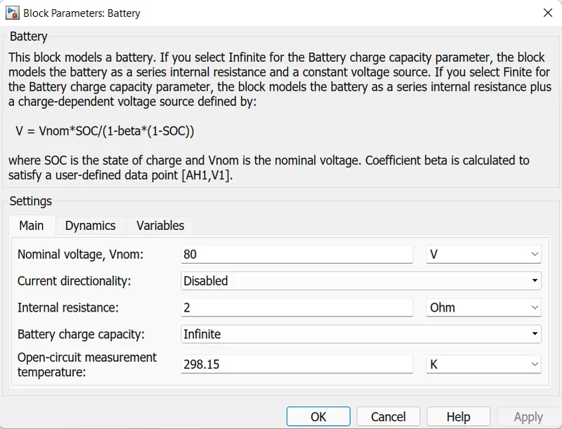
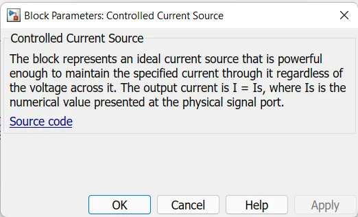
3.2: Controlled Current Source:
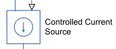
- The Controlled Current Souce block represents an Ideal Current Source that is powerful enough to maintain the specified current through it regardless of the voltage accross the source.
- This block is connected across the Battery.
- It contains 1 physical signal input port and 2 electrical ports associated with its Electrical Terminals.
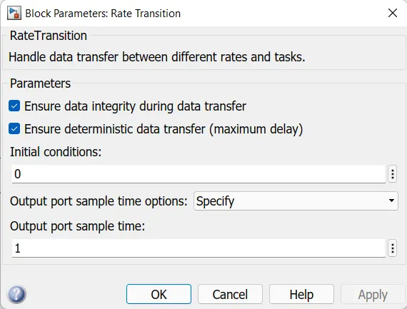
3.3. Rate Transition:
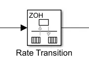
- This block transfers the data from the output of a block operating at one rate to the input of a block operating at a different rate.
- By using the parameters we can trade data intergrity and deterministic transfer for faster response or lower memory requirements.
- In our model, from the Battery Current to calculate the SOC of the battery.
- It has 1 input and 1 output port.
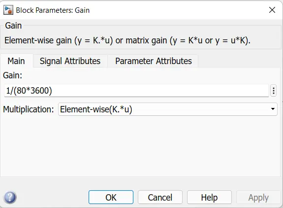
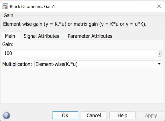
3.4. Gain:
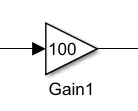
- This block multiplies the input by a cnstant value.
- It has 1 input and 1 output port.
- In our model, we are using 2 gain blocks as mentioned above.
3.5. Discrete Time Integrator:
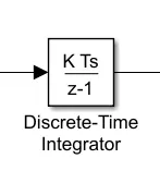
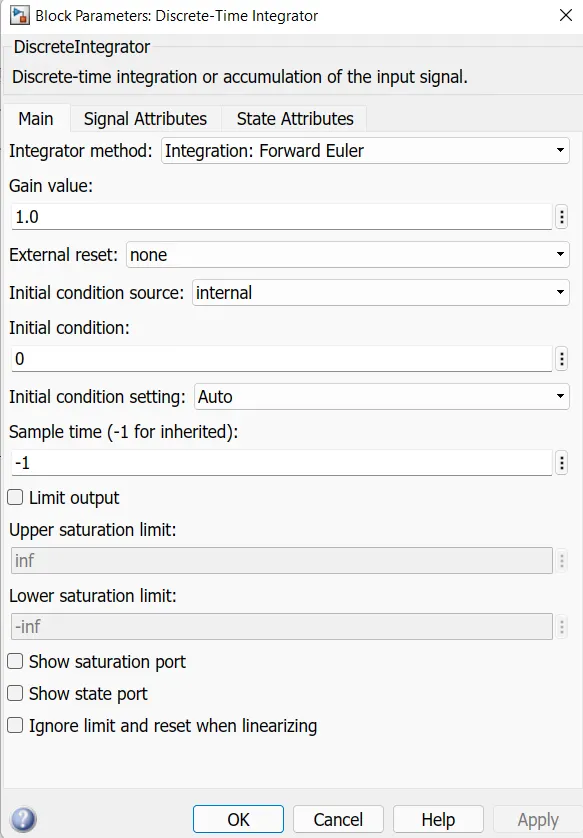
- The Discrete Time Integrator Block is used instaec of Intergrator block to create a purely discrete model.
- In this block, we can define Initial Conditions, Input Gain Value, Upper and Lower Limits on the Intergral.
- This block has 1 input port and 1 output port.
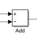
3.6. Add:
- The Add block is used to add the input values and give the result through its output.
- Here we are taking 2 inputs from the Discrete Time Intergartor and other from Constant Value from Constant Block.
4. Drivers Input Subsystem:
4.1. Drive Cycle Source:
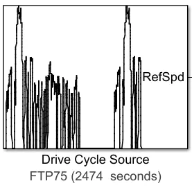
The Drive Cycle Source block generates a standard or user-specified longitudinal drive cycle. The block output is the specified vehicle longitudinal speed, which you can use to:
-
Predict the engine torque and fuel consumption that a vehicle requires to achieve desired speed and acceleration for a given gear shift reference.
-
Produce realistic velocity and shift references for closed loop acceleration and braking commands for vehicle control and plant models.
-
Study, tune, and optimize vehicle control, system performance, and system robustness over multiple drive cycles.
-
Identify the faults within tolerances specified by standardized tests, including:
i. EPA dynamometer driving schedules.
ii. Worldwide Harmonised Light Vehicle Test Procedure (WLTP) laboratory tests.
In our model we have used 2 Drive Cycles which are discussed below:
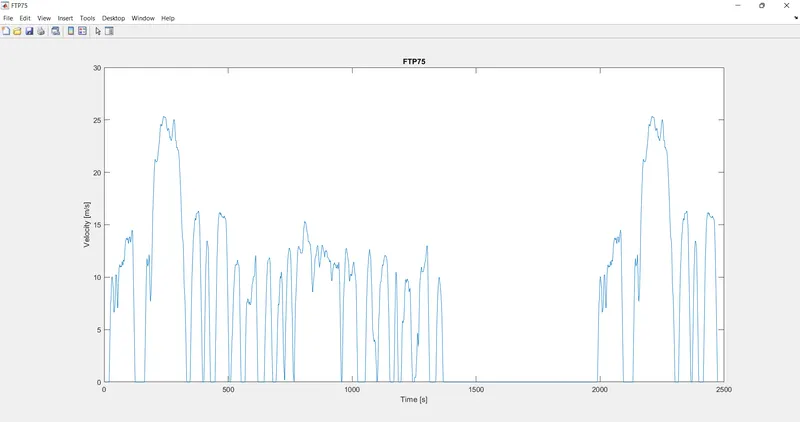
- FTP75 Drive Cycle:
-
FTP75 drive cycle from a .
matfile into a 1-D Lookup Table block. The FTP75 represents a city drive cycle that you can use to determine tailpipe emissions and fuel economy of passenger cars. -
Wide Open Throttle (WOT) parameters to specify a drive cycle for performance testing.
-
Workspace Variable it Specify time, speed, and, optionally, gear data as a structure, 2-D array, or time series object.
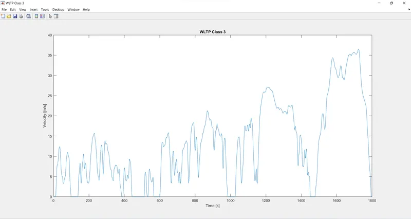
- WLTP Class - 3 Drive Cycle:
-
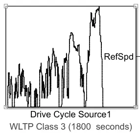
The average energy consumption of the vehicle will be calculated on a homologation cycle. For our example we are going to use the WLTC drive cycle.
-
The test procedure WLTP (Worldwide harmonized Light vehicles Test Procedure) contains several driving cycles:
i. Class 1 – low power vehicles with PWr <= 22
ii. Class 2 – vehicles with 22 < PWr <= 34
iii. Class 3 – high-power vehicles with PWr > 34
Where,
PWr [kW/Tonne] is the power-to-weight ratio.
4.2. Longitudinal Driver:
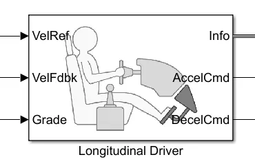
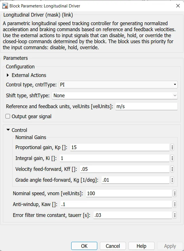
- Longitudinal Driver is an inbuilt block provided by the powertrain blocks.
- It is a parametric longitudinal speed tracking controller for generating normalized Acceleration and Braking commands based on reference and feedback velocities,
- The VelFdbk port corresponds to the feedback velocity. The actual velocity output given by the vehicle body is connected here. By comparing the actual (feedback) velocity with the reference velocity, the driver block generates acceleration and braking signals in order to minimise the error between the two concerned velocities.
- Grade corresponds to the grade angle. For this simulation, no inclination is considered and hence, a constant block with value 0 is connected.
- Info gives the output for the bus signal for different block calculations like the difference in reference vehicle speed and vehicle speed, etc.
- AccelCmd & DecelCmd correspond to the acceleration and deceleration commands generated respectively and are connected to the corresponding ports of the Controlled PWM Voltage block Here, the selected control type is Pl. Accordingly, the block implements proportional-integral (PI) control with tracking windup and feed-forward gains.
4.3. Multiport Switch:
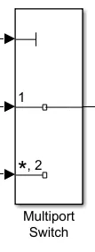
- The Multiport Switch block determines which of several inputs to the block passes to the output. The block bases this decision on the value of the first input.
- The first input is the control input and the remaining inputs are the data inputs.
- The value of the control input determines which data input passes to the output.
4.4. Terminator:
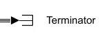
- Terminator block is used to cap blocks whose output ports do not connect to other blocks.
- If you run a simulation with blocks having unconnected output ports, Simulink issues warning messages.
- Using Terminator blocks to cap those blocks helps prevent warning messages.
4.5. Powergui:
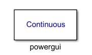
The powergui block allows you to choose one of these methods to solve your circuit:
-
Continuous, which uses a variable-step solver from Simulink.
-
Discretization of the electrical system for a solution at fixed time steps.
-
Continuous or discrete phasor solution.
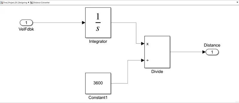
5. Distance Converter Subsystem:
- It will display velocity of the vehicle with the help of Display Block.
- To measure the distance, an integrator block is used because the interaction of velocity will give us distance and 3600 constant blocks are used because 1hr=3600sec.
- Simulation:
- We have 2 Drive Cycles, for FTP 75 Drive Cycle, we are running our simulation for the time of 2474 secs.
- For WLTP Class 3 Drive Cycle, we are running our simulation for the time of 1800 secs.
- By clicking on the run button on the top we can run the simulation after setting the run time as mentioned above.
- Results:
i. FTP75 Drive Cycle:
1. Drive Cycle Plot:
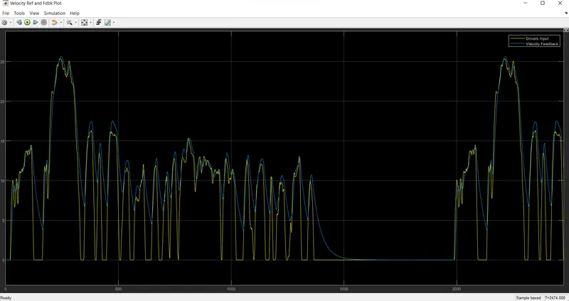
The Yellow line is a graph of the Drive Cycle source and the Blue line shows the corresponding Velocity graph.
2. SOC Plot:
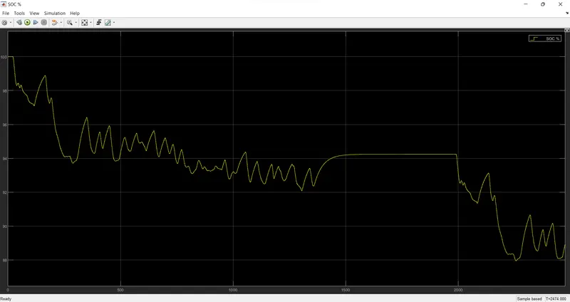
- The plot has been observed from the scope block wj=hich is connected at the battery subsystem.
- The above plot represents the variations in State of Charge (SOC), that is charging and discharging conditions of the battery.
3. Current Sensor Plot:
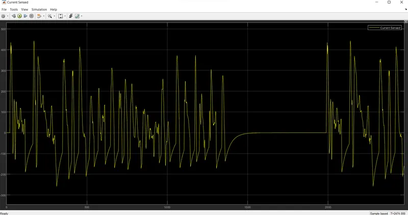
The plot shows the current variations of the motor according to the drive cycle.
4. Voltage Sensor Plot:
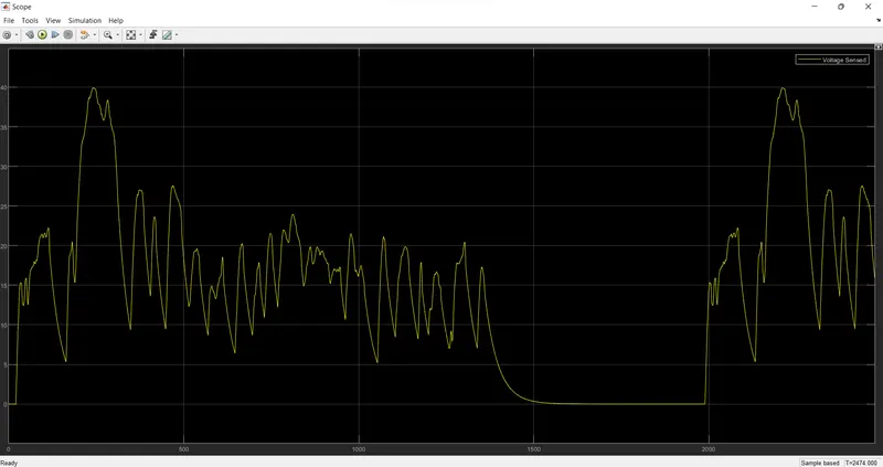
The plot shows the voltage variations of the motor according to the vehicles acceleration and deceleration conditions.
5. Velocity Plot:
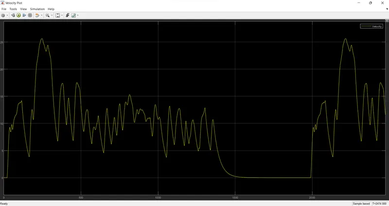
- If we observe the above two plots they are almost similar.
- This block is connected to the vehicle body, it gives the actual velocity changes happened in the vehicle.
ii. WLTP Class 3 Drive Cycle:
1. Drive Cycle Plot:
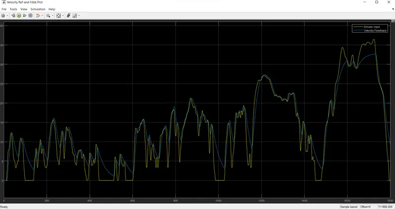
The Yellow line is a graph of the Drive Cycle source and the Blue line shows the corresponding Velocity graph.
2. SOC Plot:
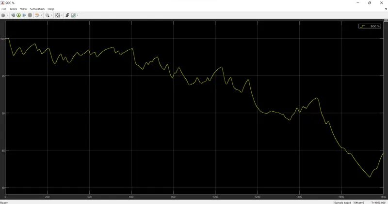
- The plot has been observed from the scope block wj=hich is connected at the battery subsystem.
- The above plot represents the variations in State of Charge (SOC), that is charging and discharging conditions of the battery.
3. Current Sensor Plot:
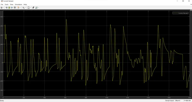
The plot shows the current variations of the motor according to the drive cycle.
4. Voltage Sensor Plot:
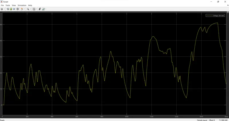
The plot shows the voltage variations of the motor according to the vehicles acceleration and deceleration conditions.
5. Velocity Plot:
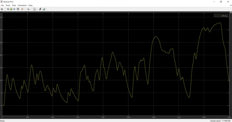
- If we observe the above two plots they are almost similar.
- This block is connected to the vehicle body, it gives the actual velocity changes happened in the vehicle.
- Conclusion:
- The MATLAB Model of an Electric Vehicle is created by using DC Motor and Battery as well as it is simulated and results have been plotted above.
- As we can see from the graphs is that the model is following the almost similarly to the Drive Cycles i.e. inputs FTP75 and WLTP Class 3 and the result is shown above.