Final Project: Design of an Electric Vehicle
AIM:
Create a MATLAB model of electric car which uses a battery and a DC motor. Choose suitable blocks from Powertrain block set. Prepare a report about your model including following:
Objectives:
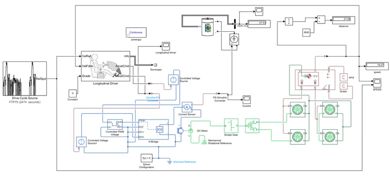
1. System level configurations
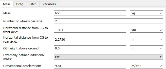
2. Model parameters
3. Results
4. Conclusion
METHODOLOGY:
Introduction:
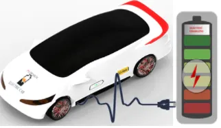
Battery Electric Vehicles (BEVs) are fairly simple and
easy to operate when compared to classic internal combustion engine (ICE) vehicles. BEVs are also called pure electric vehicles.
The powertrain architecture encompasses
- high voltage battery
- an electric motor
- power electronics controller
- single speed gearbox.
The propulsion is based on the electric energy stored in the high voltage battery.
The usage of BEV's are increasing in market duet to hike in fuel prices and move towards cleaner renewable fuel with high
efficiency, reliability and relatively low cast of the electric motor. The con of BEV's is the low energy density of the
high voltage battery.
Simulink Design Layout:
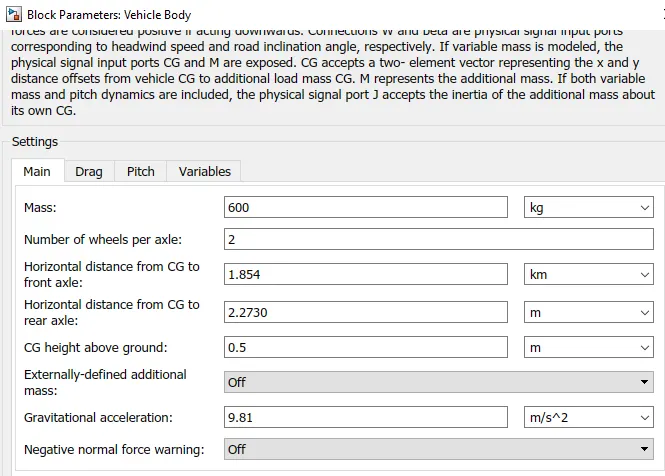
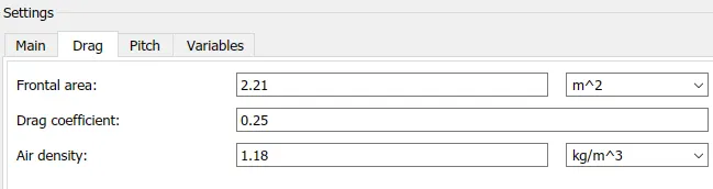
Vehicle Technical Spec:
Drive Cycle:
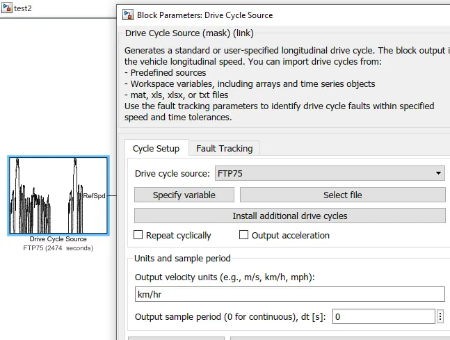
FTP75 Driver cycle is selected here and the duration of the cycle is 2474 sec.

DRIVER MODEL
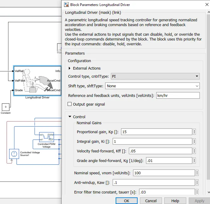
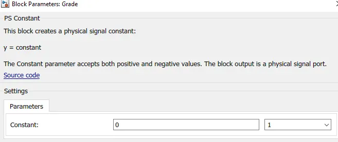
Inference: Vehicle reference of the driver model is connected to the drive cycle FTP75. The velocity feedback is connected to vehicle body to meet required speed based on input as a closed loop feedback. The grade of road is zero. Accleration command is connected to controlled PWM source trhough controlled PWM voltage that vary durty cycle w.r.t input. Deceleration command is connected to brake H-bridge to decelrate and maintain speed w.r.t to drive cycle.
PI integral is used to match the throttle pedal from driver w.r.t the input drive cycle given and will acclerate or deccelerate accordingly.
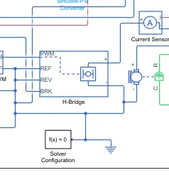
H-Bridge
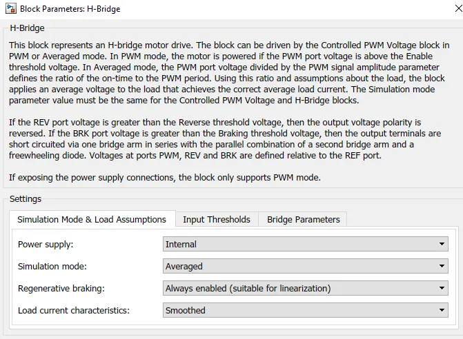
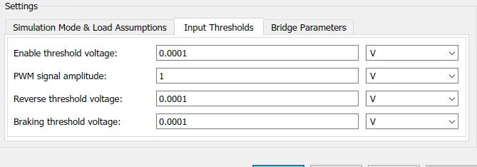
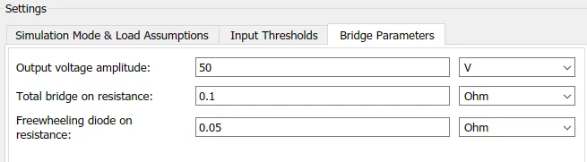
The H-Bridge controls the power that is input according to the requirement by converting the output converted voltage as per the controlled parameters.
The Ports for Input and Output:
- PWM - Pulse Width Modulation
- REF - Controlling with Reference
- REV - Controlling with Reverse
- BRK - Controlling the Brake and Regenerative
- += Controlled Output to the positive Terminal of the Motor
- - = Cotrolled Output to the Negative Terminal of the Motor
DC Motor
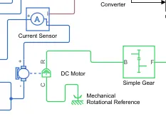
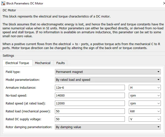
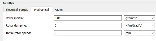
Inference: DC Motor C is connected to casing of the motor connected with mechanical rotational reference block. R is rotor shaft of dc motor which is connected to simple gear train to vary torque and speed.
Battery Source
Li Ion Battery Source is connected as source to the model to generate power to operating sources and load demand of driver.
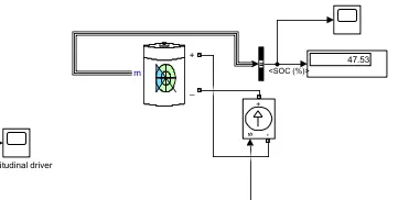
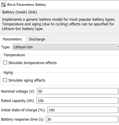
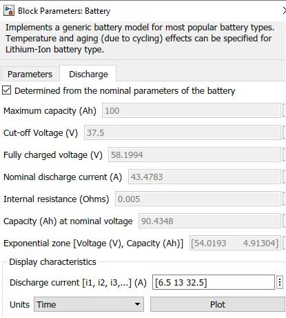
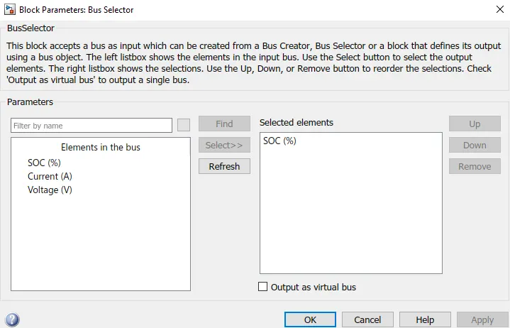
Inference: The SOC is estimated by using a display SOC block connected with Li ion battery battery through a bus selector
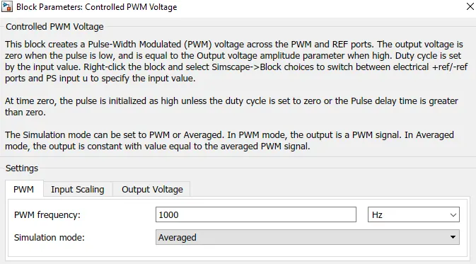
It assists in maintaining the modulated pulses as per the required pulses for smooth operations and higher variations. For less simulation time Average simulation mode is selected.



Vehicle
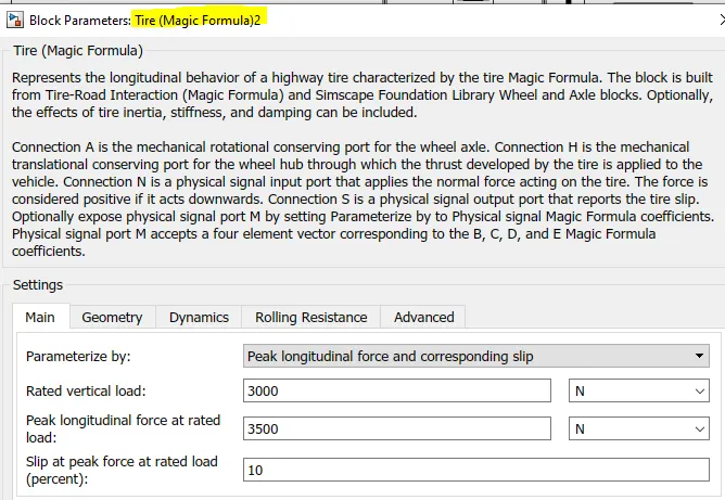
The components of vehicle
Gear: maintains required torque speed
Tyre -4Tyre
Vehicle block
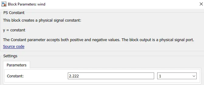
Angle: Slope of road
Wind speed
Velocity of car
NF and NR - Front and rear wheel connection





OUTPUT:
Scope 1
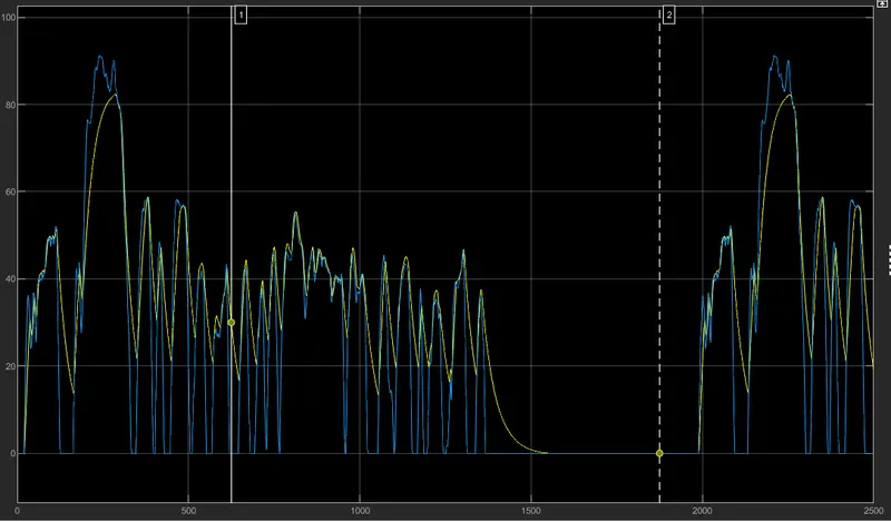
Velocity Feedback and drive cycle source
Inference:
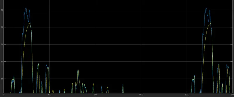
It is envisaged from the plot that the actual speed denoted in yellow lags behind and tries to follow the reference speed in blue. The vehicle nearly matches the max speed of drive cycle for given input and for more accuracy we can increase the rating of motor.
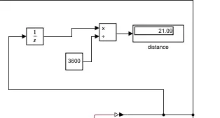
Distance travelled in one Driver cycle of duration 2474 seconds: 21 km
Display:
Battery SOC
Scope and Display:
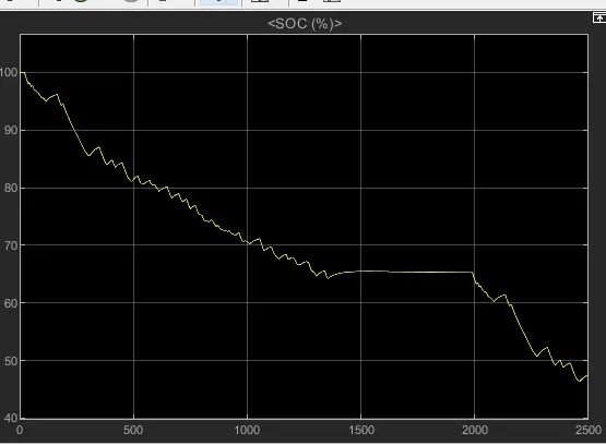
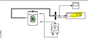
Inference: It is envisaged from the graph that the battery starts with 100% level initially and discharges with the operation of the vehicle for 2474 sec w.r.t FTP75 driver cylce and ends at 47.53 % lelvel. The spikes in battery SOC graph shows regeneration during the deceleration of the vehicle as battery starts recharging and motor acts as generator.
CONCLUSION:
The electric car was simulated using Li ion Battery source and DC Motor in Matlabsimulink and following observations were made:
- The vehicle has achieved the max speed of 82 km/hr but the FTP75 max speed is 91km/hr. Due to motor rating limitations a lag is observed.
- SOC after FTP75 cycle is 42 %
- Distance travelled is 21 km.