Final Project: Design of an Electric Vehicle
AIM- Create a MATLAB model of electric car which uses lithium ion battery and induction motor
Components-
The main components of EV are-
1.Batterries.
2.Power converters.
3.Motor/Generator controller.
4.Motor/Generator.
5.Transmission system.
6.Tyres/wheels.
Vehicle body -
We need to choose the vehicle body block to model the characteristics of body in matlab.
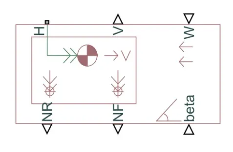
The six ports are used to model various characteristics of the vehicle body.
- H- This stands for Hub and is used to connect the hubs of the wheels to the main body of the vehicle.
- V- This is a physical signal output port which stands for Velocity and is used to output the speed / velocily at which the vehicle is moving at
- W- This is a physical signal input port and allows us to model a'headwind acting on the vehicle by giving a speed far it
- NR- This is a physical signal output port lo model the rear wheel normal forces.
- NF- This is a physical signal output to model the front wheel normal forces. .
- beta- This is a physical signal input port and allows us to model the vehicle on an inclination angle to create the effect of a hill climbing force.
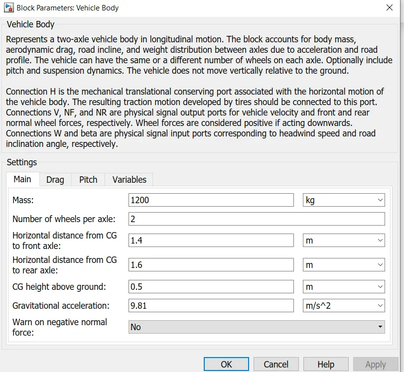
We need to double click on the block to model its parameters.
Firstly lets take main parameters i nwhich we can add the mass ,no of wheels and other parameters.Let us leave them as the default values given
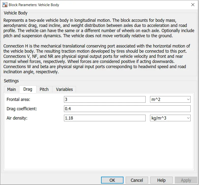
Now on clicking on the drag parameters we can change the parameters like drag coefficient,frontal area etc.
Changing the parameters there will be change in drag force whic is Fd = 0.5 * rho * A * V^2
Let us leave them to the default values.
Tires-
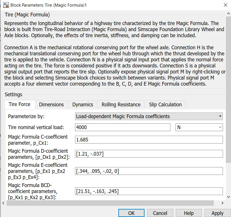
The tires used in this EV model are the'magic formula tires. There are several tire blocks that can be used for modelling a vehicle but I have used the magic farmula ones because it allows us to model the longitudinal behavior of vehicle tires on highways. They also allow us to model extra effects such as tire inertia, stiffness which allow for greater accuracy of real world conditions. The magic formula tire block is shown below.
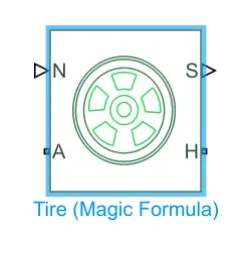
N - This port stands for Nomal and is the physical signal input port for the normal force acting on the tire and is considered positive in the dowrwards direction. .
S- This port stands far Slip and is the physical signal output port is that reports the slip acting on the tire.
A- This port stands for Axle and is the mechanical rolational conserving port far the wheel axle.
H- This port stands ror Hub and is the mechanical translational conserving port for the wheel hub through which the thrust developed by the tires is applied to the vehicle body
On double clicking we get settings let us change the tire force to load-dependent magic formula coefficient paramets and leave the values as default.
Slip-
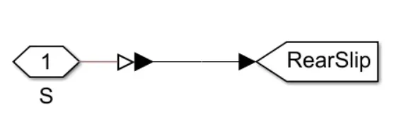
Sip The S port on the LR and LF tires are modeled with a certain degree of sip using a small subsystem. Ths system uses a PS-Simlink coverter will be used again later on for oher systerms in this EV model. The slip subsystem used for the magic formlae is shown in the image
Gear-
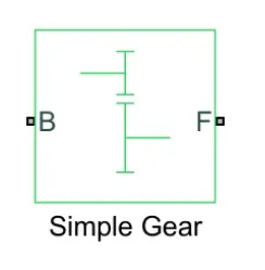
Next, we will model the transmission syatem of the EV ,i have used a Simple Gear block so as to simplify the transmission related parameters. The block models a gear system with a fixedd gear ratio with no inertia effects however we Can modify the effects of the meshing of gear teeth. The simple gear block shown below.
Side shaft-
An inertia block has been added to the workspace to provide an ideal mechanical rotaticnal inertia for the simple gear block. This block has only one mechanical rotational conserving port and the positive direction of the block is from the port to the reference point which would be the simple gear in this case. The inertia torque acts in the positive direction is the inertia is accelerated in the positive directicn The inertia block is shown below.

Velocity subsystem-
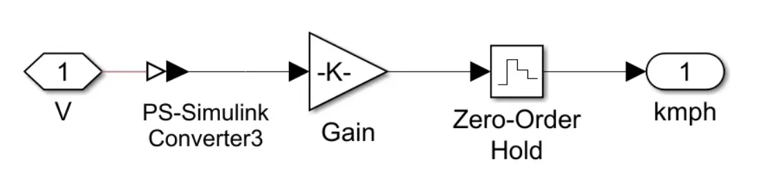
The velocity port which oulputs the velocity signal of the vehicle body block has been modified .By default the velocity signal that is output from the vehicle body block is measured in miles per hour To change these units I have implemented a small subsystem from the output of the velcity port.
This subsystem uses the following blocks.
PS-Simulink converter this block will comvert the physical signal of velocity to a logic signal. .
Gain- This block uses a multiplication factor of 1.6 10 comvert the miles per hour units to kilometres per hour.
Zero-Order Hold- This block is used implement a zero order hold sample period The inside of the subsystem is shown below.
Vehicle body subsystem-
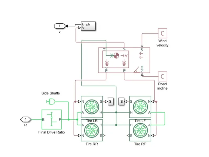
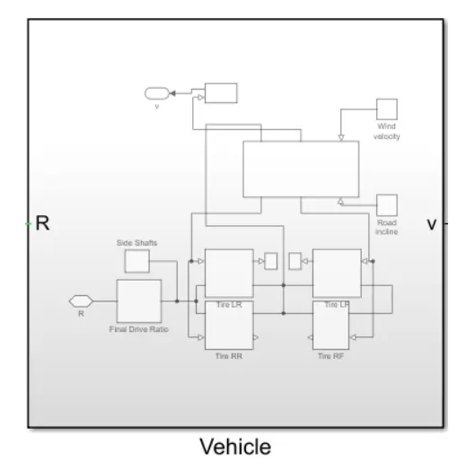
As seen in the diagram above, the various blocks are oonnected to model the vehicle body. 4 magic formula tire blocks are used as the vehide will have 4 tires, 2 on each axle The tires are LR, LE RR and RF (left rear left front, right rear and right front. The nomal pocts of each tire are connected to the appropriate NR and NF ports on the vehicle body block.The hubs of each tire are connected together and an extra connection is made from them to the vehicle body block.The S ports of the LR and LF 1 tires have been modelled with a slip using a smal subsystem The simple gear and inertia blocks are connected to the axle port of the tires The wind velocity and road incline aro provded with constant physical signals of 5mVs and 0 degrees respectiely. The velocity port has been cornected to the velooity subaystem and the commecticn from the subayatem is open to the V port The base port of the simple gear has been left open to the R port to take in a rotational signal If al these connections are made, all of these components can be selected and made in to a subsystem shown below.
The subsystem is created-
Motor-
Motor For the EV model, I have selected to use a DC motor block as the motor. This is because DC motors are easier to model and have fewer parameters to modify for a particular appication. For this model a DC motor will do just fine. The DC motor block is shown below.
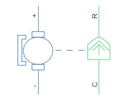
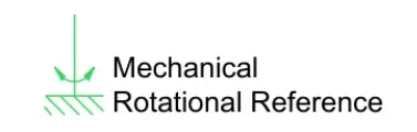
For this model a DC motor will do just fine. The DC motor block is shown below As we can see there are 2 sides to the block the mechanical side on the right and the electrical side on the left ,The mechanical side has 2ports C and R. The C refers to the casing and the R for the rotation of the rotor which produces a torque The electrical side has a positive and a negative terminal for the voltages to be applied. If a positve voltage is applied to the DC motor block from the positive to the negative teminal, a positive torque wil act from the C port to the R port. The direction of the forque produced by the DC motor can be changed by changing the sign of the back ernf cr the torque constant The C pont of the mechanical side reeds to be connected to amechanical rotational reference because il will be stationary The R port will be connected to the open connection of the simple gear from the vehicle body block. The positive terminal on the electrical side is connected to the positive terminal of a power converter which in my case wil be an H bridge .
The mechanical ratational refererce block is shown below
By double clicking we need to parameterize the properties of the motor and connect it as below
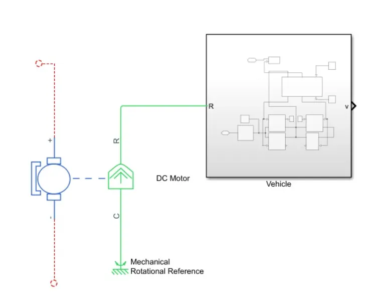
Power converter-
The power converter is needed to provide power of the correct form and magnitude from one component to another In the case of EVs a power converter is needed 10 provide a DC voltage frorm the battery of the EV to the DC motor so that it can operate properiy with the required parameters. As mentioned earlier, I have used an H Bridge motor drive as my power converte. Its block is shown below:
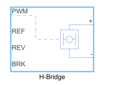
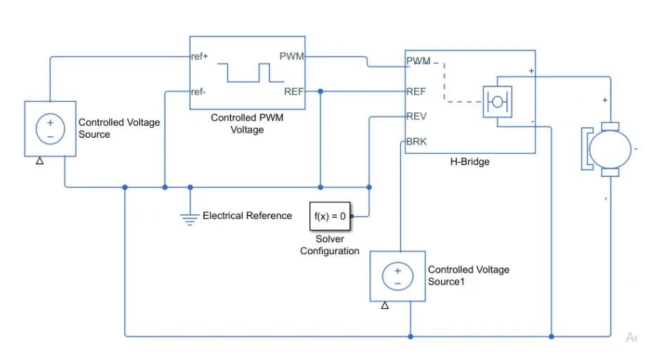
The H Bridge has 2 sides to it the left side is for the controlling of the voltage signals and the right side is for the terminals to provide the controlled voltage to the Dc motor The left side ports of the HBridge block are. o
PWM-This stands for Pulse Width Modulation which will provide the voltage puises to the H-Bridge either in the PWM or average mode
REF-This stands for Reference
REV-This stands for Reverse. .
BRK-This stands for Brake.
Controlled PWM voltage-
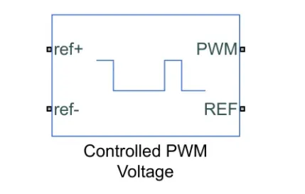
I have used a Controled PWM Votage block to provide a controlled pulse width moduated volhage to the HBridge biock The block will output the PWM voltage through its PWM and REF ports which will feed in to the same ports found on the HBndge biock If the pulse is low the output voltage is considered V whereas if the pulise is high, the output voltage will be equal to the output voltage ampitude which was set to 330V in the HBnidge block The pulses of voltage created by this block are dependent on the duty cycle which is the ratio of the time that the swilch is ON 10 the time taken for 1 cycle (wichis the lime for which the svitch is ON and OFF), The duty cycle is set by the input of the controlled PWM voltage block.
The block is shown as below.
Contolled voltage source-
The input ports of the controlled PWM voltage block are still unconnected and that is because they require a. voltage pulses to be fed in to the HBridge. For this, I have used the controlled voltage source block. This block is useful because i wil provide the necessary voltage that is pOwerful enough to maintain the voltage at the output regardiess of the current that passes through it This controlled voltage source biock is ahown below.
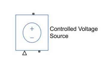
we need to add the electric refernce and solver configuration also , the connections comes as below
Longitudinal driver-
The Longitudinal Driver block implements a longitudinal speed-tracking controller. Based on reference and feedback velocities, the block generates normalized acceleration and braking commands that can vary from 0 through 1. You can use the block to model the dynamic response of a driver or to generate the commands necessary to track a longitudinal drive cycle.
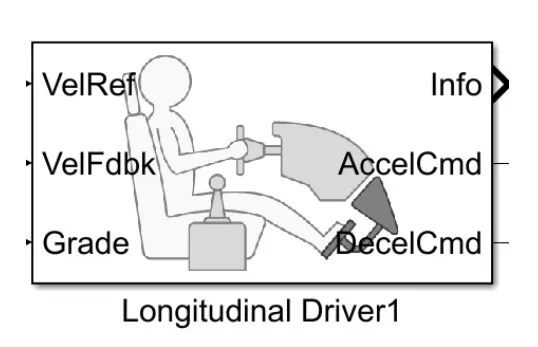
VelRef - This stands for the reference velocity and it is the velocity data provided from a drive cycle sounce.
VelFdbk-This stands for the foodback velocity and ic is the velocity data provided from the vehhicle body's velocity port which ouputs the velocity data.
Grade-This port provides a grade or inclnation angle for the surface on which the vehice is traveling in degrees.
Info- This port is for the bus signals which consist of block calculations e. g acceleraticn / deceleration command difference between reference and vehicle apeed.
AccelCmd-This port provides the acceleraticn command to a controlled voltage source. .
DecelCmd-This port provides the deceleraticn command to another controlled voitage source .
The working of the longitudnal drver block is smple. The referemce velocity data coming teom a drive cycle source is companed to the feedback velocity data coming from vehicle body block.If the reference velocity is greater than the feedback velocity an acceleration command will be given as an outpt to the cortrolled voltage source .If the reference velocity is lesser than feedback velocity, a deceleration command is given as the output to another controled voltage source instead. For the acceleration and deceleration oommands to be given as output signals, I have used a Simutnk-PS coverter block .This block is needed whenever we wish to connect a Simuink input sgnal to physical signal. In this case the input signal is velocity data and this is logic data which we want to convert to a physical signal i.e voltages to a contrlloed voltage source.
Drive cycle-
Drive cycle is a data set that contains veocity and time data for the purpose of modeling the motion of vehicle. The drive cycie wnli be a plot of the velocity against the time and it is made to resemble typical driving conditions that a driver may experience themselves in .For instance they can model highway drivng situations ,driving in urban aress or driving with full power etc. Drive cycles are used by automotive companies for various testing procedures such as mileage, pollution tests and acceleration and top speed tests. There are various different drive cycles that are industry standard eg Urban Dynamometer Driving Schedule(UDDS) FTP 75 .
In my EV model a drive cycle is used as the reference velocity data for the longitudnal driver block to send acceleration or deceleration commands according to the dive ycle There are 3 ways of implemerting a drive cycle.One method is to create of own drive cycle with spreadsheet of velocity data in one column and time data in another column,Another method is to use a signal bulder block and create signals that represent the velocities at which the vehicle should travel and the durations for which those velocities are to be maintaned ,The last method is to use the industry standard drive cycles which are in- bult in to the SIMLINK library.In my case, I have used an industry standard WOT drive cycle This drive cycle stands for Wide Open Throttle and a models the situation where the vehicle is made to accelerate at ful power and mantained at a particular speed and made to decelerate back to rest.
The drive cycie block is shown below.
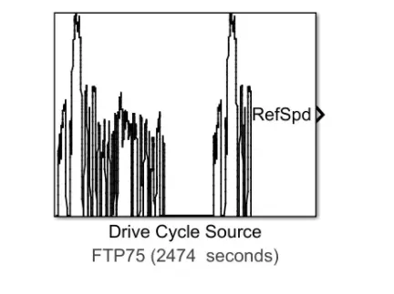
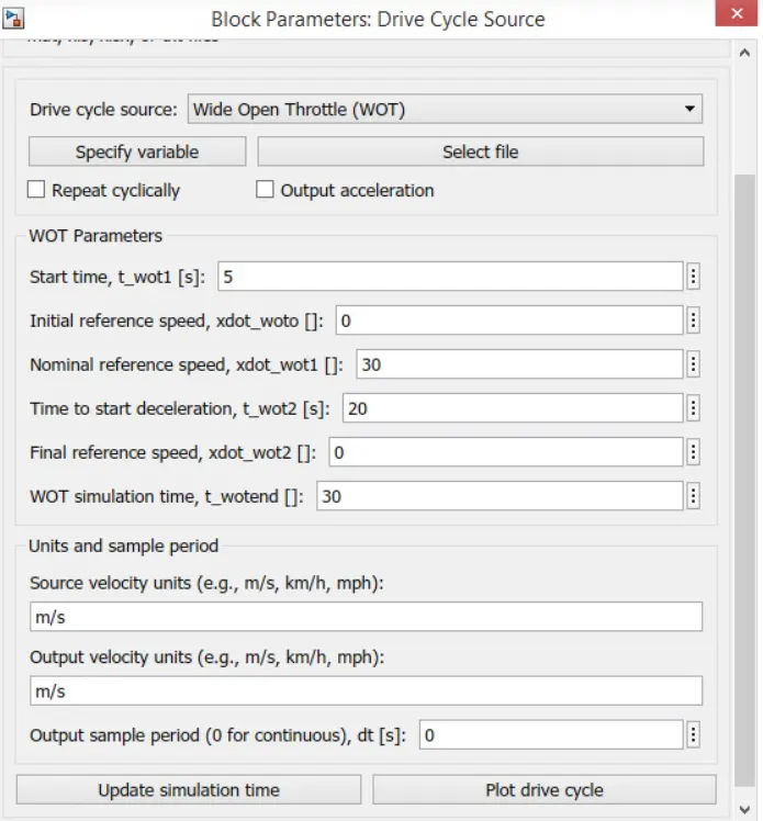
By default the drive cycle is set to FTP75 , which we can change by double clicking it.
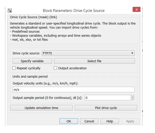
we choose the WOT cycle and modify the parameters.
Battery-
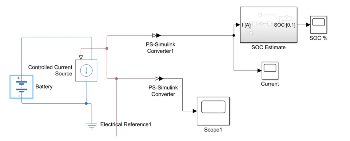
The battery is connected to the power source of the model,so that the power could be generated and the same power is transmitted accordingly.
The complete battery pack is -
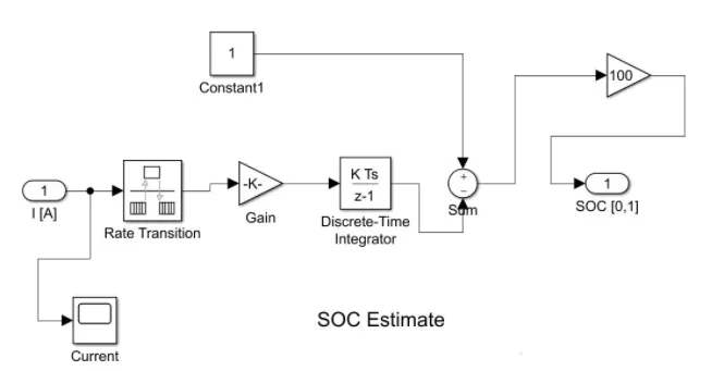
The SOC estimate block is -
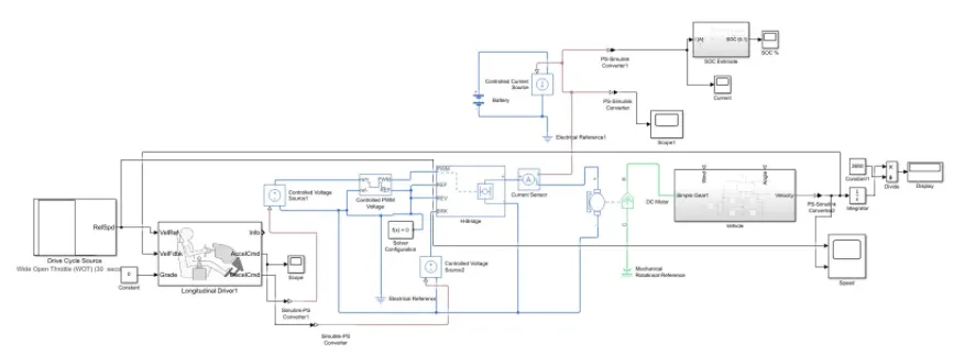
The final model after complete assembly-
OUTPUT-
1.Velocity feed back and drive cycle source-
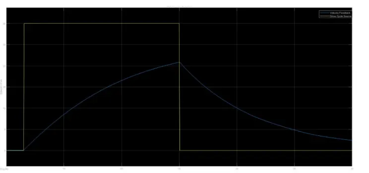
As represented on the plot given above the yellow curve shows the drive cycle data, as we know that the WOT (Wide Open Throttle) Drive cycle operates on the full throttle for some seconds and then the drive cycle is turned to 0 this in case operates the vehicle and accelerates the car at the top speed for the initial stage and throtles the car at the maximum, though the vehicle is unable to match the speed of the vehicle with the drive cycle but it is running at its peak and then cormes the phase where the acceleration is left now the vehicle is operated on the free wheeling mode, the vehicle is not powered and the vehicle runs on the speed which is sustained. The important point to note here is the vehicle does not come to rest in 60 seconds, the vehicles speed is reduced but it does not come to 0. The vehicle is operated as per the battery specifications as mentioned above on the specifications, the battery voltage supplied as the major source is 300 V and the motor used is the DC Motor in the overall operation the efficiency is been measured and as the operation of the cycle is operated at a specified duration of the WOT the same is been experienced. The overall distance travelled by the vehicle is 0.6 kms in a duration of 60 seconds.
2. Battery SOC Scope-
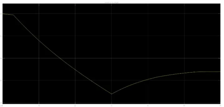
It is noted that the the Charge of the battery started from 100% at the initial level and during the operation of the vehicle for 60 seconds using the WOT Drive Cycle which has its peak throttle after the initial range the discharge occured / noted from the battery are until the high throttle was applied and it was been accelerated the battery got dishcharged at 97% and after the acceleration was been released the battery started recharging as the regenerative energy comes into action. The regenerative braking effectively charges the battery by 1% in the same duration where the vehicles acceleration pedal was been taken off and free wheeling.
Conclusion-
It is clearly visible that the vehicle could be simulated in the same manner and indifferent such simulations could be made to analyze the efficiency of the vehicle by keeping in consideration of the various parameters. These same simulations could be carried out before deciding the overall specification that the vehicle should achieve In this manner the Motor, Battery and other components could be chosen and then the actual model could be manufactured. There are chance of variation in the results which would be obtained in comparison of the Actual and Matlab Simulations as atual conditions would vary the results. All components could be customized as per the test which has to be carried out, like the vehicle mass, the vehicle battery specification the battery Motor and all others. As we analyzed in the test carried out above the vehicle has successfully achived the speed of 25 m / s and the vehicle covered a distance of 0.6 kms the same would differ once the vehicle parameters are varied.