Final Project: Design of an Electric Vehicle
OBJECTIVE-
Create a MATLAB model of electric car which uses lithium-ion . Choose suitable blocks from Powertrain block set. Prepare a report about your model including following:
1. System level configurations
2. Model parameters
3. Results
4. Conclusion
TITLE- Electric Vehicle Model Design Using SIMULINK in MATLAB
ABSTRACTS-
This project presents the simulation of a basic electric vehicle motor-drive system that is used to investigate power flow during both motoring and regeneration based upon a perticulae drive cycle data. The simulation assumes a DC brushless motor, an ideal H-Bridge motor controller combined with a controlled PWM voltage, and the electric vehicle battery. The model can be used to evaluate the electric drive’s
energy flow and efficiency for specific speed and torque load conditions. Some of the key system parameters were specified and others were modeled as ideal. A stable MATLAB/Simulink model was developed and validated. It was then used to determine the system performance and energy flow over a given set of motoring and regeneration speed/torque conditions.
INTRODUCTION-
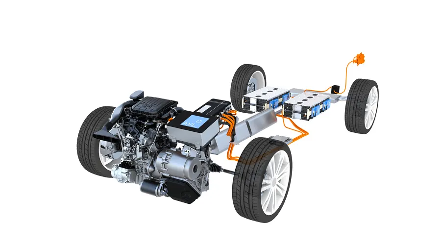
An electric car is an automobile that is propelled by one or more electric motors, using energy stored in rechargable batteries. Around 1832, Robert Anderson develops the first crude electric vehicle, but it isn't until the 1870s or later that electric cars become practical.
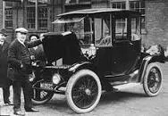
Pictured here is an electric vehicle built by an English inventor in 1884. Electric cars were popular in the late 19th century and early 20th century, until advances in internal combustion engines, electric starters in particular, and mass production of cheaper petrol (gasoline) and diesel vehicles led to a decline in the use of electric drive vehicle. The emergence of metal-oxide-semiconductor (MOS) technology led to the development of modern electric road vehicles. The MOSFET (MOS field-effect transistor, or MOS transistor), invented by Mohamed M. Atalla and Dawon Kahng at Bell Labs in 1959, led to the development of the power MOSFET by Hitachi in 1969, and the single-chip microprocessor by Federico Faggin, Marcian Hoff, Masatoshi Shima and Stanley Mazor at Intel in 1971. The power MOSFET and the microcontroller, a type of single-chip microprocessor, led to significant advances in electric automobile technology. MOSFET power converters allowed operation at much higher switching frequencies, made it easier to drive, reduced power losses, and significantly reduced prices, while single-chip microcontrollers could manage all aspects of the drive control and had the capacity for battery management. Another important technology that enabled modern highway-capable electric cars is the lithium-ion battery, invented by John Goodenough, Rachid Yazami and Akira Yoshino in the 1980s, which was responsible for the development of electric cars capable of long-distance travel. From 2008, a renaissance in electric vehicle manufacturing occurred due to advances in batteries, and the desire to reduce greenhouse gas emission and improve urban air quality. California electric automaker Tesla Motors began development in 2004 on what would become the Tesla Roadster (2008), which was first delivered to customers in 2008. The Mitsubishi i-MiEV, launched in 2009 in Japan, was the first highway legal series production electric car, and also the first all-electric car to sell more than 10,000 units. 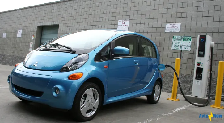
Tesla global sales passed 250,000 units in September 2017. The Renault–Nissan–Mitsubishi Alliance achieved the milestone of 500,000 electric vehicles sold in October 2017. Tesla sold its 200,000th Model S in the fourth quarter of 2017. 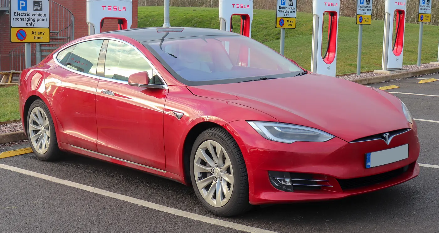
Global Leaf sales passed 300,000 units in January 2018, keeping its record as the world's top selling plug-in electric car ever. Tesla delivered its 100,000th Model 3 in October 2018.
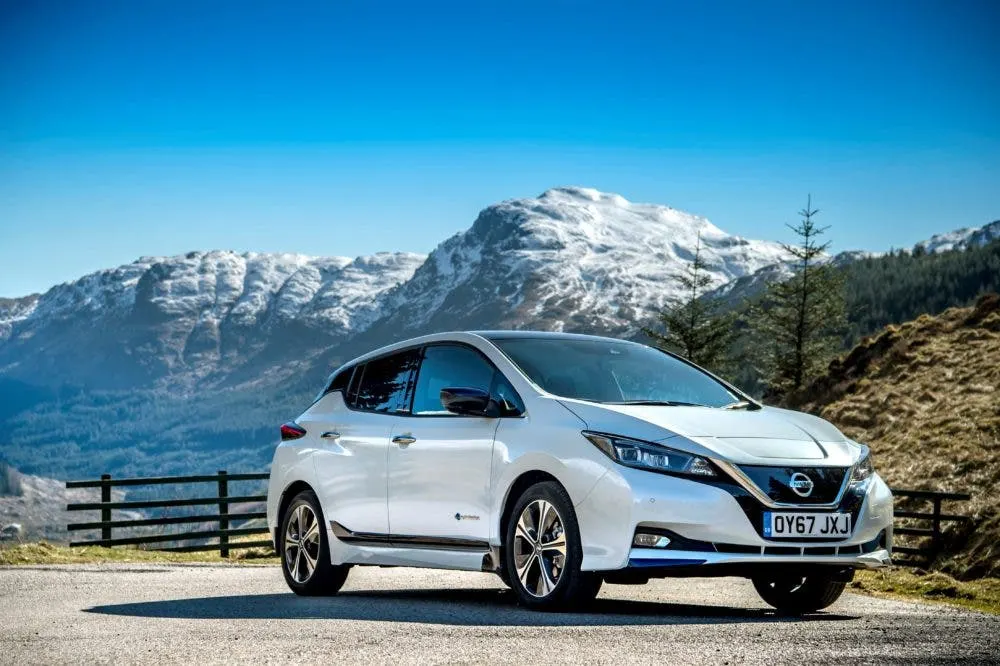
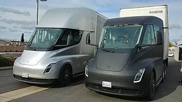
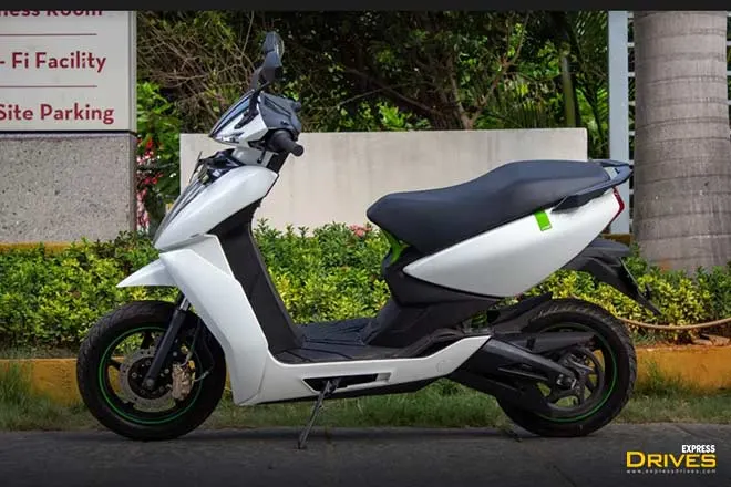
Besides many goods carrier truck, public transport bus, bikes and other types of electric vehicle sets a new record.
1.System Level Configurations-
MATLAB/SIMULINK MODEL>
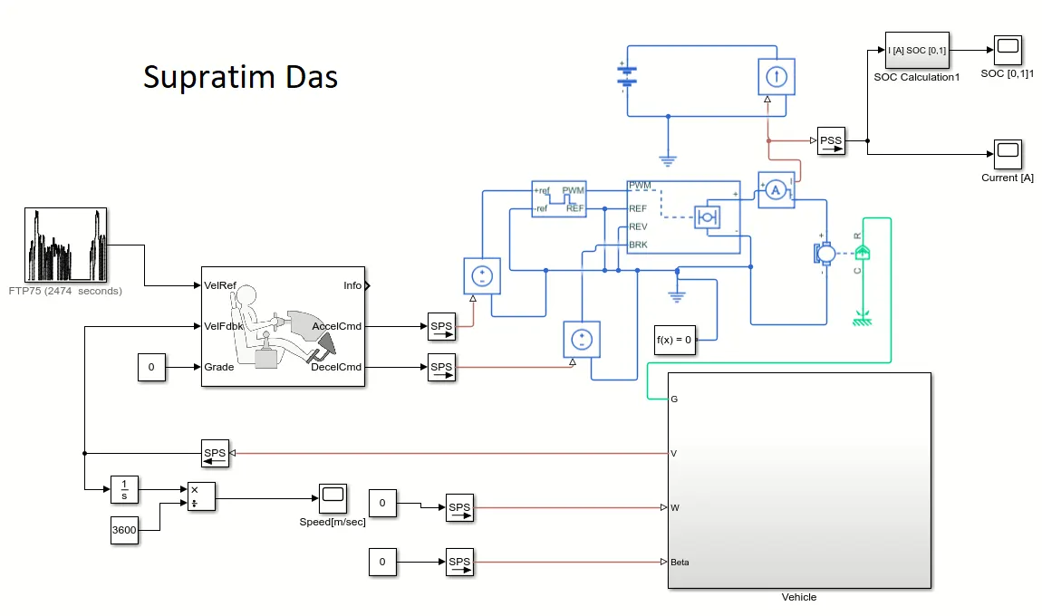
In this model I have designed a EV where it runs based on FTP75 drive cycle. It goes to Vehicle reference of Longitudinal driver block. Speed is taken as feedback through a Simulink-PS converter from Vehicle subsystem and given gradeability 0. For speed calculation a integrator block and a constant is connected with Divide block's positive and negative terminal respectively. Acceleration Command is given to Control Voltage source1 through a Simulink-PS Converter. The negative of Control voltage source1 is grounded. Then Decceleration command from Longitudinal driver is sends to another Control voltage source2 through a Simulink-PS converter. The negative of Control voltage source2 is grounded. Positive signal of the Control voltage source1 and Control voltage source2 sends to Controlled PWM voltage as positive reference and H-Bridge as braking command respectively. Negative reference of Control PWM voltage, Reverse of H-Bridge and both Reference output of Control PWM voltage and H-Bridge is grounded. A solver configuation is connected to the ground. Reference output of Control PWM voltage and H-Bridge is connected. Two output port of H-Bridge is connected to a DC motor's two terminal. Also the positive output of H-bridge is connected to a controlled courrent source through a current sensor. From the current sensor the current command is sends to the SOC block through a PS-Simulink coverter and to a current measuring scope. Positive and negative of the battery and controlled courrent source is conected and then negative is grounded. C port of the DC motor is attached with a mechanical rotational reference and R port torque is sends to the Gear box (G) of the vehicle subsystem. Constant blocks are connected to the Wind velocity(W) and Gradeability(Beta) ports through Simulink-PS converter.
VEHICLE SUB-SYSTEM>
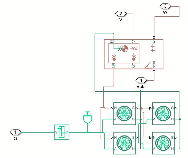
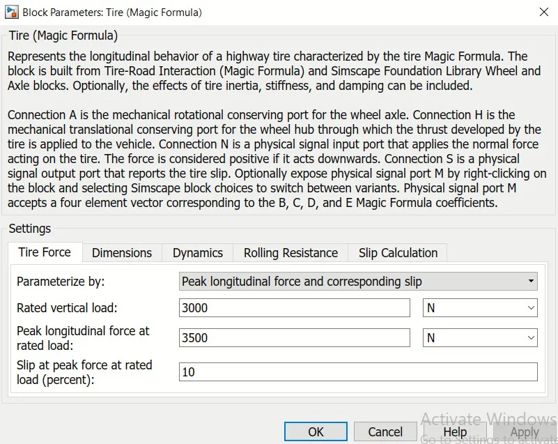
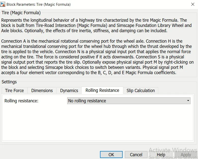
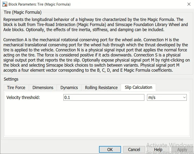
In this vehicle subsystem 4 tires(Magic formula) are used. In two groups Hub(H) and Axile(A) is connected of two tires for Rear and Front wheel. Hub of the two grops are connected and sends to the Hub(H) port of the Vehicle body. Rotation(N) of two wheels is connected for Rear wheel portion to NR and another two wheels is connected for Frontal wheel portion to NF of Vehicle body respectively. As the vehicle is rear wheel drive so connected axile of rear wheels is connected to a gear box. A inertia is added to it.
SOC CALCULATION SUB-SYSTEM>

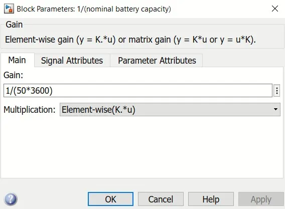
Rate Transition, gain and discrete-Time Integrator is connected in series and then connected Sum block's negative operator and constant to positive operator. Then the output of the sum is connected to SOC estimation scope.
Here all the blocks required to design this model is given in the list stated below>
| Block Name | Location | Number of Blocks |
Picture of the Block |
| Drive Cycle Source | Powertrain Blockset/Vehicle Scenario Builder | 1 | 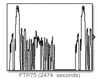 |
| Longitudinal Driver | Powertrain Blockset/Vehicle Scenario Builder | 1 | 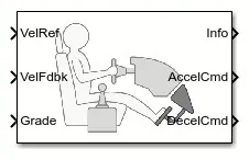 |
| Simulink-PS Converter | Utilities | 5 |  |
| PS-Simulink Converter | Utilities | 1 |  |
| Constant | Simulink/Sources | 5 |  |
| Controlled Voltage Source | Foundation Library/Electrical/Electrical Sources | 2 |  |
| Controlled PWM Voltage | Electronics/Actuators & Drivers/Drivers | 1 | 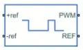 |
| H-Bridge | Electronics/Actuators & Drivers/Drivers | 1 | 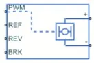 |
| Controlled Current Source | Foundation Library/Electrical/Electrical Sources | 1 |  |
| Current Sensor | Foundation Library/Electrical/Electrical Sources | 1 |  |
| DC Motor | Electronics/Actuators & Drivers/Rotational Actuators | 1 |  |
| Mechanical Rotational Reference |
Foundation Library/Mechanical/Rotational Elements | 1 |  |
| Scope | Simulink/Sinks | 3 |  |
| Battery | Electronics/Sources | 1 |  |
| Solver Configuration | Utilities | 1 |  |
| electrical Reference | Foundation Library/Electrical/Electrical Sources | 2 |  |
| Rate Transition | Simulink/Signal Attributes | 1 |  |
| Gain | Simulink/Math Operations | 1 |  |
| Divide | Simulink/Math Operations | 1 |  |
| Integrator | Simulink/Continuous | 1 |  |
| Discrete-Time Integrator | Simulink/Discrete | 1 |  |
| Sum | Simulink/Math Operations | 1 |  |
| Inport | Simulink/Ports & Subsystems | 1 |  |
| Outport | Simulink/Ports & Subsystems | 1 |  |
| Vehicle Body | Driveline/Tire & Vehicles | 1 | 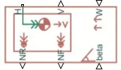 |
| Tire(Magic Formula) | Driveline/Tire & Vehicles | 4 | 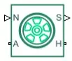 |
| Inertia | Foundation Library/Mechanical/Rotational Sources | 1 |  |
| Gear Box | Foundation Library/Mechanical/Mechanisms | 1 |  |
2. Model Parameters-
Drive Cycle>
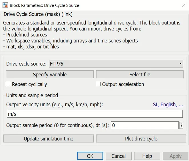
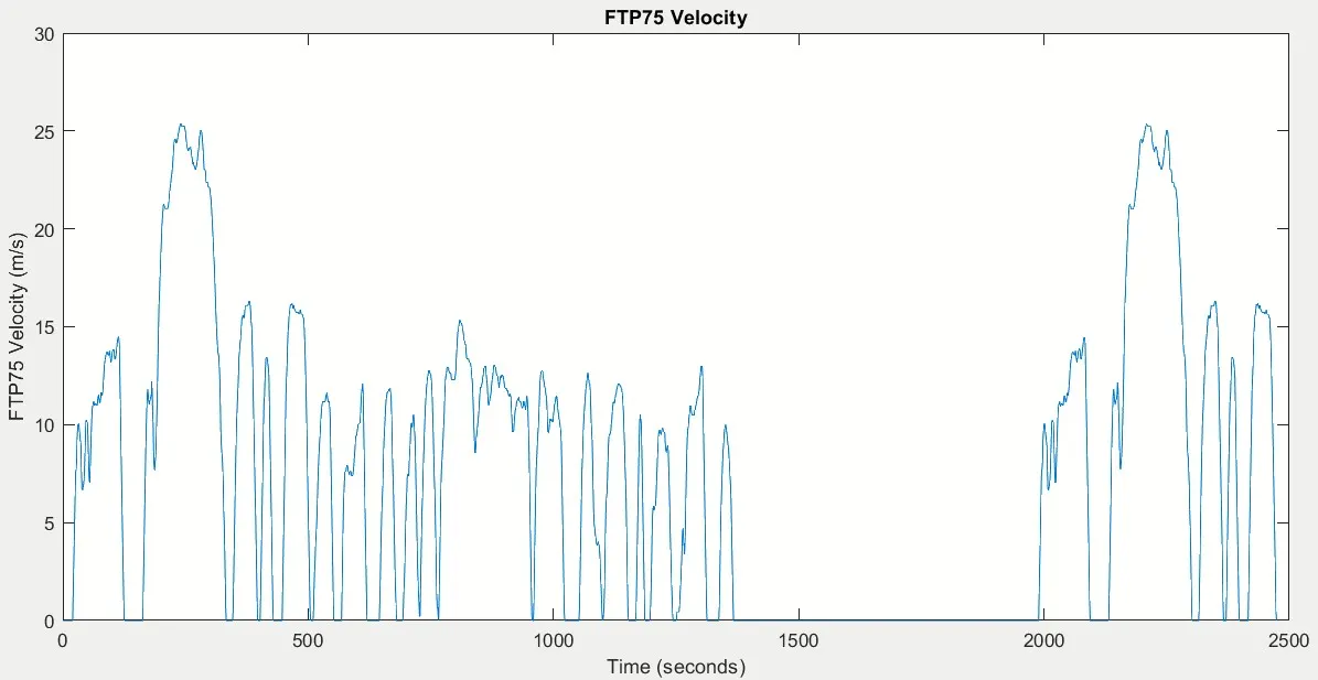
Here the FTP75 drive cycle data is provided for 2474 sec of time, where the maximum velocity is 26 m/sec.
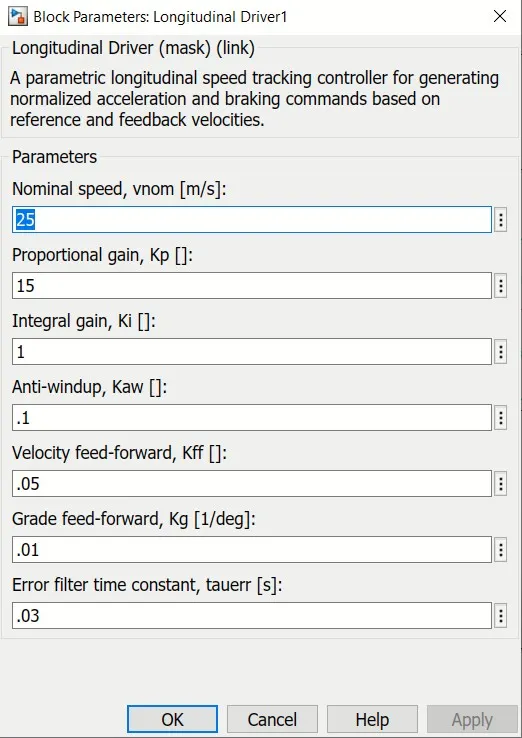
Longitudinal Driver Parameter>
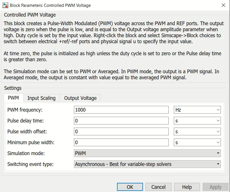
Controlled PWM Voltage>
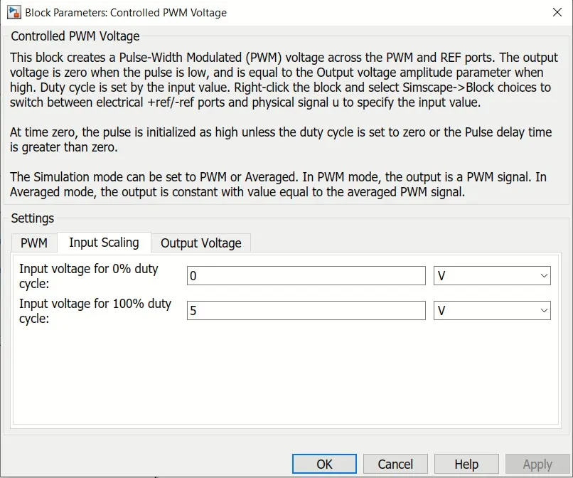
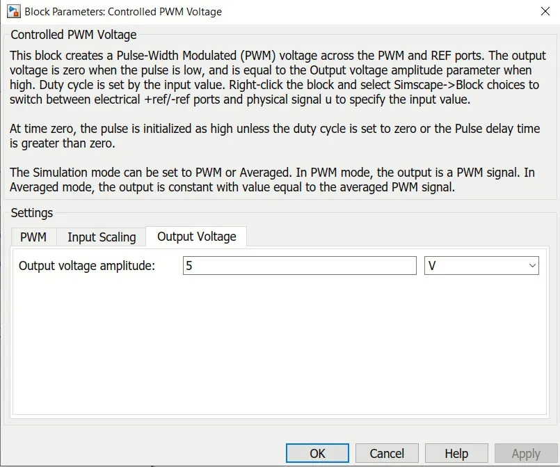
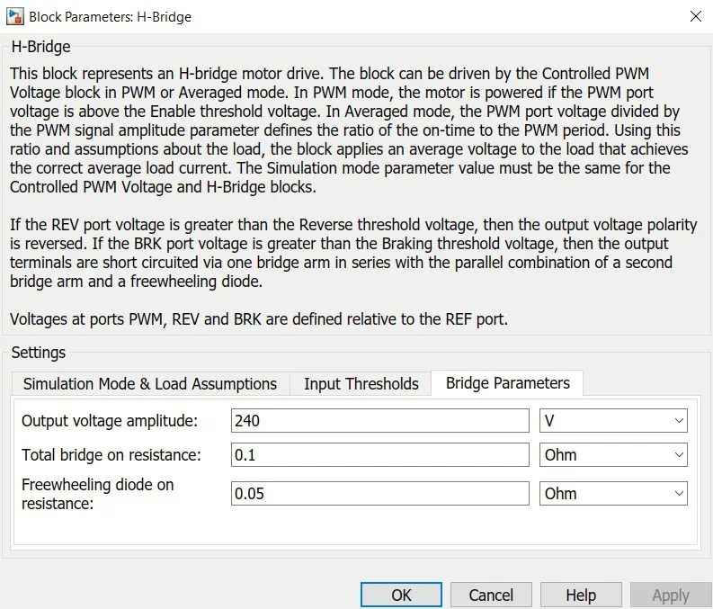
H-Bridge>
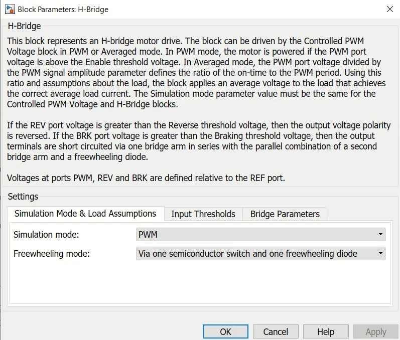
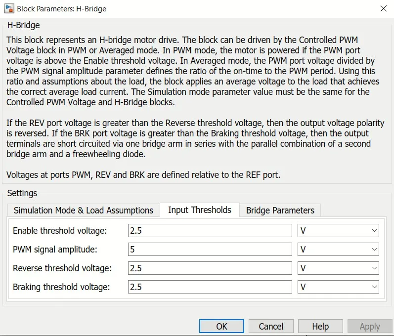
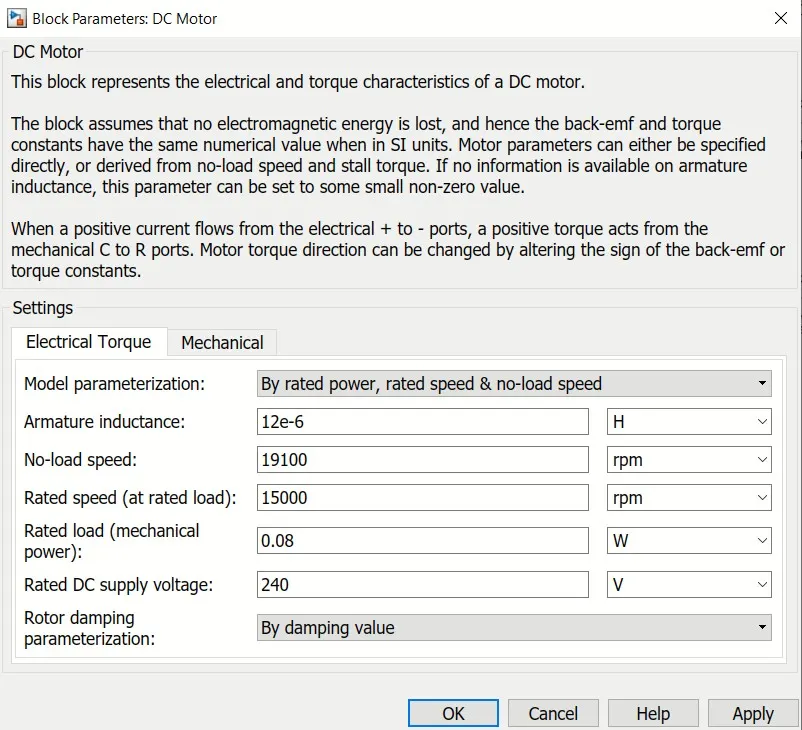
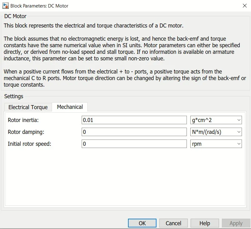
DC Motor>
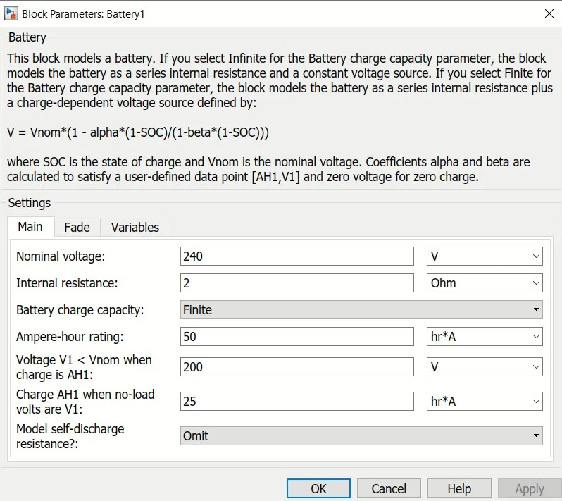
Battery>
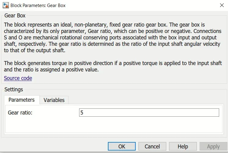
Gear Box>
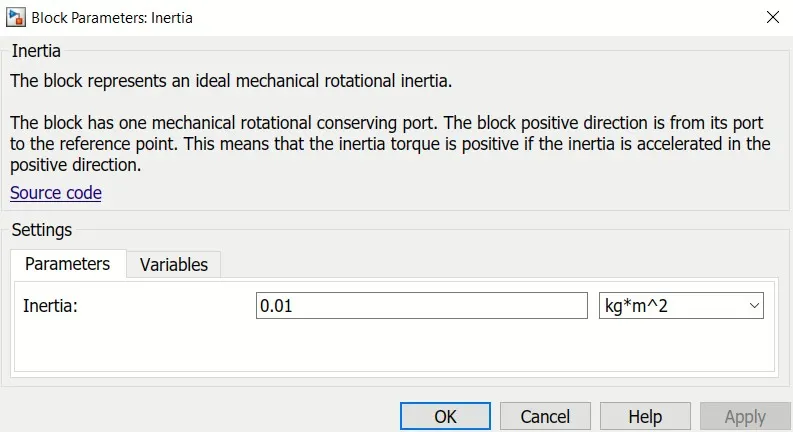
Inertia>
Tire(Magic Formula)>

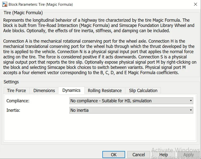
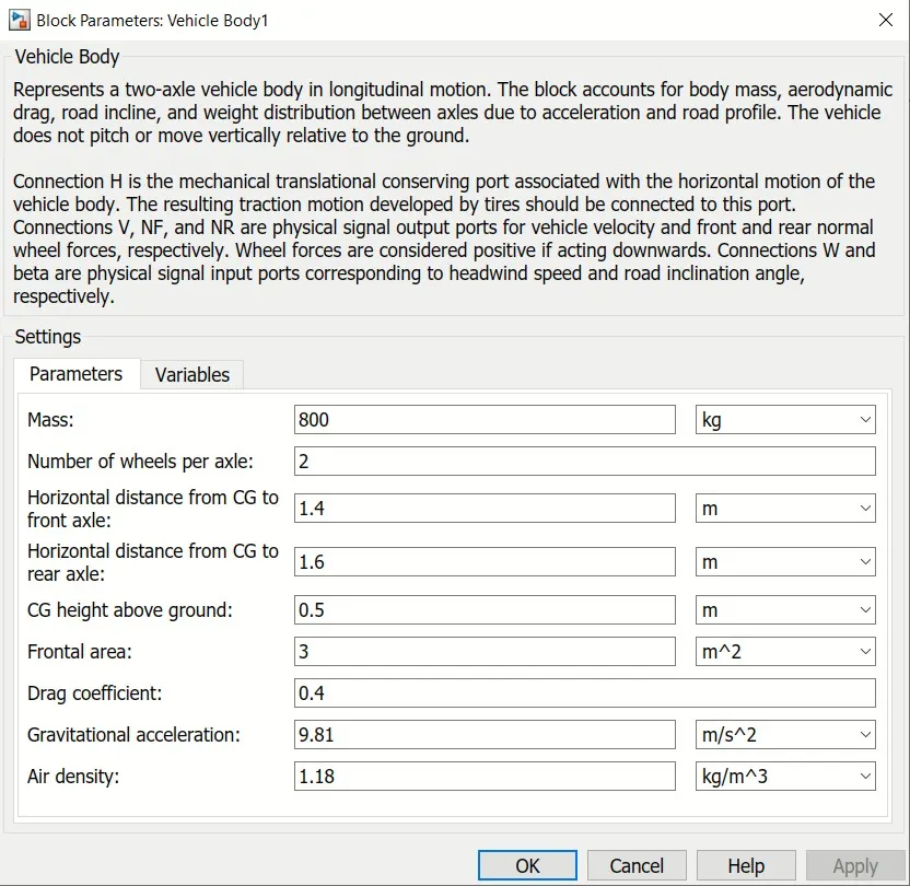
Vehicle Body>
Gain of SOC>
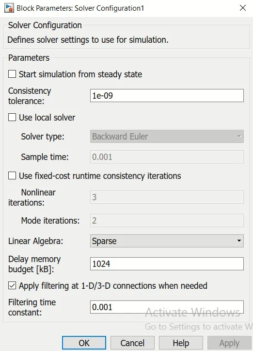
Solver Configuration>
3. Results-
SOC Estimation Scope-
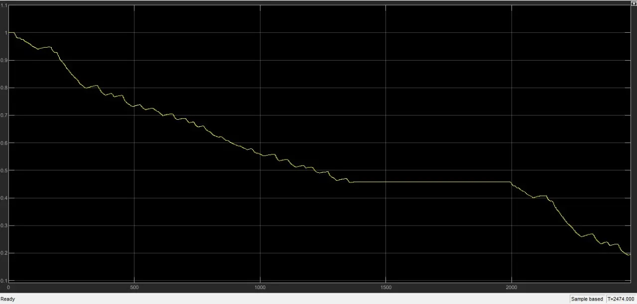
Here the simulation has done for 2474 sec. At the begining the the SOC was 100% and after 2474 sec of simulation the SOC decreased to 19%. Regenerative braking was taking place.
Current Scope-
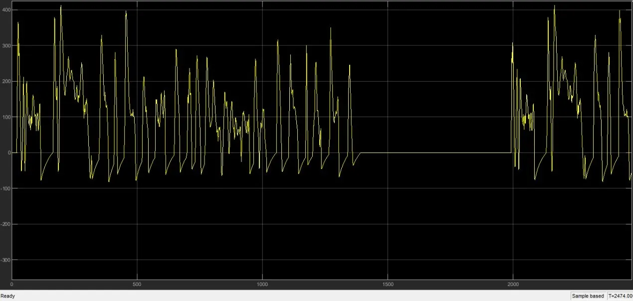
Based on the drive cycle data and other parameters the DC motor drawn current for acceleration and rotation to maintain the speed of the vehicle.
Speed Scope-
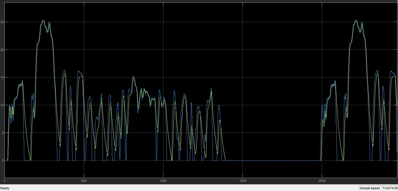
Here we can see two different colour line is overlaping each other in this plot. The blue line is the reference speed as per the drive cycle and the yellow line is the actual speed of the vehicle that has taken for feedback. The maximum actual speed is 25 m/sec.
4. Conclusion-
This simulation has done on Matlab 2017b based on the above stated parameters. This parameters can be changed. We can change the motor type, motor rating, controller rating, battery type and rating, drive cycle etc. Based on those prameters the simulation result of SOC estimation, Current, Speed will change accordingly. We can use use different battery from extra source directory and add other functions like temperature sensor. As this is a pure EV, we can also make hybrid EV and add other function for simultaneously changing the operations of IC Engine and Motor.
Link for EV model which is elaborated above: EV Model
For this project I thanks Sathya Balasubramanian for helping me to get a solid idea and clarifying my all doubts.