FINAL INDEPENDENT PROJECT
Title: Project Report 3D Modeling of a Small Flight in SolidWorks
Objective:
The primary objective of this project is to showcase the 3D modeling process of a small flight using SolidWorks. The focus is on designing and simulating a miniature aircraft to demonstrate SolidWorks' capabilities in aerospace modeling.
Introduction:
The design and modeling of a small flight in SolidWorks involve creating a detailed and realistic representation of a miniature aircraft. This project aims to highlight the steps involved in the 3D modeling process, emphasizing accuracy, aerodynamics, and functionality.
Design Methodology/Approach:
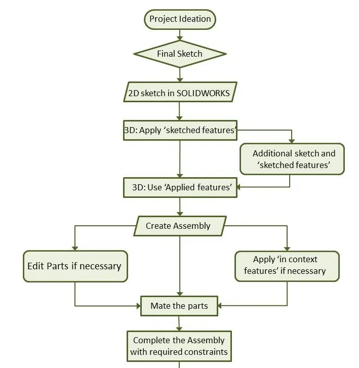
The design process follows a systematic approach, utilizing SolidWorks' versatile toolset. The flowchart below outlines the key steps involved in the design methodology:
Description:
Detailed descriptions of the modeling process for the small flight:
1. Define Aircraft Specifications:
Design Overview: Establish the specifications for the small flight, including wingspan, fuselage length, tail design, and other aerodynamic features.
Modeling Process: SolidWorks' sketching tools are used to create a 2D profile of the aircraft, defining key dimensions and proportions.
2. Sketching and Extrusion:
Design Overview: Develop the 3D shape of the aircraft by extruding the initial sketches to create the main body and wings.
Modeling Process: Utilize SolidWorks' sketching and extrusion tools to transform the 2D profile into a 3D model.
3. Wing Design and Surface Features:
Design Overview: Enhance the wings with airfoil profiles, winglets, and other surface features to improve aerodynamics.
Modeling Process: Employ SolidWorks' surface modeling tools to refine the wing's shape and add aerodynamic elements.
4. Tail and Control Surfaces:
Design Overview: Model the tail section and control surfaces, including elevators and rudders, to ensure stability and control.
Modeling Process: Use SolidWorks' sketching and feature tools to create the tail section and control surfaces.
5. Fuselage and Cockpit:
Design Overview: Design the fuselage and cockpit for the small flight, considering aerodynamics and pilot accommodation.
Modeling Process: Apply SolidWorks' lofting and extrusion features to create a streamlined fuselage with a detailed cockpit.
6. Assembly and Motion Analysis:
Design Overview: Assemble all components and conduct motion analysis to evaluate the aircraft's behavior.
Modeling Process: Use SolidWorks' assembly features to bring together individual parts, applying mates and constraints for realistic movement.
Screenshots:
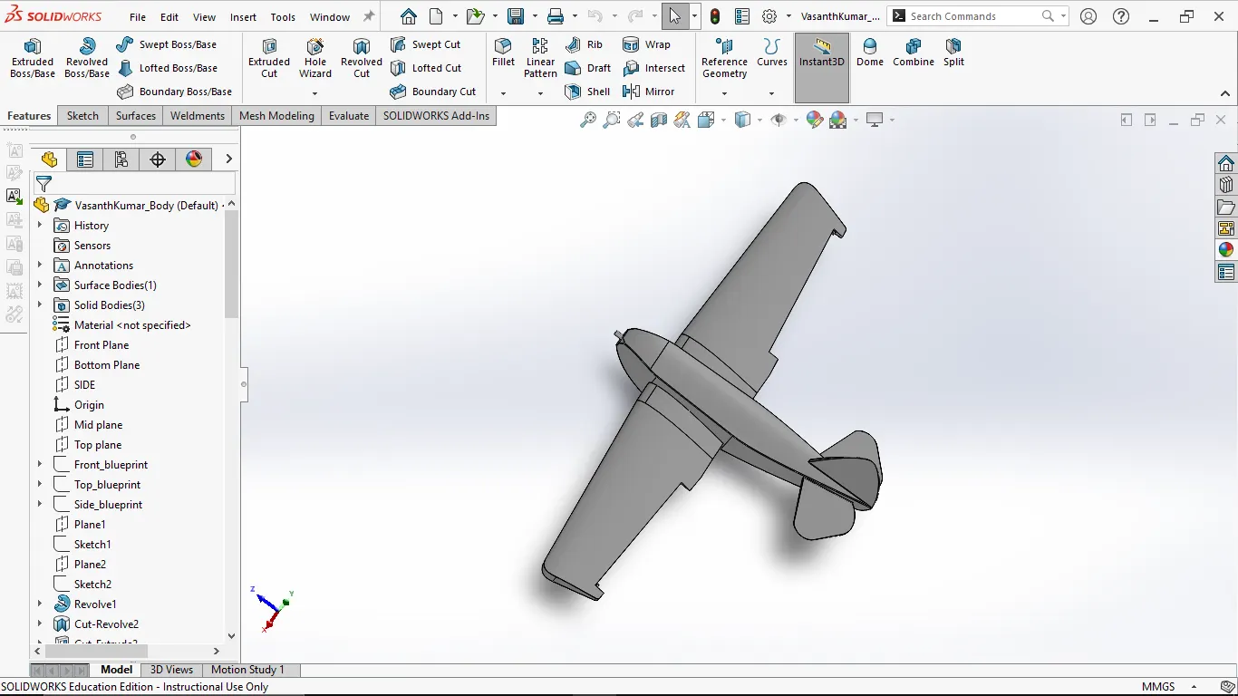
1.Fuselage:
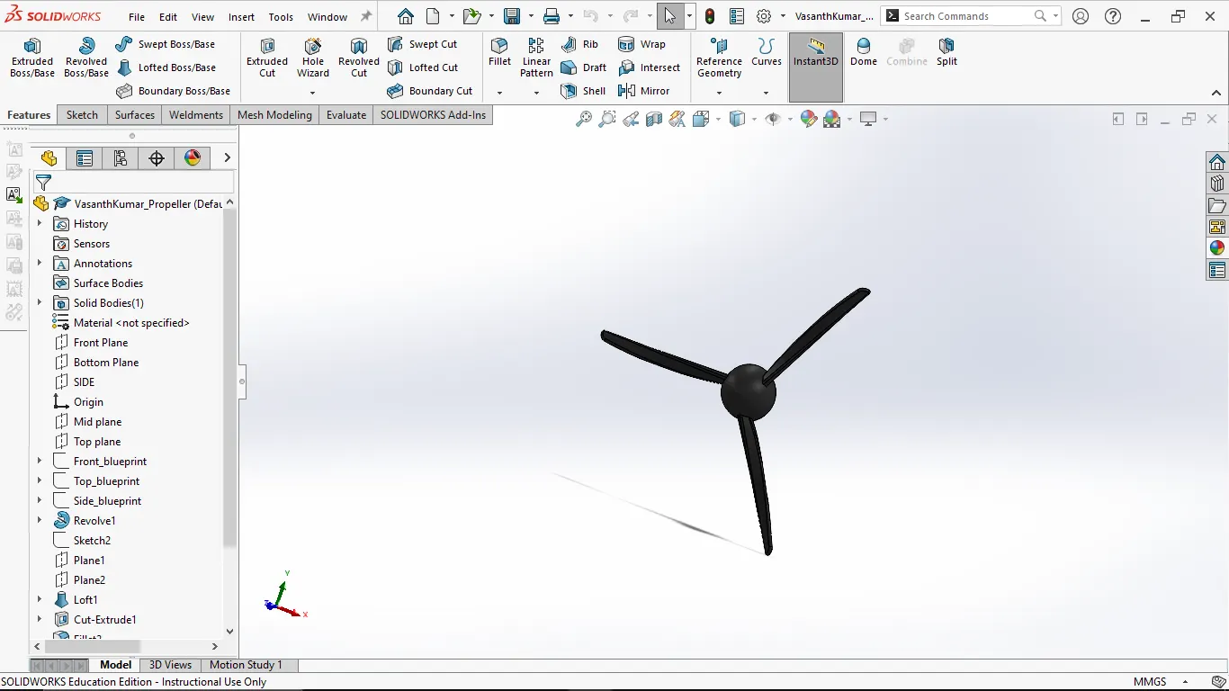
2.Propeller:
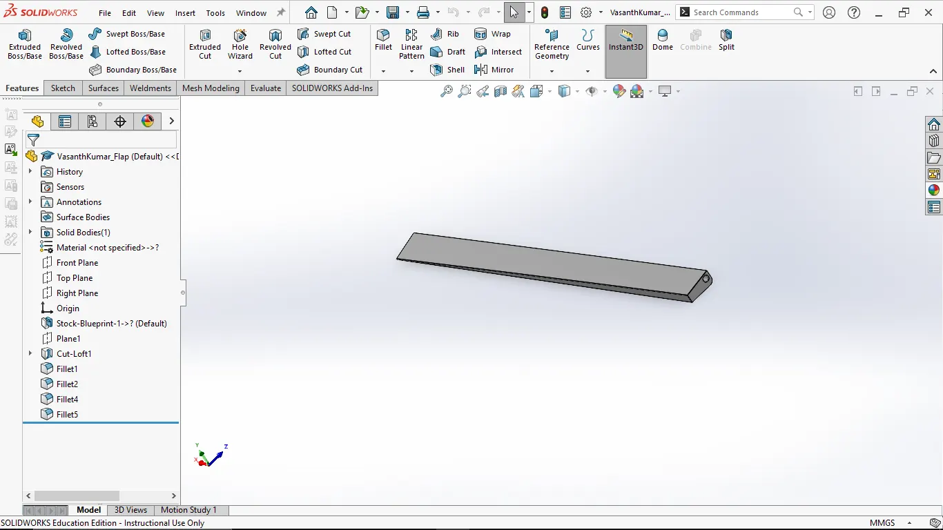
3.Flap:
4.Cockpit:
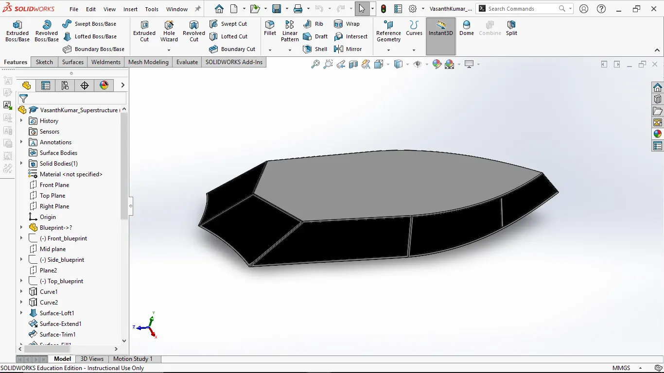
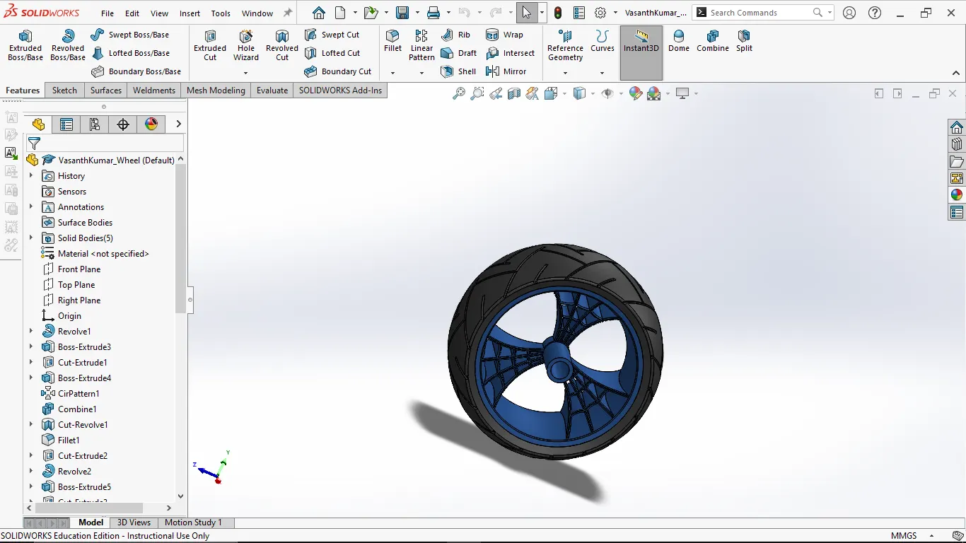
5.wheel:
Conclusion:
The 3D modeling project for the small flight in SolidWorks has been successfully executed, showcasing the design and simulation of a miniature aircraft. The design methodology, as illustrated in the flowchart, ensures a systematic approach to modeling. The detailed screenshots provide a visual representation of the intricacies of the small flight, emphasizing accuracy and realism. This project demonstrates SolidWorks' capabilities in aerospace modeling, offering a versatile platform for designing and simulating aircraft components.
Part file link : Gdrive