FINAL INDEPENDENT PROJECT
PROJECT TITLE : Wheel Loader.
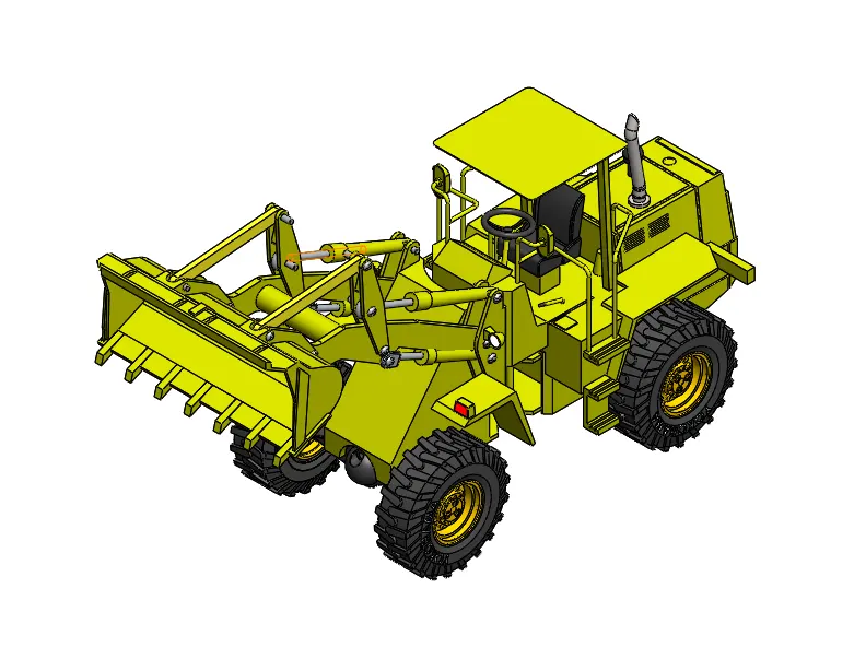
Isometric veiw:
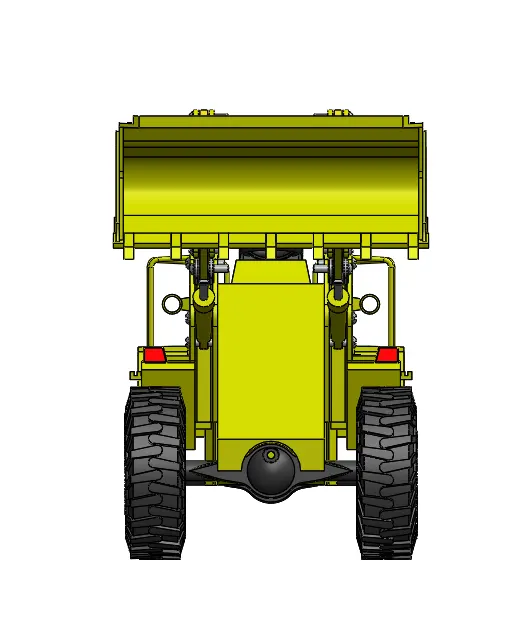
Front veiw:
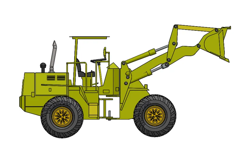
Left veiw:
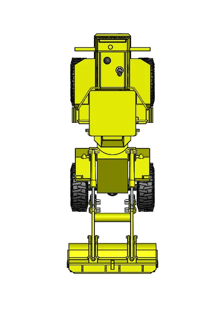
Top veiw:
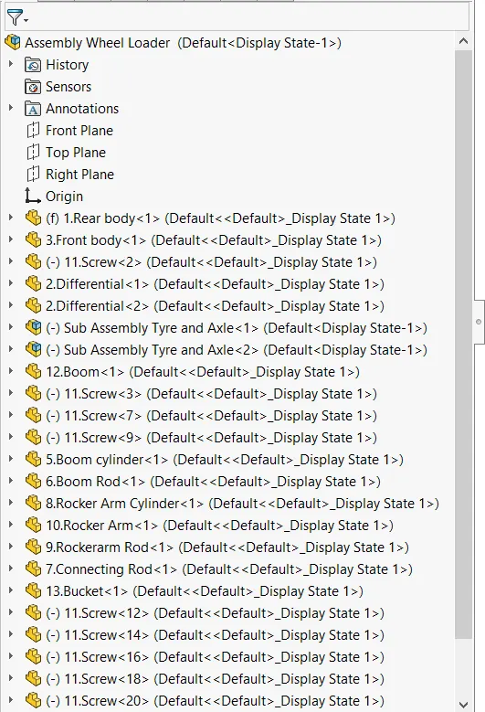
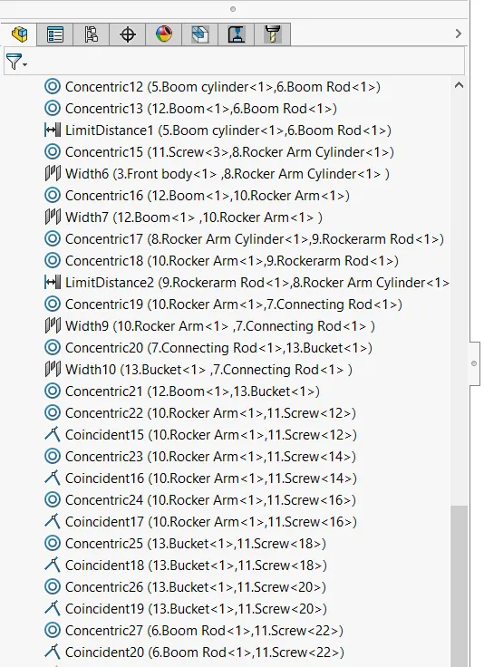
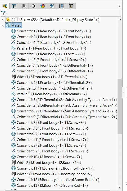
Wheel loader Tree:
OBJECTIVES:
1.To model and assemble Wheel loader in SOLIDWORKS.
2.To understand how to use all the properties in SOLIDWORKS.
3.To know how to do rendering for the perfect outcome.
INTRODUCTION:
Wheel loader which made of different characteristic features like fillet, extrude, chamfer, swept, cut extrude, and more others.
We have different components which are drawn separately with each other.
After designing all parts, we assemble the model and then we do render to complete our design with the best outcome.
COMPONENTS:
1.Rear body
2.Front body
3.Screw
4.Differential
5.Axle rod
6.Boom
7.Boom cylinder
8.Boom rod
9.Rocker Arm
10.Rocker Arm cylinder
11.Rocker Arm rod
12.Connecting rod
13.Rim & Tyre
14.Bucket
15.Sub Assembly Tyre
DESCRIPTION:
1.Rear body :
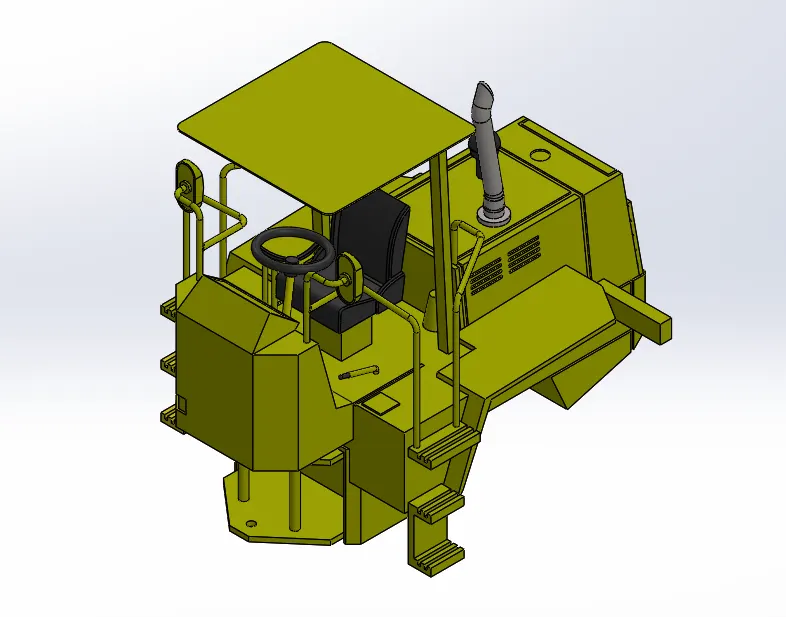
Rear body is main body of the wheel Loader.which gives support to the vehicle and it holds all parts of the vehicle. It contains several parts such as Engine,Exhust,Airfilter,Sreering wheel,Mirrors,Driving seat,Rear wheels and etc.
- Boss extrude
- Cut extrude
- Chamfer
- Linear pattern
- Fillet
- Draft
- Sweep
- Mirror
- Revolve
- Dome
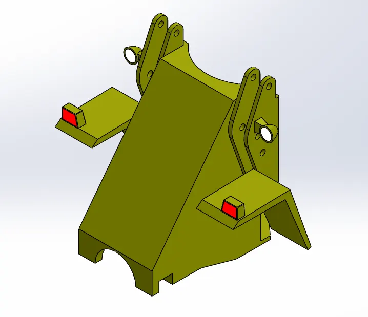
2.Front body :
It is located at front of the vehicle.Front body and Rear body connects with the help of Screw eachother and it is mounted on front wheels of the vehicle.It holds the diffrential and linkage mehanism.
- Boss extrude
- Cut extrude
- Fillet
- Draft
- Rvolve
- Dome
- Split line
- Combine
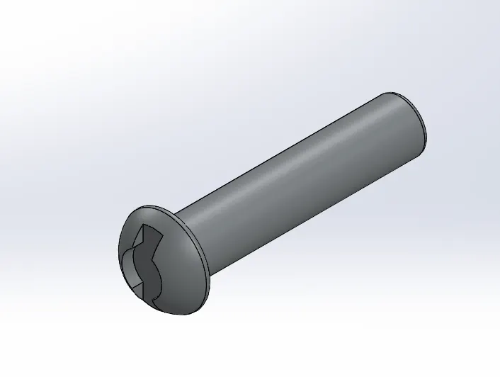
3.Screw :
Screws are to hold links together and to position links in proper way.
- Revolve
- Cut extrude
- Fillet
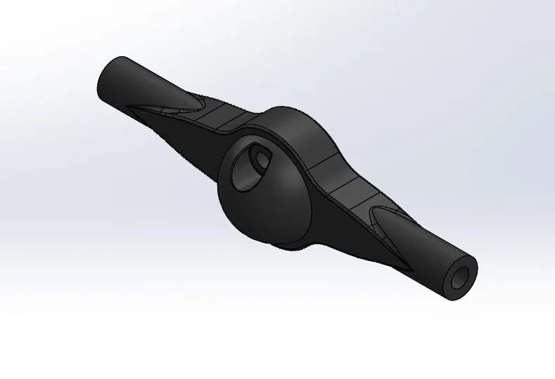
4.Diffrential :
Diffrential is a driver mechanism which transfers the torque to the wheels through the axil. Two diffrentials are used in the modeling of the wheel loader. One is placed at the rear wheel axil and another one is placed at front wheels .
- Boss extrude
- Fillet
- Cut extrude
- Split
- Mirror
- Dome
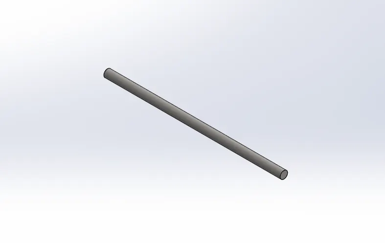
5.Axil rod :
It transmits the power to the wheels through the diffrential. It connects the wheels of the vehicle.
- Boss extrude
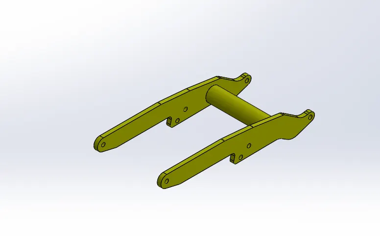
6.Boom :
Boom is the long part of wheel loader .it is connected to the vehicle's Front body and the Bucket with the help of screw.It holds the bucket.
- Boss extrude
- Cut extrude
- fillet
7.Boom Cylinder :
It is used to operate the movement of boom link up and down withe help of hydtaulics.one end of the cylinder is attached at bottom of the front body and another end Boom rod is fixed to the cylinder.
- Boss extrude
- Revolve cut
- Cut extrude
- Fillet
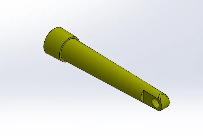
8.Boom rod :
It is the part which connects the Boom cylinder to the Boom link.
- Boss extrude
- Cut extrude
- Fillet
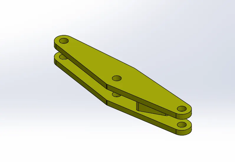
9.Rocker arm :
Rocker arm is a main and center link . Boom link, Connecting rod & Rocker cylinder system connected to the Rocker arm.
- Boss extrude
- Cut extrude
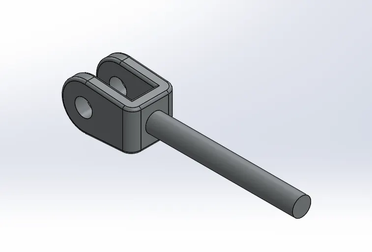
10.Rocker cyllender :
It is bigger than Boom cylinder . one end of rocker cylinder attached to the front body of vehicle and second end fixed to the rocker rod. It controls the movement of the Bucket.
- Boss extrude
- Revolve cut
- Cut extrude
- Fillet
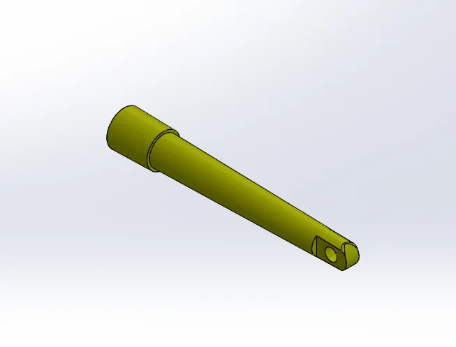
11.Rocker rod :
It is the part which connects the Rocker cylinder and thr Rocker arm.
- Boss extrude
- Revolve
- Dome
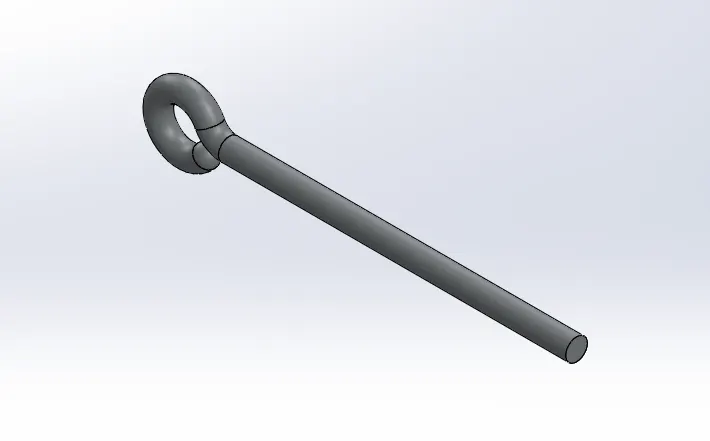
12.Connecting rod :
It is the link which connects the Rocker arm and the Bucket.
- Boss extrude
- Cut extrude
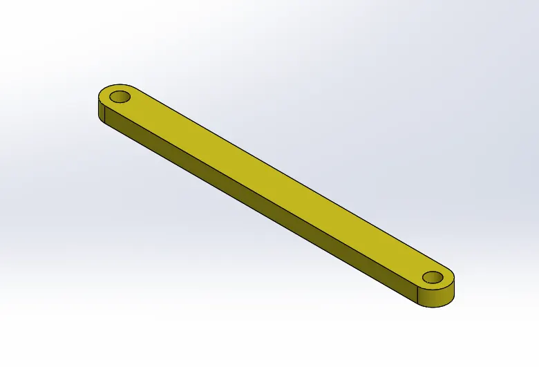
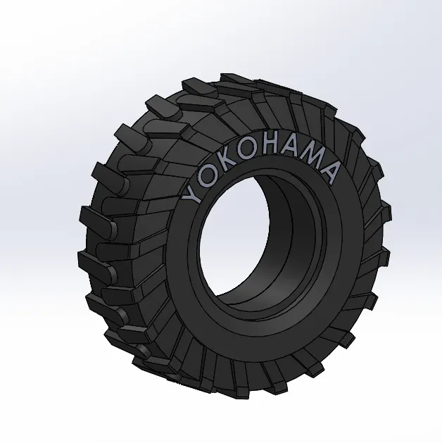
13 Rim & Tyre :
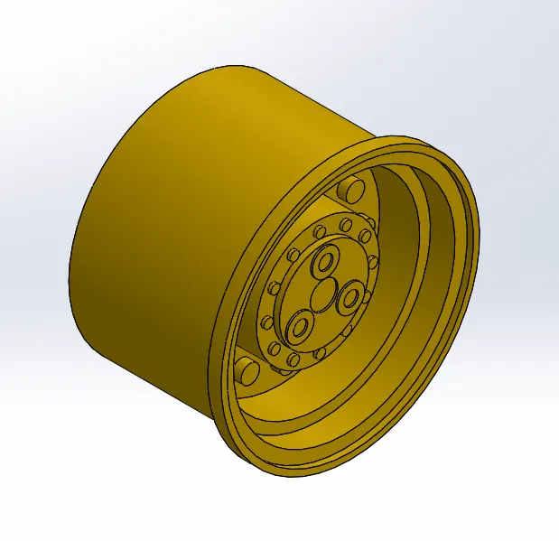
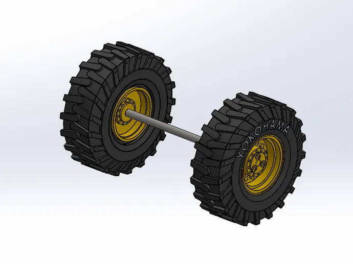
Wheels include the Tyre and Rim. wheels are attached to the axil rod.
- Revolve
- Boss extrude
- Split line
- Offset surface
- Boundary boss/base
- Circular pattern
- Body move
14. Bucket :
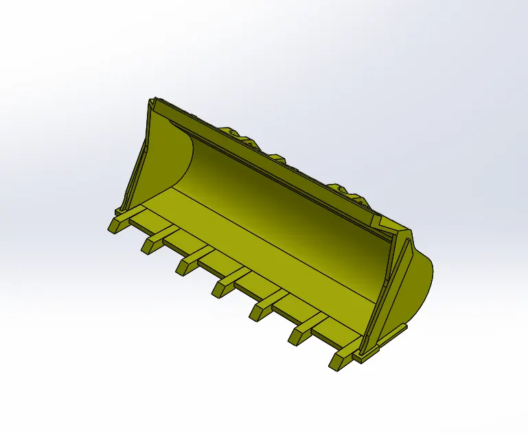
Bucket is the final part of the Wheel loader and is the part scoops the earth.it is attached to the connecting rod and whih the Boom.
- Boss extrude
- Fillet
- Cut extrude
- Chamfer
- Shell
- Combine
- Mirror
15.Sub Assembly Tyre :
Rendered Wheel loader :
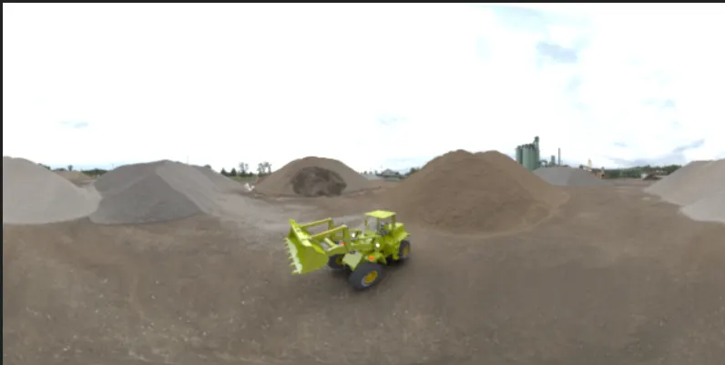
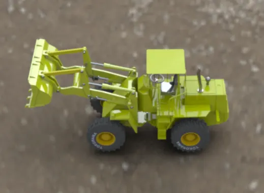
- Rendering is the process of creating realistic images of the model we created with the enviromment setup.By using Photoview360 or Solidworks visulize render the Photorealistic models to realistic images.
- photo realistic Wheel loader model is rendered into realistic images in diffrent views.
Conclusion :
All parts of Wheel loader is modeled and assembled together successfully and rendered into realistic images of the model created by using rendering tools.