Fender Design - Wheel Arch Challenge
FENDER- Fender is a part of an automobile, motorcycle or other vehicle body that frames a wheel well(underside). Its primary purpose is to prevent sand,mud,ricks,and other road spray from being thrown into the air by the roating tire. Fenders are typically rigid and can be damaged by contact with the road surface. The main purpose of fenders on cars is that they shield the wheels and they protect the passengers,the pedestrians, and the other vehicles from stones, mud, liquid,and other debris that van fly in the air because of the speeding roatating wheels while the car is running.

Types of fender- The type of fender is based upon the area covered i.e., full fender type and half fender type.
Full fender type:- Full fender type is traditional type of fender where more material consumption is oberved. This type is used in old design of automobiles where it increase the overall weight and thus reduce performance. The maintance also relatively more due to more surface. 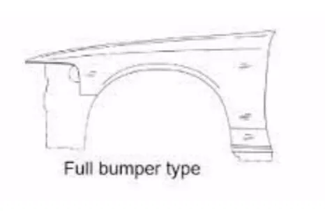
Half fender type:- Half fender type is modern design where less material consumption is oberved, so productivitity increase by reducing size of blank and thus providing more performance. The maintance also relatively low compared to full bumper type. 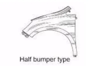 Wheel Arch- It is a curved part of the fender positioned right above the wheel. The wheel arc is designed such that it protects both the pedestrian and car cabin from mud,water rocks and other road spray. Different countries have different wheel arc regulations in place, and wheel arch design has to comply with them to be deemed usable in that country.For avoiding design alterations of the same vehicle to meet the different regulations in different countries, the maxium values of the concerned regulation parameters are taken into consideraton for design purpose.
FENDER WHEEL ARC AREA REGULATIONS
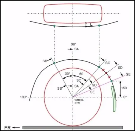
Wheel Arc Area has some standard specifications. If you see the car from the front, and the wheel is outside of the fender, it will make more chipping. As a result, it can produce damage to pedestrians and other cars. To keep pedestrian safety, we will have to position the tire wheel inside the fender as shown in top view.
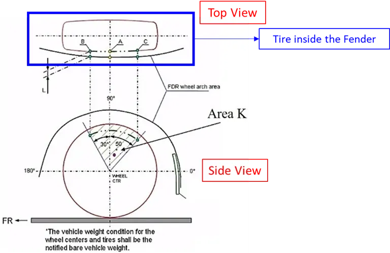
For every region in the globe, there will be different regulations for the wheel arc requirement. The reason why these requirements change from region to region is because these are fixed with respect to each region road conditions. So, once you get the fender styling data (data produced from wheel data), take the wheel center, and build and mark 0 to 180°. The next steps of this study depend on specific region requirement.
Japan Regulation Requirement
The study for Japan regulations consists of the following steps:
- Define the wheel center.
- Create a perpendicular line. The point projected from side view to top view will be A.
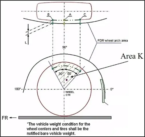
- Take the 50° right and 30° left of the car and project the points from side view to top view (B and C).
- When the region created is projected from the side view to the top view, you allow to have a gap of minimum 5 mm. The Japan’s government through its regulation team is who determines that 5 mm value.
- Measure clearance L of tire, hub, cap, and fender in 3 different positions within area K and produce clearance check chart to validate.
- All these points should have minimum clearance of 5 mm. Clearance must be greater than 5 mm in all the 3 positions.
- Wheel Guard Requirement: The value of ‘a’ shall be more than 5 mm at a line 30° forward and 50° rearward from the central vertical axis of wheel’s axis.
We will have to do this study and see if the fender is matching. If this is not matching, we should go with the styling team and ask them again to change the curvature of the fender. This procedure should be followed up to we get the 5 mm gap requirement.
European Regulation Requirement
The study for European regulations consists of the following steps:
- Take the Wheel Center.
- Mark the 30° line (SB) and the 50° line (SC). Same way it was done for Japan.
- But additionally, we have to take additional points:
- Take a point at 150 mm from the zero and mark the line (SE).
- Mark the midpoint between the points SC (50°) and SE (150 mm). → SD
- At the end, confirm that under all these 5 sections, the Clearance Length should be 10 mm or greater to satisfy the European regulations.
- Measure Clearance Length value at sections (SA-SA, SB-SB, SC-SC, SD-SD, and SE-SE).
- Produce a Clearance Check Chart to validate.
- Wheel Guard Requirement: The value of ‘a’ shall be more than 5 mm at a line 30° forward and 50° rearward from the central vertical axis of wheel’s axis.
US Regulation Requirement
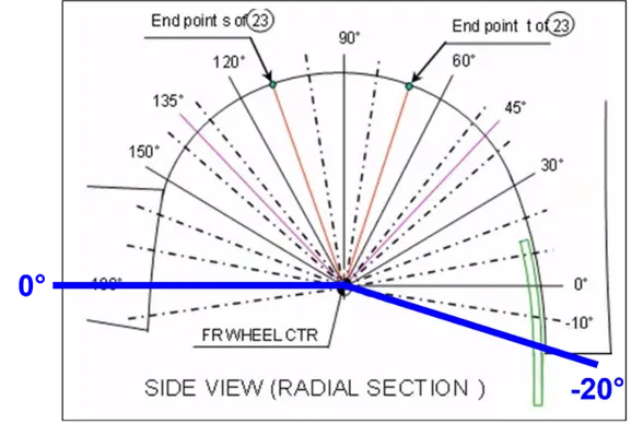
Similarly, US also have a regulation which says do the same concept for every 10° from -20° to 0°. When this is done, we should have 5 mm clearance from the length.
So, if the car is being prepared for different markets (for example, Japan, US, and Europe), we basically keep 10 mm clearance for all regions, so that all the requirements are satisfied.
The study for US regulations consists of the following steps:
- Make clearance check details on all positions from -100° to 100° and make the clearance check table.
- All values should be greater than 5 mm to satisfy the regulations.
- Wheel Guard Requirement: The value of ‘a’ shall be more than 5 mm at a line 30° forward and 50° rearward from the central vertical axis of wheel’s axis.
For a car that is addressed to various markets (for example, Japan, Europe, and also US), it is needed to take one major requirement that is the maximum clearance value for all these cases. The reason is because it is not allowed to prepare variations in the fender (we cannot have two different fenders for one model car). We have to take the maximum deviation value and use the same for all the cars.
WHEEL ARC GAP CALULATION AT THE REQUIRED 5 POINTS
To assess Wheel Arch Area, it is needed to calculate the gap at required points and check whether the car passes the European Standard.
1. Create a datum plane on the wheel outer section. Take the Wheel Center.
2. Mark a line from the wheel center to the constructed datum plane, and then follow the specified angles for SB and SC (Mark the 30° line for SB and the 50° line for SC), and distance for SE (point at 150 mm from the zero). Mark the intersection points between lines and projected curve.
3. The SD line is drawn in the middle of SC and SE line.
CLEARANCE CHECK CHART
At the end, it was checked all the 5 sections and the results were summarized in chart shown below. The Clearance Length requirement is 10 mm or greater to satisfy the European regulations.
|
Point |
Clearance Length (L) [mm] |
Result |
|
A |
10mm |
PASS |
|
B |
9.949mm |
FAIL |
|
C |
0.113mm |
FAIL |
|
D |
2.887mm |
FAIL |
|
E |
5.9973 |
FAIL |