Fender Design - Wheel Arch Challenge
AIM
To Calculate the Wheel Arc area and prove whether the car will pass the standards or Not.
FENDER
Fender is the American English term for the part of an automobile, motorcycle or other vehicle body that frames a wheel well (the fender underside). Its primary purpose is to prevent sand, mud, rocks, liquids, and other road spray from being thrown into the air by the rotating tire. Fenders are typically rigid and can be damaged by contact with the road surface.
Sticky materials, such as mud, may adhere to the smooth outer tire surface, while smooth loose objects, such as stones, can become temporarily embedded in the tread grooves as the tire rolls over the ground. These materials can be ejected from the surface of the tire at high velocity as the tire imparts kinetic energy to the attached objects. The fender not only protects your car from sustaining damage from road debris but it prevents this debris from being thrown up at other vehicles on the road. There are two types of fender such as Full Bumper Type and Half Bumper type.
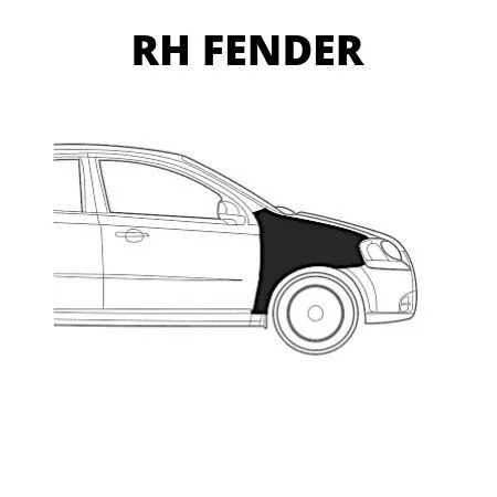
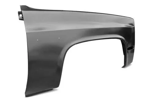
WHEEL ARCH
The wheel arch is the semicircular part positioned above the wheel of a vehicle. The most important body change was that the front wheel arch was cut higher into the fender. ... The car has big, high-definition headlights that extend to the wheel arch.
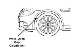
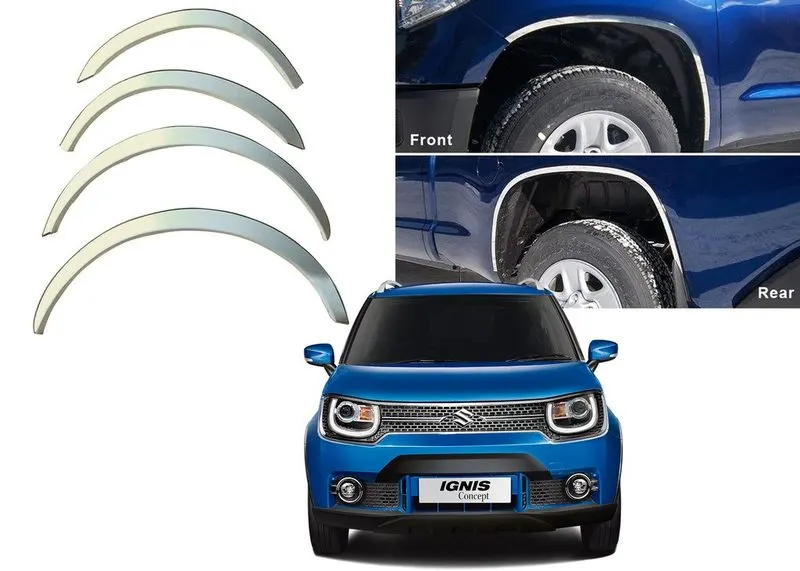
Wheel arch has 3 types of regulations such as Japanese regulations, European regulations and US regulations. This case study has been done according to European Regulations.
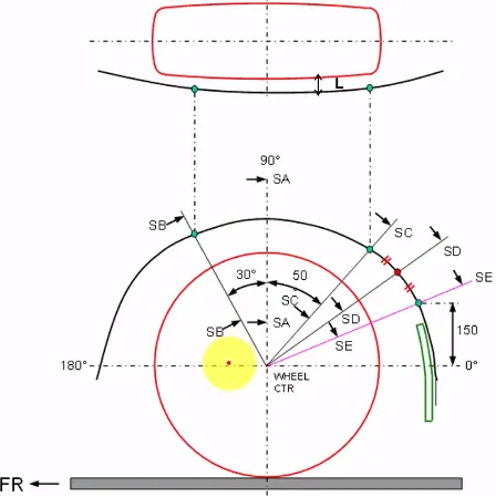
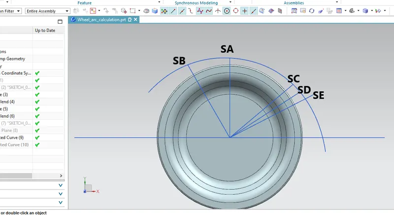
European regulations have 5 check points such as SB, SA, SC, SD, SE and the minimum clearance “L” recommended at all these 5 points on the wheel arch should be 10 mm.
If the Wheel arch model doesn’t meet the requirements as per the regulations, then the model needs to be modified accordingly. The below image shows the European regulations.
WHEEL ARCH CALCULATIONS
PROCEDURE
STEP 1: The model or the skin data provided is opened in NX CAD.
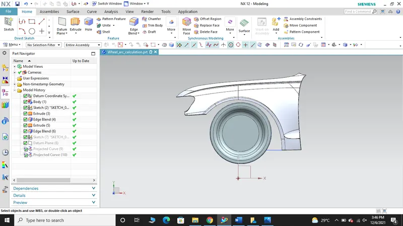
STEP 2: The center point is marked using the wheel center and a straight line is drawn accordingly.
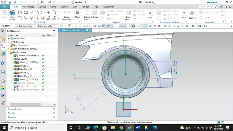
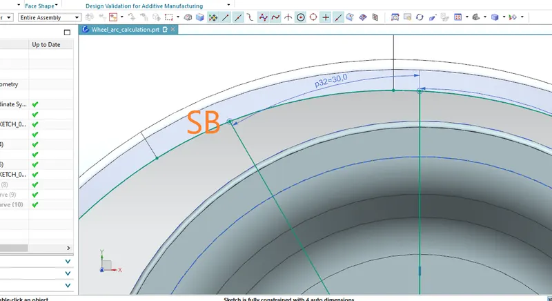
STEP 3: The line is drawn at an angle of 30 degree from the straight line and that line is SB and the straight line perpendicularly drawn to the center line is SA
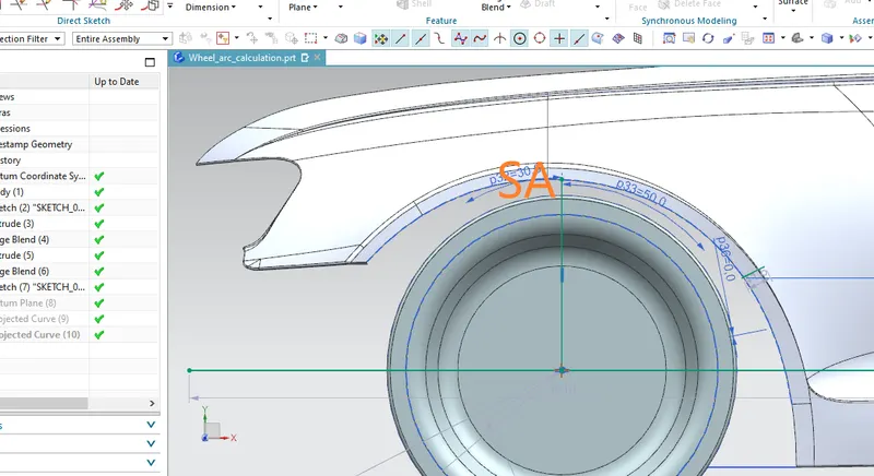
STEP 4: The line is drawn at an angle of 50 degree from the straight line to the right side of the center line and that line is marked as SC.
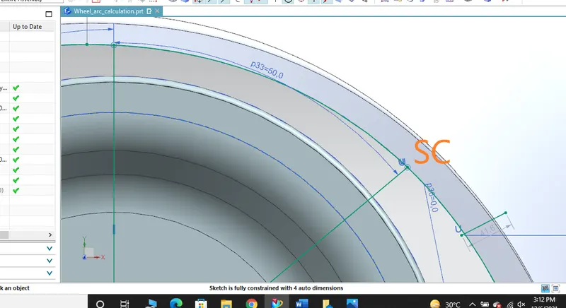
STEP 5: A line is drawn at a distance of 150 mm from the center reference line.
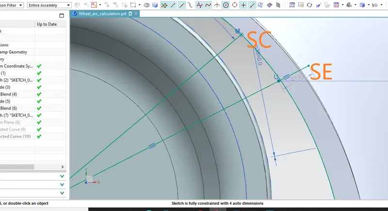
STEP 6: Another line is drawn between the line of SE and SC to get the SD
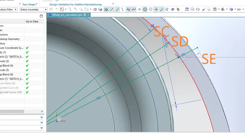
STEP 7: The datum plane is created on the outer wheel and the sketch is projected using that plane and the fender face.
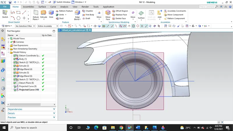
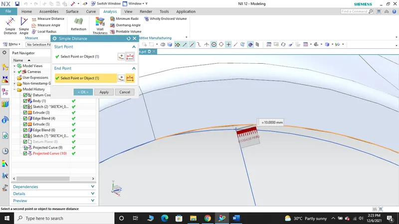
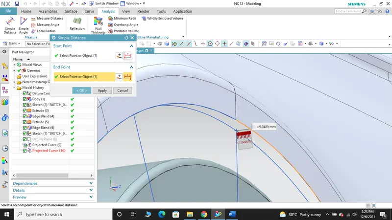
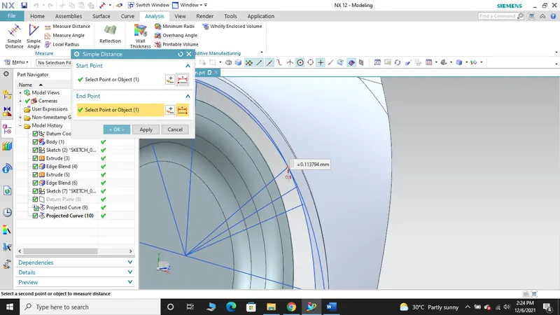
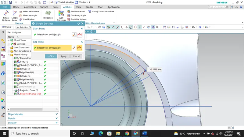
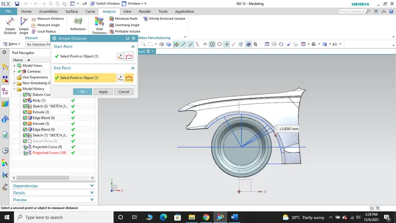
STEP 8: The points are measured accordingly and the distance checked as per the regulations in which all the points should be above 10 mm.
CLEARANCE "L" OF SB= 10 mm
CLEARANCE "L" OF SA= 9.9489
CLEARANCE "L" OF SC= 0.113794
CLEARANCE "L" OF SD = 3.0782 mm
CLEARANCE "L" OF SE = 5.8041
CONCLUSION
|
SECTION |
REQUIRED CLEARANCE (mm) |
MEASURED CLEARANCE “L” (mm) |
REMARKS |
|
SB |
10 |
10 |
PASS |
|
SA |
10 |
9.9489 |
FAIL |
|
SC |
10 |
0.113794 |
FAIL |
|
SD |
10 |
3.0782 |
FAIL |
|
SE |
10 |
5.8041 |
FAIL |
The wheel arch has been measured and calculated and the result shows except one section (i.e. SB = 10 mm) all the other section fail to achieve the minimum gap rquirement of 10mm according to the European regulations. Therefore, it is recommended to modify the model according to the regulations.