Fender Design - Wheel Arch Challenge
Aim:
To conclude the given fender and wheel design clears the European standards or not. A wheel and fender skin data are provided in .prt file to proceed further.
Introduction:
A fender is a semi-circular part which covers the side part of the engine and acts as a hub for a wheel. This protects the engine from the rain, mud, dirt and stones. This also provides safety for pedestrians. Different countries follow different design regulations. The design has to clear the standards and regulations set by the countries to be operational in those specific countries. We have two regulatory systems for wheel arch design.
- Japanese Standard:
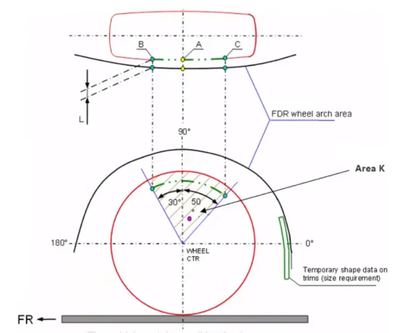
The image below shows the regulations for a wheel arch in Japan. In this challenge we are not going to check this standard.
- European standard:
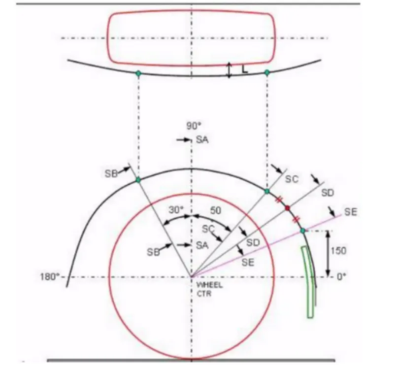
For European standard, certain points are created as shown below. The points are further measured, which is supposed to have more than 10 mm clearance. There are two values to consider, one is ‘L’ value another one is ‘a’. L is clearance from wheel to wheel arch from top view. a is clearance from wheel outside edge to wheel arch from side view.
Steps to be followed to check European standard:
- Open Wheel arch .prt file in Siemens NX.
- Create a new sketch as shown in the figure on the datum coordinate system. To create the sketch, draw two lines, one parallel and another one perpendicular (SA) to the datum coordinate system. Draw a line with 30 degrees angle, name it as SB and drawn another line with 50 degrees, name it as SC angle as shown in the figure. Draw a line (SE) on to the wheel arch with 150 mm distance from X axis. Draw another line which is equidistance from SC and SE on the wheel arch curve. Make the sketch fully constrained by providing necessary dimensions. Mark all the intersection points on to the wheel arch curve.
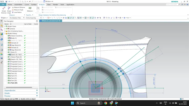
- Create a datum plane at the center of the wheel, offset to 60 mm and project the sketch created earlier.
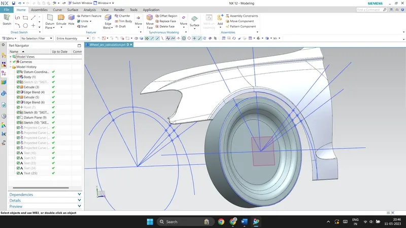
- To obtain ‘a’ value using simple measure tool measure the distance between two points created on SB line. Continue the same with the points created on SC line.
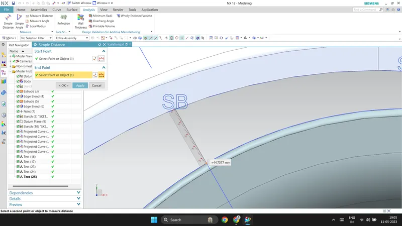
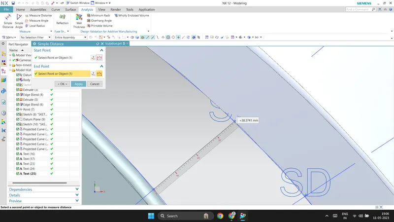
Note down the measured values.
SB = 44.757
SC = 38.374
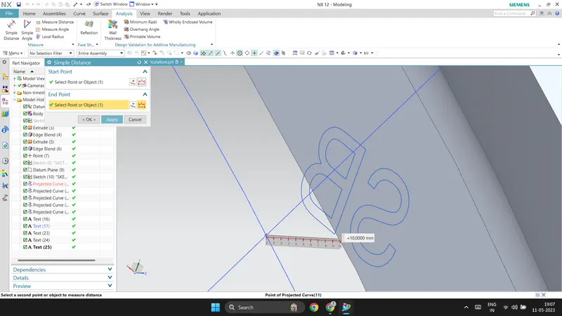
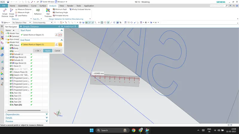
- To obtain ‘L’ value, the intersection points are further projected on the outer face of the wheel arch as shown below.
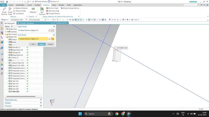
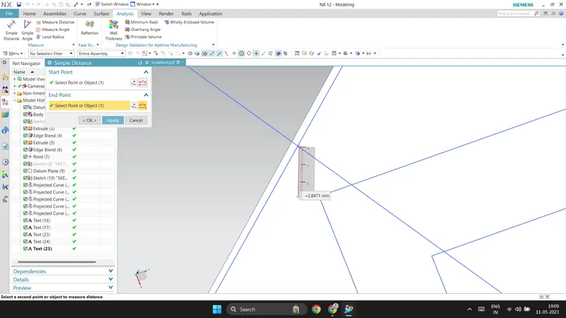
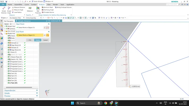
Measure the distance between all the points as shown below using simple measure tool.
Conclusion:
The results are given in the table below. L values should be greater than 5 mm, but at SC and SD it is less than 5 mm. A values are clear at every point. The given fender and wheel are not clearing European standards of wheel arch design.
|
SECTION |
L > 5 mm |
RESULT |
A > 10 mm |
RESULT |
|
SB-SB |
10 mm > 5 mm |
PASS |
44.757 mm > 10 mm |
PASS |
|
SA-SA |
9.949 mm > 5mm |
PASS |
||
|
SC-SC |
0.112 mm < 5 mm |
FAIL |
38.374 mm > 10 mm |
PASS |
|
SD-SD |
2.847 mm < 5 mm |
FAIL |
||
|
SE-SE |
5.901 mm > 5 mm |
PASS |