Fender Design - Wheel Arch Challenge
Calculate the Wheel Arch gap at required points and check whether the car passes the European standard.
Objective:
- To calculate the wheel arc clearance for given Fender model using European standards regulations.
Introduction:
- For the every vehicle have the various regulations according to their region perspective. From the regulation the Wheel arc calculation is necessary for the fender design to pass the local regulations standards.
- Wheel arch is a semi-circular area in fender, which houses the wheel well. It should have a sufficient clearance between tyre and wheel arch. So, that it doesn’t touch the wheel arch area during suspension. The clearance value differ from region to region, here are few countries regulations
Fender wheel arch regulations:
Japan Regulations
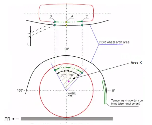
- The clearance ‘L’ for tire, hub, cap and fender is to be measured within area K and create clearance check chart to validate
- The value of L should be greater than 5mm at all positions
- Wheel guard requirement: The value of ‘a’ should be more than 5mm at line 30° forward and 50° rearwards from the central vertical axis of the wheel
European Regulations
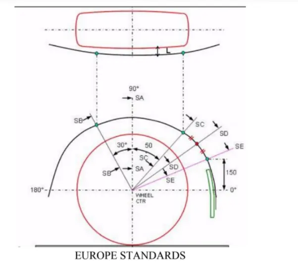
- The Clearance ‘L’ should be measured at sections SA-SA, SB-SB, SC-SC, SD-SD and SE-SE and create clearance check chart to validate
- At all the five sections the value of L should be greater than 10mm to satisfy the European Regulations
- Wheel guard requirement: The value of ‘a’ should be more than 5mm at line 30° forward and 50° rearwards from the central vertical axis of the wheel
US Regulations
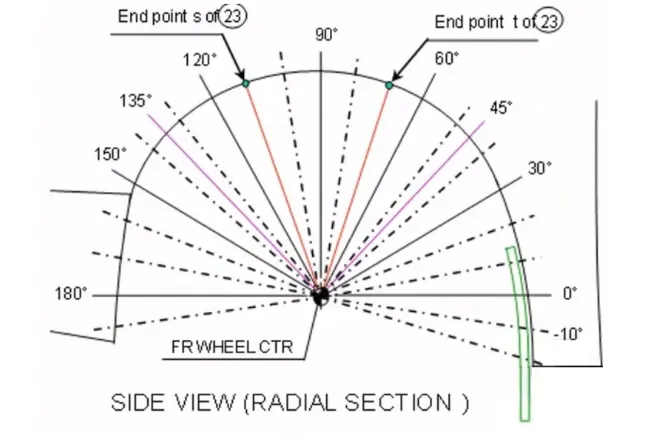
- Clearance ‘L’ is to be checked at all positions from -100° to 100° and create clearance check chart to validate
- The value of L should be greater than 5mm to satisfy the regulations
- Wheel guard requirement: The value of ‘a’ should be more than 5mm at line 30° forward and 50° rearwards from the central vertical axis of the wheel
Calculation of wheel arch area according to European Regulations
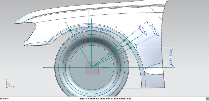
- For calculation of clearance between Wheel Arch and Wheel we have to create a sketch on the outer most face of the wheel.
- A Datum Plane is created at the outermost face of the wheel
- The sketch is created on the new Datum Plane
- A Horizontal line is drawn across the centre of the wheel
- A perpendicular line SA is dropped at the centre of the wheel
- Two lines SB and SC are created at 30° forward of SA and 50° rearward of SA respectively
- A point is created 150mm vertically above the centre line
- A line SE is drawn from the wheel centre and passes from the point created
- Another line SD is drawn from the centre of the wheel and in the middle of lines SC and SE
sketch
Actual values measured
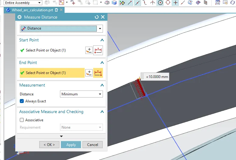
- point SB =10mm
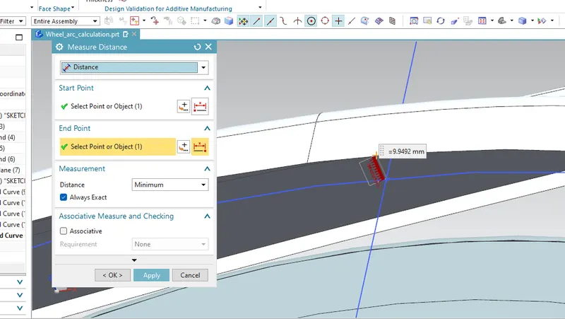
- point SA =9.9492mm
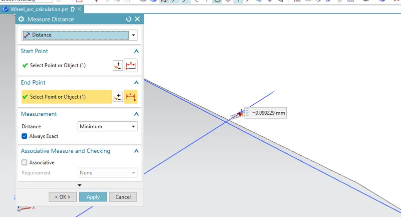
- point SC=0.099229mm
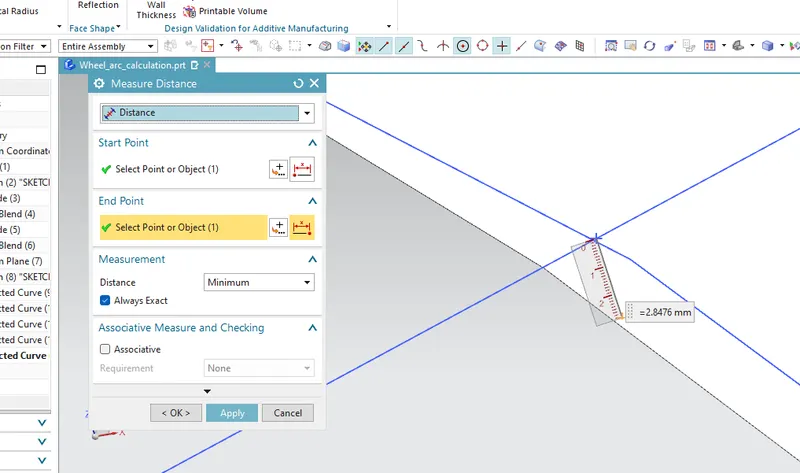
- point SD=2.8476mm
- point SE=5.92675mm
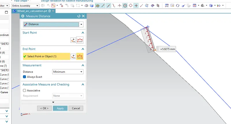
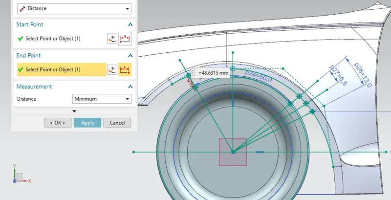
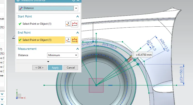
Measuring the clearance vlaue'a' for Wheel Guard Requirement
- Clearance 'a' at 30° line SB
- a=48.6315mm
- Clearance 'a' at 50° line SC
- a=43.4750mm
conclusion:
| Section | L(>10mm) | Result | a(>5mm) | Result |
| SA | 9.9492mm | Fail | ||
| SB | 10mm |
Pass |
48.6315mm | Pass |
| SC | 0.099229mm | Fail | 43.4750mm | Pass |
| SD | 2.8476mm | Fail | ||
| SE | 5.92675mm | Fail |
- The chart show only the point SB is at 10mm from the edge of the wheel.The clearance length CL of other points (SA, SC, SD, SE) is not as per European
standards. - So the fender needs to be redesigned to comply with European standards.