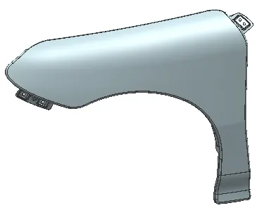
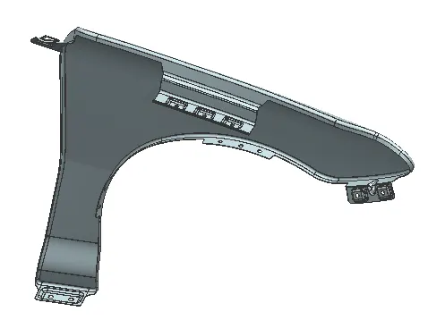
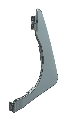
Fender Design Challenge
Aim: To design a fender considering all design requirements & with the help of skin data.
Solution:
Fender is the car body part that frames the wheel. Its purpose is to prevent sand, dirt, rocks, and other road spray from being thrown into the air by the rotating tire and close the engine component. When a vehicle is moving, tires pick up stones and hurl them in all directions. Fenders are basically present to prevent any injuries to pedestrians and contain the motion of these particles. A pair of front and rear fenders can be found on each side of a vehicle.
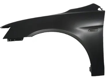
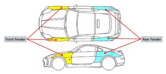
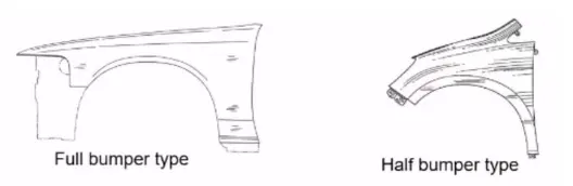
Types of Fender design over years:
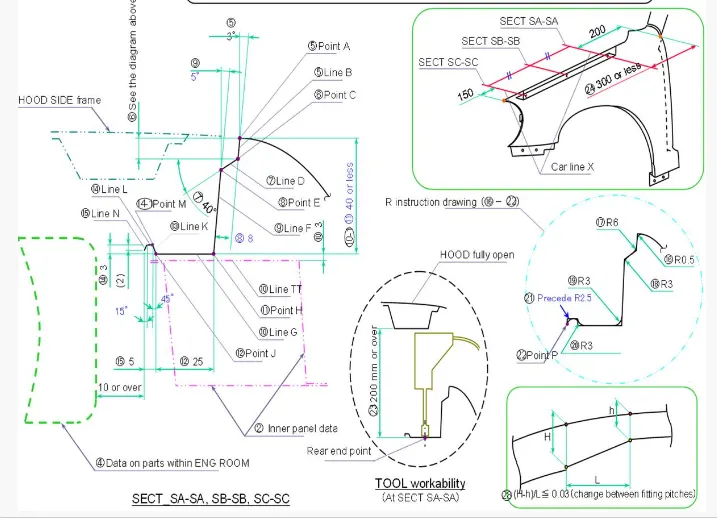
Design Features / Mounting points on Fender:
- Drip Area
- Bumper Mounting Area
- Sill Mounting Area
- Baffle Mounting Area
- A-Pillar Mounting Area
Master section Details:
Manufacturing details of fender:
- Blank size calculation would be carried out to understand material & process requirements.
- Tool & Die design as per the Skin data would be manufactured.
- Depending on the clearance of tooling & the features, single or progessive tooling/drawing will be performed.
- Our design should support & accomodate No spring back effect after drawing process.
- Piercing of mounting holes on the flat surface & check for clearance.
- Deburr sharp edges & corners for finish.
Skin Data Input:
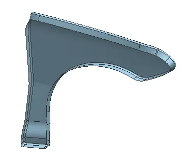
- Create Curve on surface & use Trim sheet to remove off the flanges as required from the skin data.
 '
'
Drip Area:
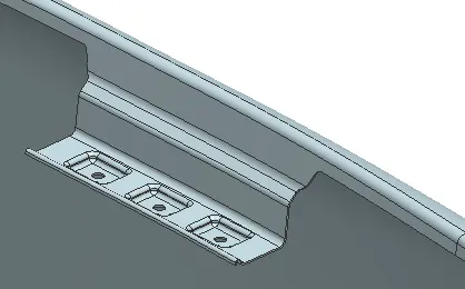
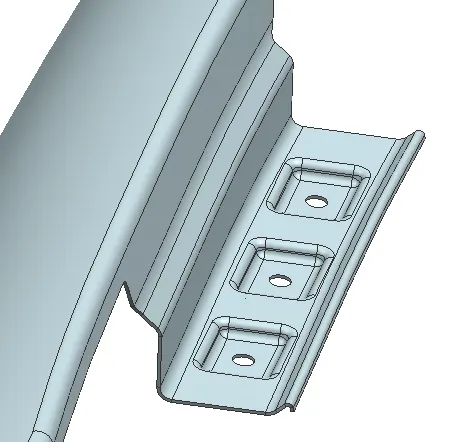
- While designing the drip area, a 150mm clearance is maintained from the front-end for headlight area and 200mm clearance from the rear for the Cowl top area.
- The depth of the drip area is maintained at less than 60mm so as to avoid the spring-back effect. Extensions are provided at the fender drip area to increase strength.
- Using law extension from the given flanges of the fender to follow the master section. Angles at which each flanges are is important for manufacturability, accessibilty & aesthetic concerns.
- Sketch the mounting area face with holes of 5 mm dia, holes should have 10mm dia flat surface for mounting.
- Create Emboss feature making sure our mounting region is on a flat surface.
- Provide blends to the surface as required.
Sill Mounting Area:
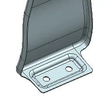
- Use Curve on surface & Trim sheet to remove the excess flange material.
- Use Extend sheet to elongate the base profile as shown below.
- Sketch the mounting profile & provide Emboss to maintain a flat mounting region.
- Sketch the holes of 5 mm dia, holes should have 10mm dia flat surface for mounting.
- Provide blends to the surface as required.
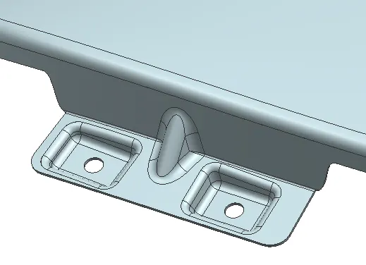
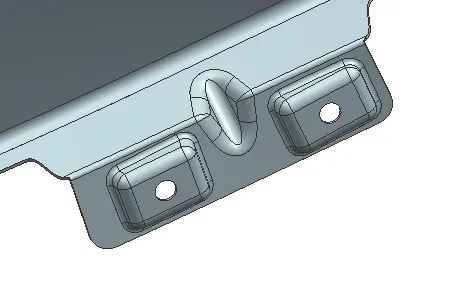
Bumper Mounting Area:
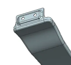
- Use Curve on surface & Trim sheet to remove the excess flange material.
- Use Extend sheet to elongate the base profile as shown below.
- Sketch the mounting profile & provide Emboss to maintain a flat mounting region.
- Sketch the holes of 5 mm dia, holes should have 10mm dia flat surface for mounting.
- Provide blends to the surface as required.
- Provide Dart/Stiffener, sheet metal strenghtening feature to provide rigidity to the mounting area.
Baffle Mounting Area:
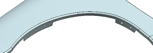
- Use Bridge Curve & Trim sheet to remove the excess flange material.
- Create a datum plane using curve & points to get a flat reference over the baffle area.
- Sketch the holes of 5 mm dia, holes should have 10mm dia flat surface for mounting.
- Repeat the same on other instances as well.
A Pillar mouting Area:
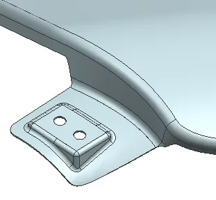
- Use Curve on surface & Trim sheet to remove the excess flange material.
- Use Extend sheet to elongate the base profile as shown below.
- Sketch the mounting profile & provide Emboss to maintain a flat mounting region.
- Sketch the holes of 5 mm dia, holes should have 10mm dia flat surface for mounting.
- Provide blends to the surface as required.
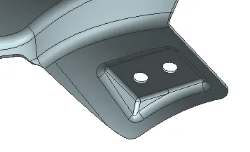
Final Fender Output: