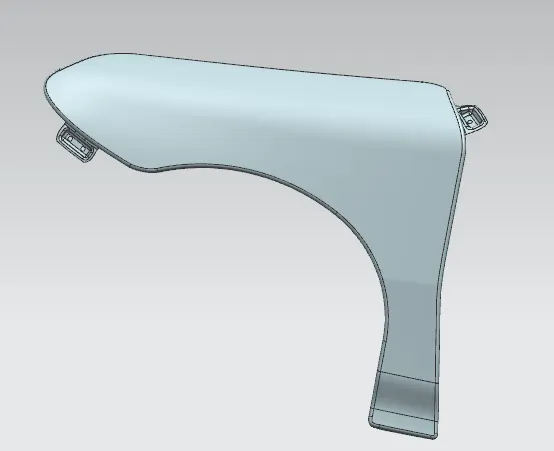
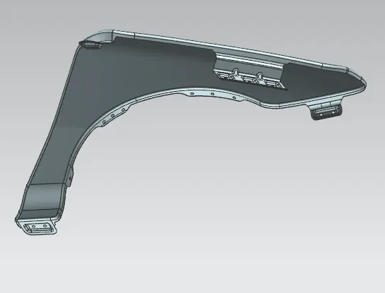
Fender Design Challenge
FENDER DESIGN
FENDER
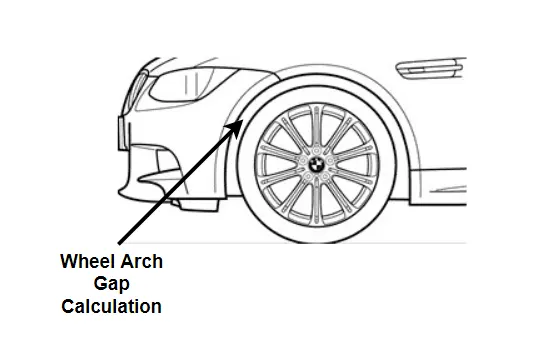
Fender is the american english term term for the part of an automobile or other vehicle body that frames a wheel well (the fender underside). Its primary purpose is to prevent sand, mud, rocks, liquids, and other road spray from being thrown into the air by the rotating tire. Fenders are typically rigid and can be damaged by contact with the road surface.
Sticky materials, such as mud, may adhere to the smooth outer tire surface, while smooth loose objects, such as stones, can become temporarily embedded in the tread grooves as the tire rolls over the ground. These materials can be ejected from the surface of the tire at high velocity as the tire imparts kinetic energy to the attached objects. For a vehicle moving forward, the top of the tire is rotating upward and forward, and can throw objects into the air at other vehicles or pedestrians in front of the vehicle
The fender's openings for the wheel wells tend to be much larger than the diameter of the tire, because they do not move with the tire suspension and consequently must be large enough to allow the full range of tire motion on the suspension without touching the interior of the wheel well.
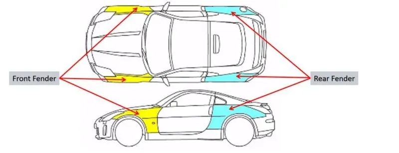
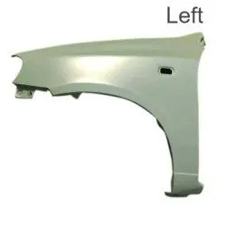
Wheel Arch is the semi-circular part of the fender positioned above the wheel of the vehicle. The design of the wheel arch of the fender should be such that it must shield wheels and protect both passengers compartment and pedestrians from the projection of water, mud and stones.The wheel arch area of the fender is usually designed as a cover or shield over the tyre along its perimeter to stop any debris or stones,dirt,sand,snow,etc, from getting thrown into the vehicle or the BIW area as well as outside the vehicle and on to other vehicles or pedestrians on the road.For the vehicle to has its permit in different countries, the wheel arch of fenders must be compliant with the standards and regulations set by respective countries.
TYPES OF FENDER
1. FULL BUMPER TYPE:
The full bumper type fender was used in old cars, it covers the full area until the front lighting. But it has a lot of sheet metal material which is unnecessary and increases the weight of the fender. This type of fenders are no longer used in automobiles.The problem associated with this kind of fender is there is a lot of wastage in the blank and every inch of a material is a cost to the industRY
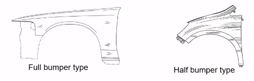
HALF BUMPER TYPE:
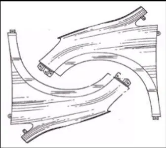
These fenders are mainly used for serving the purpose of cost-cutting and reducing enough proportions of the steel wait resulting in a reduction of the weight of the vehicle slightly. They can be economically manufactured, i.e by slightly increasing the blank size, we can produce two fenders at a time.
Manufacturing Process:
One of the most important things about metal is that it can undergo plastic deformation. That doesn't mean metal is made out of plastic, but it can do one of the things that plastics can: It literally can take on almost any shape that we can imagine.
Blanking:
The process of deformation begins with a blank, a quantity of metal in some basic form that will undergo the change in shape. The blank becomes the workpiece -- the piece of metal to be reshaped -- in the metal forming process. For automotive metal forming, the blank is often made of sheet metal, which can be stamped, cut or bent into a shape needed for an automobile's body. Alternatively, it can be a solid block of metal in a cubical or lens-like shape.
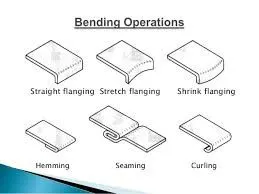
Bending:
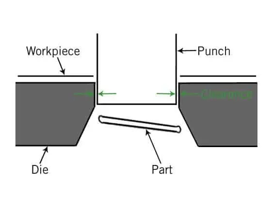
In bending, force is applied to a sheet metal workpiece to produce a curvature of the surface. Bending is generally used to produce simple curved surfaces rather than complex ones. A mechanically operated press drives a punch against sheet metal, forcing it into a simple die with enough pressure to produce a permanent change in the metal's shape. The amount of pressure is important. If not enough pressure is applied, the metal can simply spring back into its original shape. If too much is applied, it can break.
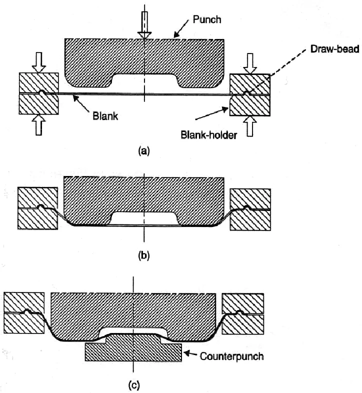
Drawing: In drawing, the sheet metal is forced against a die that has been cut into the three-dimensional, often curved shape that the sheet metal is to take on. In effect, the die is used as a mold for the metal. This technique can produce relatively complex shapes. Once again, pressure is applied to the workpiece using a hydraulically or mechanically operated punch. There are a number of dangers involved, not so much to people (since the process is largely mechanized) but to the metal itself. It can crack from too much pressure or wrinkle from its interaction with the die. Lubricant can be used to make the metal slide more smoothly against the die, avoiding the possibility of wrinkling. Alternatively, the wrinkled edges can be trimmed from the metal in a separate operation. This method is commonly used to make auto body parts and fuel tanks.
Stamping: In stamping, a device called a stamping press is used with a series of dies to cut and form metal into various shapes. This is commonly used to make auto parts such as hubcaps and fenders.
Extrusion: Extrusion can be used to produce long metal objects, such as rods and tubes. The metal workpiece is forced into a die with a hole in the opposite end. The metal is extruded through the hole to form the shape. Extrusion can be used to manufacture important parts of a car's drive train or the anchors that hold seatbelts in place.
Embossing:
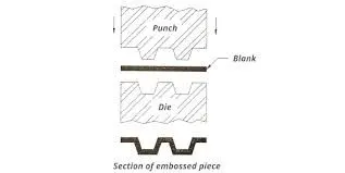
Embossing is a metal forming process for producing raised or sunken designs or relief in sheet material by means of matched male and female roller dies, theoretically with no change in metal thickness, or by passing sheet or a strip of metal between rolls of the desired pattern.
Metal sheet is drawn through the male and female roller dies producing a pattern or design on the metal sheet. Depending on the roller dies used, different patterns can be produced on the metal sheet.
Characteristics of the metal embossing process include:
- Its ability to form ductile metals,
- Its use in medium to high production runs,
- The ability to maintain the same metal thickness before and after embossing,
- The ability to produce unlimited patterns, depending on the roll dies, and
- The ability to reproduce product with no variation.
Springback
springback is the geometric change made to a part at the end of the forming process when the part has been released from the forces of the forming tool. Upon completion of sheet metal forming, deep-drawn and stretch-drawn parts spring back and thereby affect the dimensional accuracy of a finished part. The final form of a part is changed by springback, which makes it difficult to produce the part. During the development of tools, springback is compensated by software in order to remove the part from the tool straight away in the required dimensions
OBJECTIVE
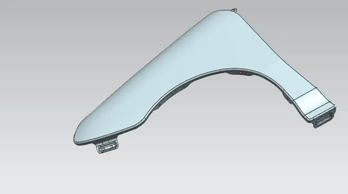
Design a front fender from the given skin data and the master section provided with Drip mounting, A-pillar, Sill, Bumper and Baffle (splash) Mounts
DESIGN CONSIDERATIONS
The front fender has basically five mounting positions with respect to the other components. The mounting positions are as follows:
- Drip Area Mounting.
- A-Pillar Mounting.
- Sill Mounting.
- Bumper Mounting.
- Baffle Mounting.
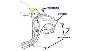
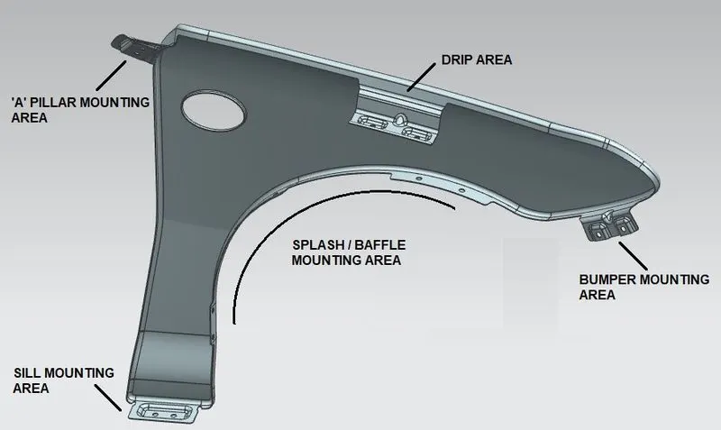
For the creation of the Drip Area Mounting, the given Master Section is followed, and the other mounting points are created by assuming appropriate positions with the respected components.
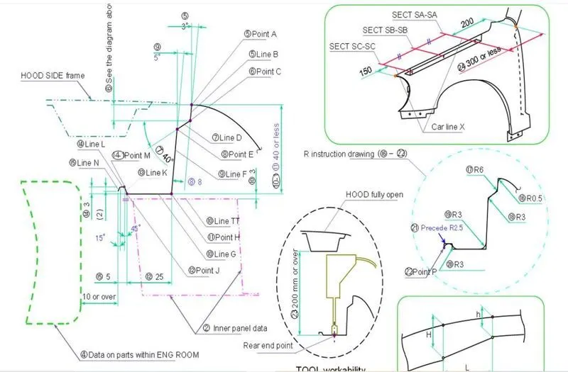
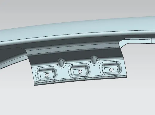
DRIP AREA MOUNTING
Drip area mounting is an important part of the fender. this mounting is attached to the engine compartment of the car. fender drip area is mounted via weld nuts to the engine compartment. A min of 150mm distance is kept from the front side and a distance of 300mm or less can be kept on the rear side. the total length of drip area from the top of the fender should be less than 40mm, this is to avoid the spring back during the manufacturing. the edge of the mounting should be at least 10mm away from any nearby component in the engine. A rigidity bead is provided at the end to increase the strength of the mounting.
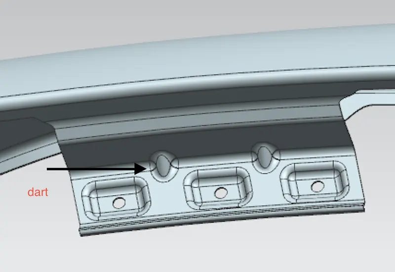
dart
A narrow ridge of metal used to strengthen a flange of a part. The dart is formed into the edge of the flange and the part.
A PILLER MOUNTING
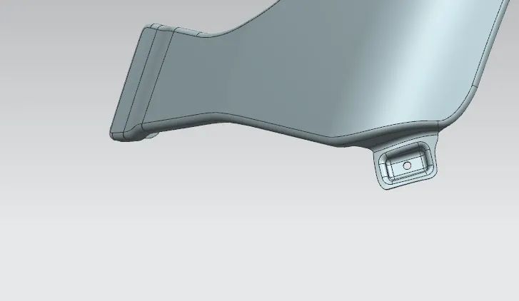
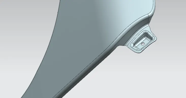
In the case of cars, “pillars” refer to roof pillars, and they're lettered front to back. A-Pillars straddle the windshield.The A-pillar area mounting depends upon position of the A-pillar of the car. the emboss and hole for fastening the fender is provided in the panel.
SILL MOUNTING
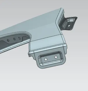
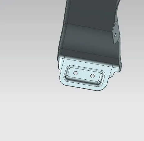
Sill is the panel that is part of a car body at the bottom of the doors .The sills are a vital structural part of a unibody chassis, they provide strength and rigidity which is important in the event of an accident . the bottom end of fender is mounted on the sill body.
BUMPER MOUNTING
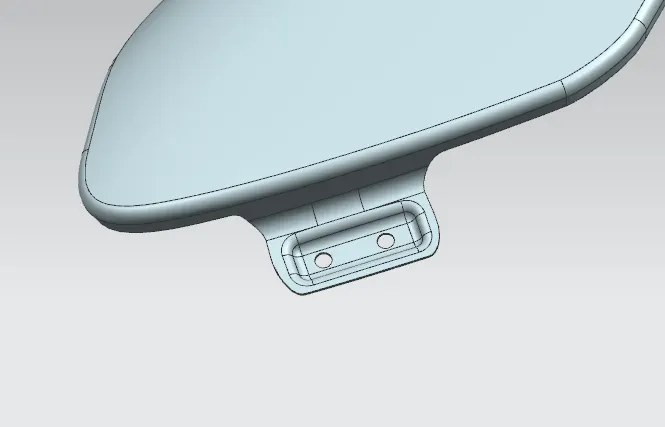
Bumper mounting area is used to fix the plastic bumper to the fender with the help of the fasteners
BAFFLE MOUNTING
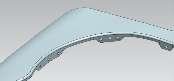
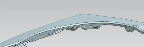
Baffle mounting are clip fit type of mounting on the inner wheel arch side of the fender . Baffle protects the car engine compartment and pedestrains from causing injuries from chip out debris on the road when the car is in motion. Baffle mounting are holes are provided to support the baffle. it is a Plastic which is used as a barrier between fender & outside particles, dust, rocks. Plastic cover is used to protect the dust & rock and it is mounted on Fender via Trim clips.
CONCLUSION
A front fender with Drip mounting , A-pillar mounting , Sill mounting, Bumper mounting and Baffle (splash) Mounts is designed from the given skin data and the master section