Fender Design Challenge
DESIGNING OF FRONT FENDER USING SIEMEN NX
OBJECTIVE
The main objective is to learn the Basics of the BIW (Body in white) through designing the Front Fender" of a car by considering all the Protocols and Standards of BIW Design.
INTRODUCTION
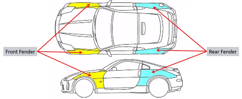
Fender is the US English term for the part of an automobile (vehicle body) that frames a wheel well (the fender underside).
Its primary purpose is to prevent sand, mud, rocks, liquids, and other roads spray from being thrown into the air by the rotating tire.
When a vehicle is moving, tires pick up stones and others and hurl them in all directions. Fenders are basically present to prevent any injuries to pedestrians and contain the motion of these particles
Most passenger automobiles have four fenders, one over each wheel. For vehicles with a narrow car body that exposes the tire, the fender is an exposed curve over the top of the tire. For wide body vehicles that cover the tire, the fender forms the wheel well surrounding the tire and is not directly visible from above the car body. Wheel wells tend to be much larger than the diameter of the tire because they do not move with the tire suspension and consequently must be large enough to allow the full range of tire motion on the suspension without touching the interior of the wheel well.
More elaborate designs include fender skirts for enclosing the outside edge of the wheel well and stylized pontoon fenders for exposed fenders.
EVOLUTION OF FENDER DESIGN
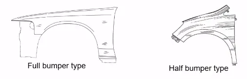
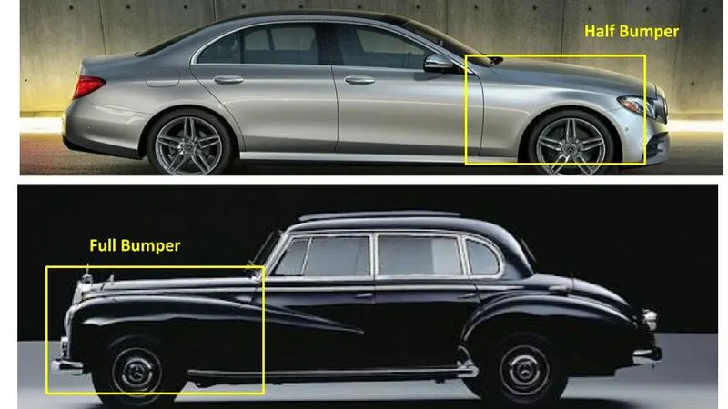
In the '90s mostly full bumper type fenders were used but due to cost and weight consideration, they had significant modifications in design and now is considered as half bumper type fenders. Half bumper type fender helps in cost-cutting as well as weight reduction thus increases productivity and performance.
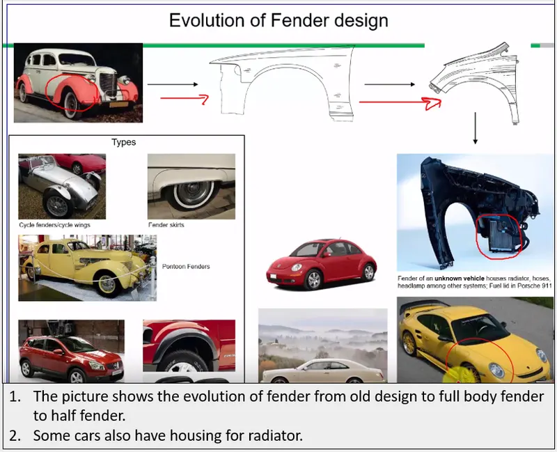
There are two types of fenders :
- Full bumper type
- Half bumper type
Mounting
There are 5 mounting points in a Fender They are
- Body
- A-pillar
- Sill
- Cowl
- Drip
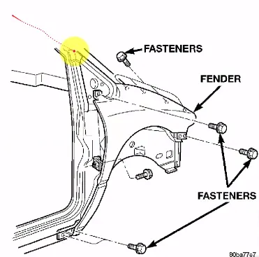
Designing of the mountings
In this project, we are mainly dealing with the designing of the four mountings of a fender which are the Drip area. A pillar mounting, Sill mounting and the Bumper mounting.
There are some considerations we must take care of while designing.
The holed surfaces where the fasteners should use must be flat.
A 5 mm flat surface should be maintained around the holes for the fasteners.
Darts and Beads must be used in proper bends in order to maintain the strength of the mountings. Among these mountings, the most critical mount is the Drip area, where there are some extra factors to consider. For creating the drip mount the location of the A-pillar mount must be known.
So first we need to create the A-pillar mounting.
A-pillar mounting
There are three pillars a car body has generally, which are A, B&C. A pillar is on the front side which holds the windscreen on either side. B pillars are located at mid of the body: doors of the back passenger compartment are mounted on it. C pillars are located on the rear side of the body where it supports the rear door and window A-pillar mount will be fastened A-pillar.
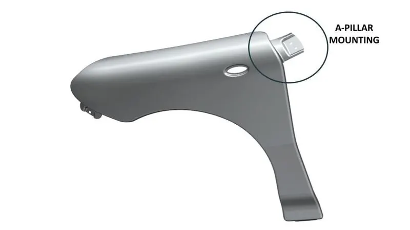
A-pillar mounting is the area where the fender attaches the A-pillar using fasteners. Here I have created a flange of approximately 50 mm in length and I have created embosses having a plane as an end cap for achieving the flat surface for the fasteners. I have also maintained a 5 mm flat surface around the holes.
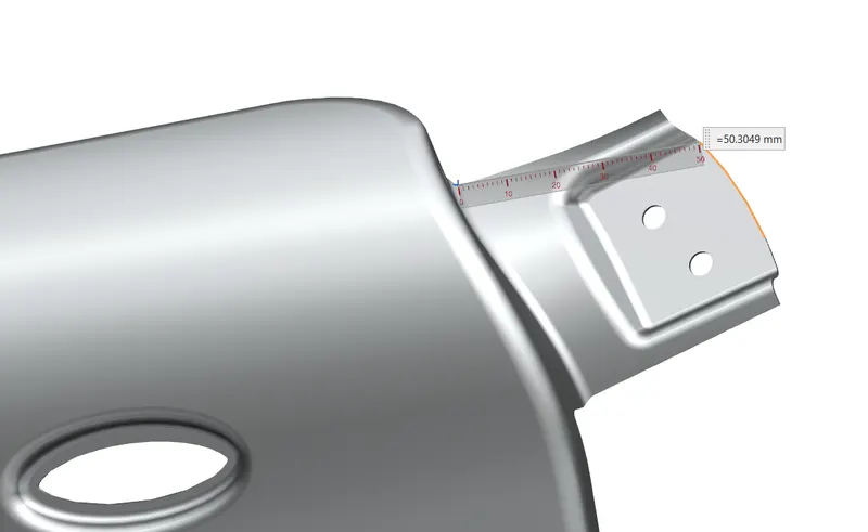
Methodology:
- First, we trim off unnecessary sheet to get proper section for mount creation by using curve on surface and trim sheet command.
- Now we left with curved surface of fender, if we extend the curved section using law extension then it will create lots of complexity while creating fastener mounting so for ease we not move with law extension but we create intersection by creating a line on curved surface and then extend it horizontally on both side of line and further we use extend and trim command to get perfect intersection of curved surface and line surface.
- Apply bend using edge bend command of 3mm.
- Create a datum plane using horizontal surface and sketch profile a rectangular profile on it use it for emboss. Also apply 5mm blends to it.
- Trim sheet at emboss section using circular curves for fasteners.
Drip area designing
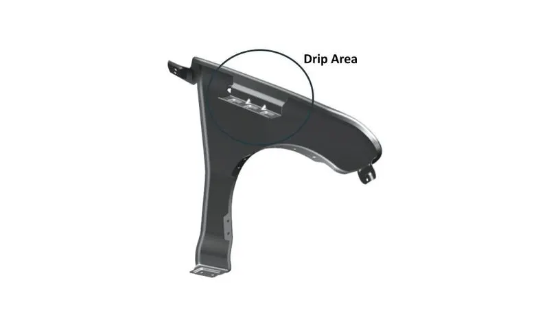
The drip area is the mounting of the fender which mounts the fender to the engine compartment. The drip area is usually in between the headlight housing and the cowl top. As it is in between those two components (headlight, cowl top) there are some factors to consider while designing the drip area. Here I am taking a master sketch of a fender as another reference and according to that, I am going to create the model.
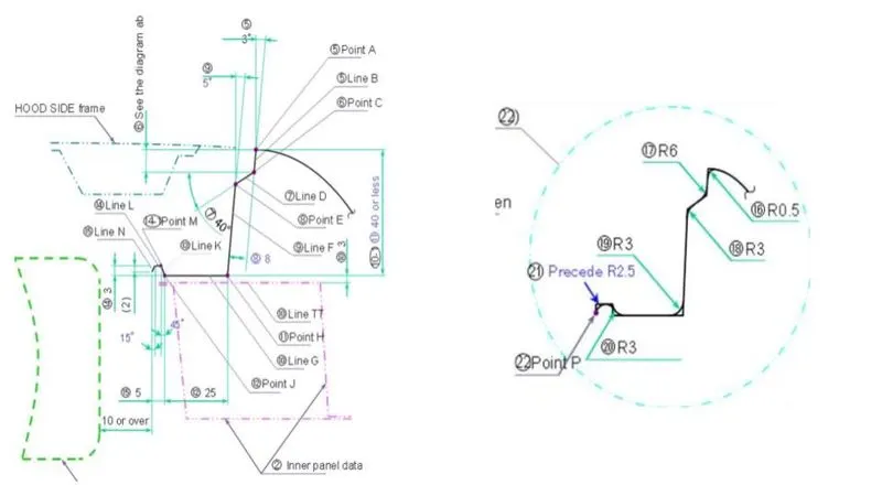
From the master section, we found that
1. Form bumper side position of drip area lies at 150mm apart, this space will be used for a head lamp.
2. From the back side there will be a maximum of 200 mm clearance for cowl mounting.
3. There must be a 10mm clearance between the engine room and drip munt.
4. Height of the drip varies up to 40mm so it is feasible to manufacture and there will be no shaking and less spring back.
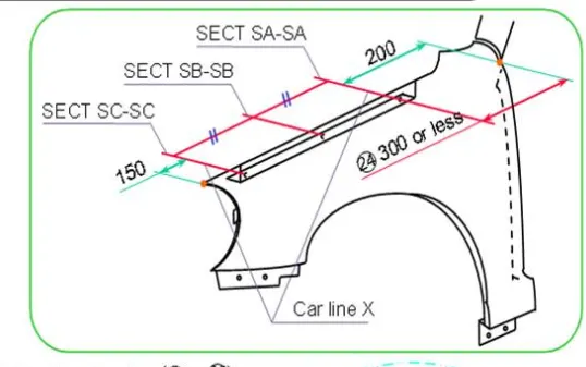
The overall length of the drip must be 40 mm or less. More than 40 mm will cause to spring back effect at the drip area resulting in NVH.(noise, vibration, and harshness) Tool workability: A minimum length of 200 mm must be maintained in between the bottom flange of the drip and the hood of the car when it is in opened condition to ensure the easy use of tool inside the hood when adding fasteners.
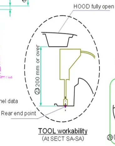
A 10 mm or more distance must be maintained from the engine room to the end of the Drip area.
The surface for the fasteners must be flat
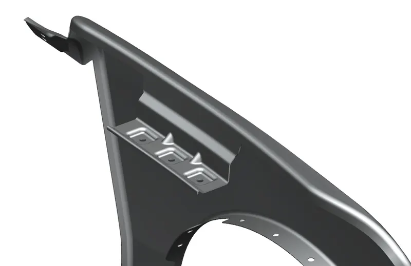
Methodology:
- Import skin data received from the styling team.
- Identify A-pillar mount area for references and draw curves on the surface to trim off extra surfaces.
- Create a datum plane from the front side or bumper side at 150mm.
- Create a datum from A-pillar which is up to 200mm a part and trim unnecessary sections.
- Now use law extend to extend sheet between last two planes and create complete drip profile as per master section.
- Create dart to impart strength and stiffness to long drip profile.
Sill mounting
Sill mount connects at bottom of car body frame. It is generally at bottom of the front doors and unites with the floor.
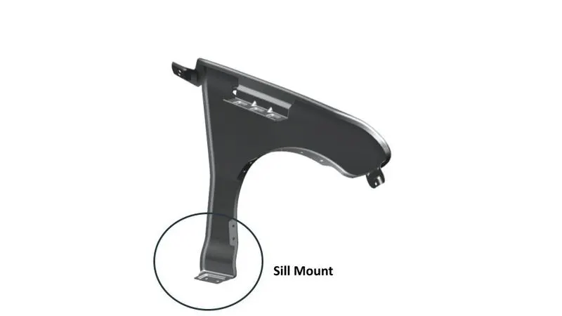
Sill mounting is Another mounting in the fender which attaches the sill to the fender using the fasteners. Same as the A-pillar mounting I have created a flange and made 2 embosses with flat surfaces and also 5 mm flat surface around the hole is maintained
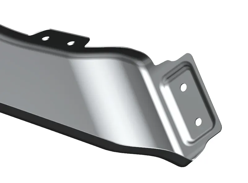
Methodology:
- Trim of unnecessary surface to get proper surface for mount creation using a curve on the surface and trim sheet commands
- Use law extends to extend surface up to 25mm vertical or collinear with the previous surface.
- Create a datum plane using an extended surface which is parallel to it.
- Sketch a rectangular profile on the datum plane and create emboss using it to offset 5mm from the datum plane. Apply edge blend of 3mm to get smooth corner surface and trim off two circular curves from the sheet using trim sheet curve.
Bumper mounting
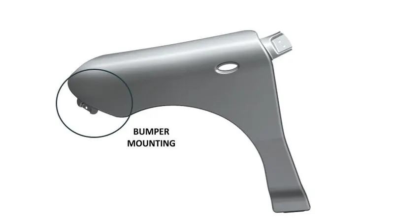
A structure attached to or integrated on the front and rear side to absorb impact in collision thereby reducing maintenance cost. This is designed in such a way that they mitigate injury to pedestrian legs through the use of soft materials like foam, crushable plastics, etc. The fender will be attached to the bumper through bumper mountings.
The part which attaches the bumper to the fender Consideration for bumper mounding is the same as the sill and A-pillar mounting.
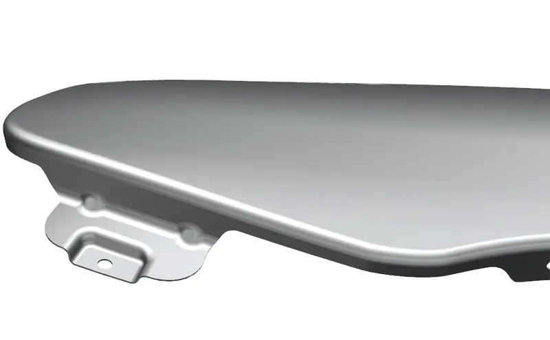
Methodology:
- Trim unnecessary portion if it is there through trim sheet command.
- Extend sheet horizontally using law extension for mount creation.
- Create rib-like structure using dart command to give strength to it. . Apply blends to the corner of 5mm.
- Create a Datum plane using a surface and sketch two rectangular profiles and two circles on it.
- Create emboss using sketched profile up to 5mm. Apply blends to it. Trim off circular section for fatteners using Trim sheet.
Baffles Mount
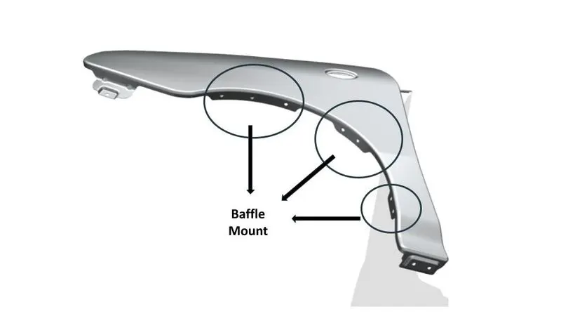
A splash protector mounting is introduced on top of the wheel to restrict debris into the engine compartment, to mount this protector baffle mounts are used having holes in it.
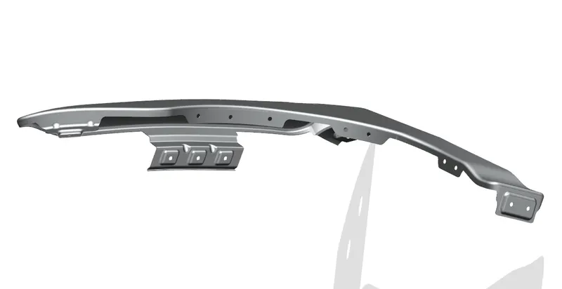
Methodology:
- Use previous sheet body for baffle creation raw splines using curve on surface command on the circular periphery and trim off unnecessary section to get three faces for mount creation.
- Create a datum plane using three-point of a particular section or use surface directly, plane will be parallel to surface. Using daturn plane create sketch on surface and draw circles for hole creation, now exit sketch.
- Use trim sheet command to trim the circular curves through sheet body.
- Do same process for two more surfaces respectively.
- Avoid any sharp corners.
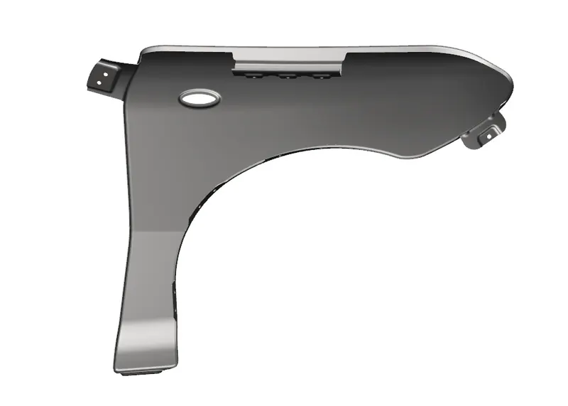
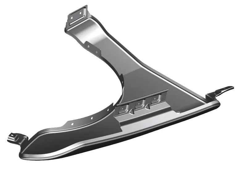
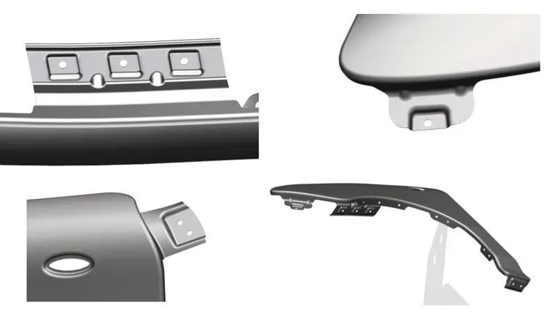
Few images of the final design
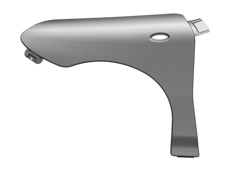
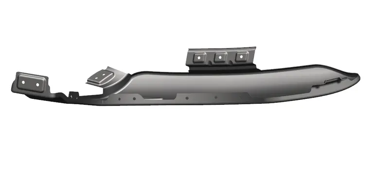
CONCLUSION
The Fender and its all mountings have been successfully Created by considering all the standards and parameters of BIW-fender design