Fender Design Challenge
AIM
To design the fender by following the input skin data and master sketch by using nx cad
SOFTWARE USED
Nx cad
FENDER
Fender is the American English term for the part of an automobile, motorcycle or other vehicle body that frames a wheel well (the fender underside).
Its primary purpose is to prevent sand, mud, rocks, liquids, and other road spray from being thrown into the air by the rotating tire. Fenders are typically rigid and can be damaged by contact with the road surface. Sticky materials, such as mud, may adhere to the smooth outer tire surface, while smooth loose objects, such as stones, can become temporarily embedded in the tread grooves as the tire rolls over the ground. These materials can be ejected from the surface of the tire at high velocity as the tire imparts kinetic energy to the attached objects. For a vehicle moving forward, the top of the tire is rotating upward and forward, and can throw objects into the air at other vehicles or pedestrians in front of the vehicle.
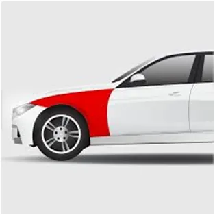
TYPES OF FENDER
FULL FENDER
Full fender type is traditional type of fender where more material consumption is observed. This type is used in old design of automobiles where it increases the overall weight and thus reduces performance. The maintenance also relatively more due to more surface.
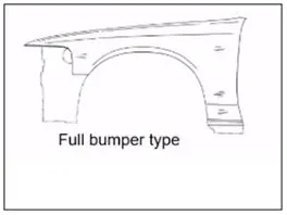
HALF FENDER
Half fender type is modern design where less material consumption is observed, so productivity increases by reducing size of blank and thus providing more performance. The maintenance also relatively low compared to full bumper type.
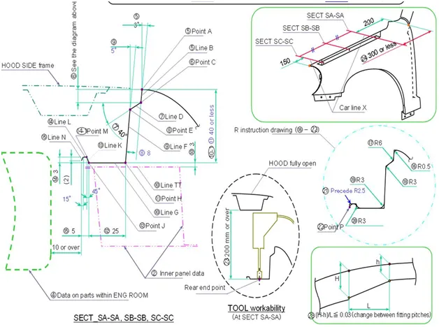
MASTER SKETCH
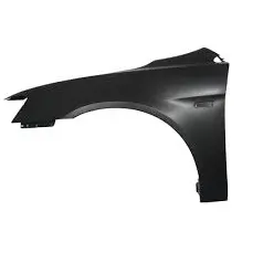
INPUT SKIN
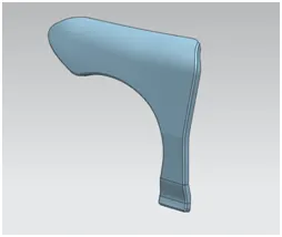
To fix the fender into other parts,mountings have to design in fenders by following the master sketch.the mountings are
- Drip mounting area
- Bumper mounting area
- Baffle mounting area
- Sill mounting area
- A mounting area
DRIP MOUNTING AREA
- Offset the edge boundary to 5mm and extrude the surface
- This mounting is fitted into engine compartment
- A 150mm from side and a distance 300mm or less from rear side
- A 10mm or over from engine, have to maintain the height of 40mm of drip.
- Drat have been created for increasing the stiffness of mountings.
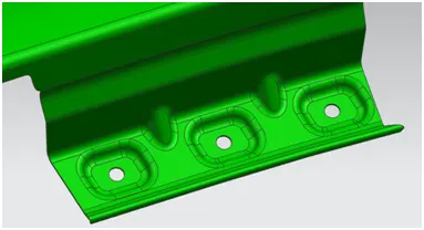
Bumper mounting area:
- Offset the edge boundary to 5mm and extrude the surface
- This mounting is fitting into bumper.
- A 25mm flange is created for the mountings.
- M6 hole is drilled for fasteners
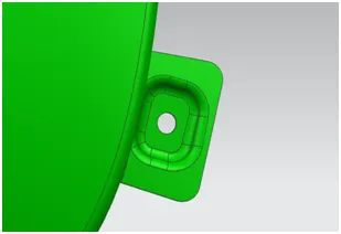
Baffle mounting area:
- Offset the edge boundary to 5mm and extrude the surface
- This mounting is used to fit at wheel arch for baffle
- Baffle is plastic unit used to fit for splash mounting
- creating the holes for fasteners
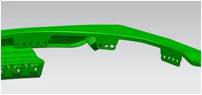
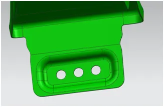
Sill mounting area:
- Offset the edge boundary to 5mm and extrude the surface
- This mounting is used to fit at sill
- Emboss is created and the edges are blended
- M6 hole is drilled for fasteners
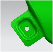
A mounting area:
- Offset the edge boundary to 5mm and extrude the surface
- A pillar mounting is a vertical support on a vehicle. it holds the windshield set up
- Emboss is created and the edges are blended
- M6 hole is drilled for fastener
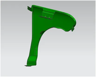
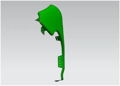
FENDER VIEWS
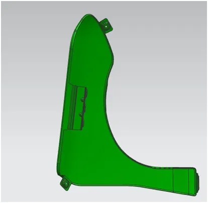
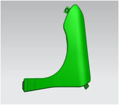
CONCLUSION
Thus the fender design has created using nx cad