Fender Design
AIM
To design the fender according to the given sketch, design parameters related to the industry standards.
OBJECTIVE
The main objective of this project is to learn the basic tools, commands and surface modelling of the fender design using Siemens NX CAD, To design a fender mounting on the given model by using master sketch by considering the safety and manufacturing feasibility for possible mounting region.
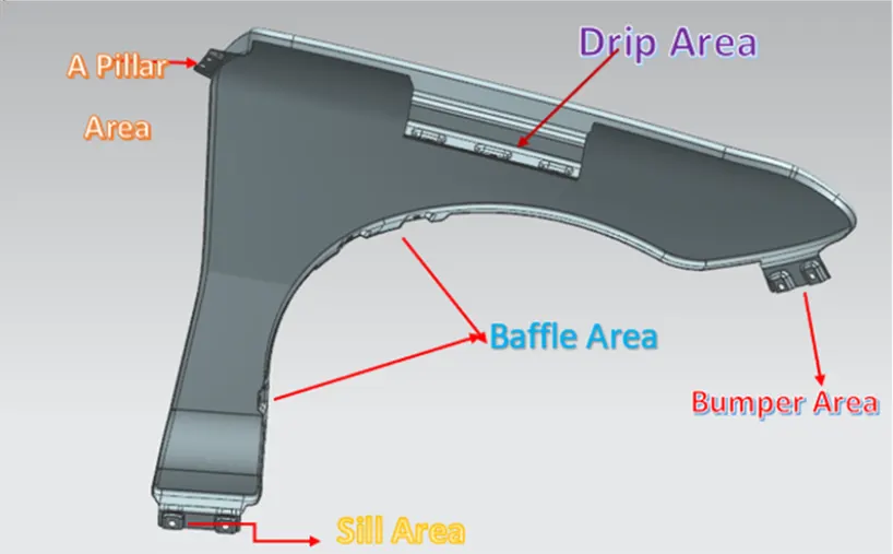
1) Design Drip area
2) Design sill mount area
3) Design baffle mount area
4) Design A pillar mounting area
5) Design Bumper mounting area
INTRODUCTION
A fender is a piece of vehicle, cycle or some other vehicles, its fundamental job is to prevent sand, mud, rocks, liquids, and other road sprinkles from being thrown into the air by the turning tyre. In extra to fender various part like internal mount, side and cowl mount that are joined with the helps of nuts. They give the satisfactory protection to the engine room portions and suspension area etc.
Fender is the American english articulation for the piece of a vehicles, cruiser or other vehicle body that trace a wheel well.
USE OF FENDER
- Ensure the safety to the other vehicle and pedestrian from rough material being thrown by the rotating wheels.
- Fender helps to improve the airflow around the vehicle, reduce the drag and improving the fuel efficiency.
- In minor collision or impacts, fender absorb the some of the forces, reducing the damages to the main body of the vehicle.
- they contribute the vehicles overall design, giving it a sleek and finished look.
TYPE OF FENDER
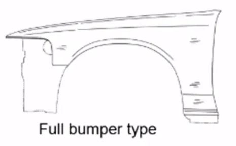
Full fender type: The full fender type is the standard sort of fender where more material use is observed. This sort is utilized in the old designs of vehicles where it is manufactures the general weight and suitably lessen execution.
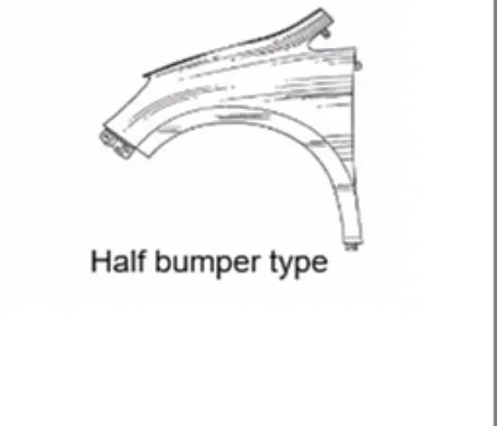
Half fender type: Half fender types are mainly used for serving the purpose of cost-cutting and reducing enough proportions of the steel weight resulting in a reduction of the weight of the vehicle slightly. They can economically manufactured.
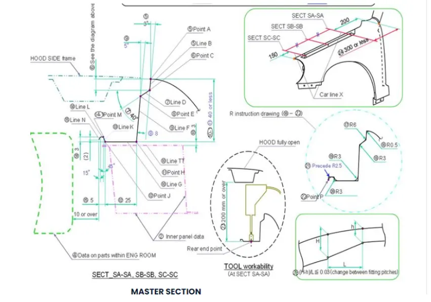
MASTER SECTION
DESIGNING
Design of Drip mounting area:
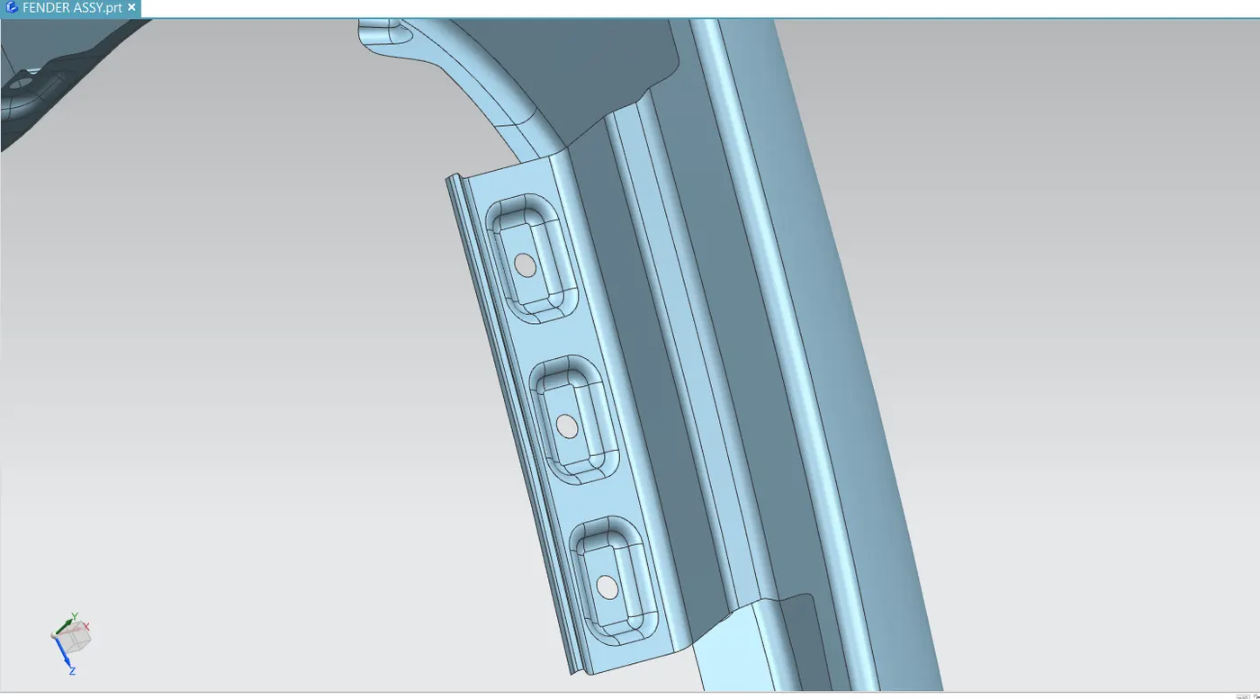
- It is the most important mounting unit of the fender. This portion is connected in engine compartment, hence there are lots of design constraint are to be followed while designing the fender.
- While designing the drip area we have to leave initially leave 200-300 mm for cowl top.
- For placing the headlamp we have to leave at least 150 mm at the front while designing the fender
- Cowl top part consists pf wiper motor and its attachments
- Embossing are provided on the mounting to strengthen them during fastening.
DESIGN OF SILL MOUNTING AREA
Sill is the panel directly below the bottom of the door supporting part. The bottom of the fender is mounted on the sill body for reinforcement of fender panel, thus the sill mounting position is designed with emboss. M5 fasteners are used to fix the fender with the sill part.
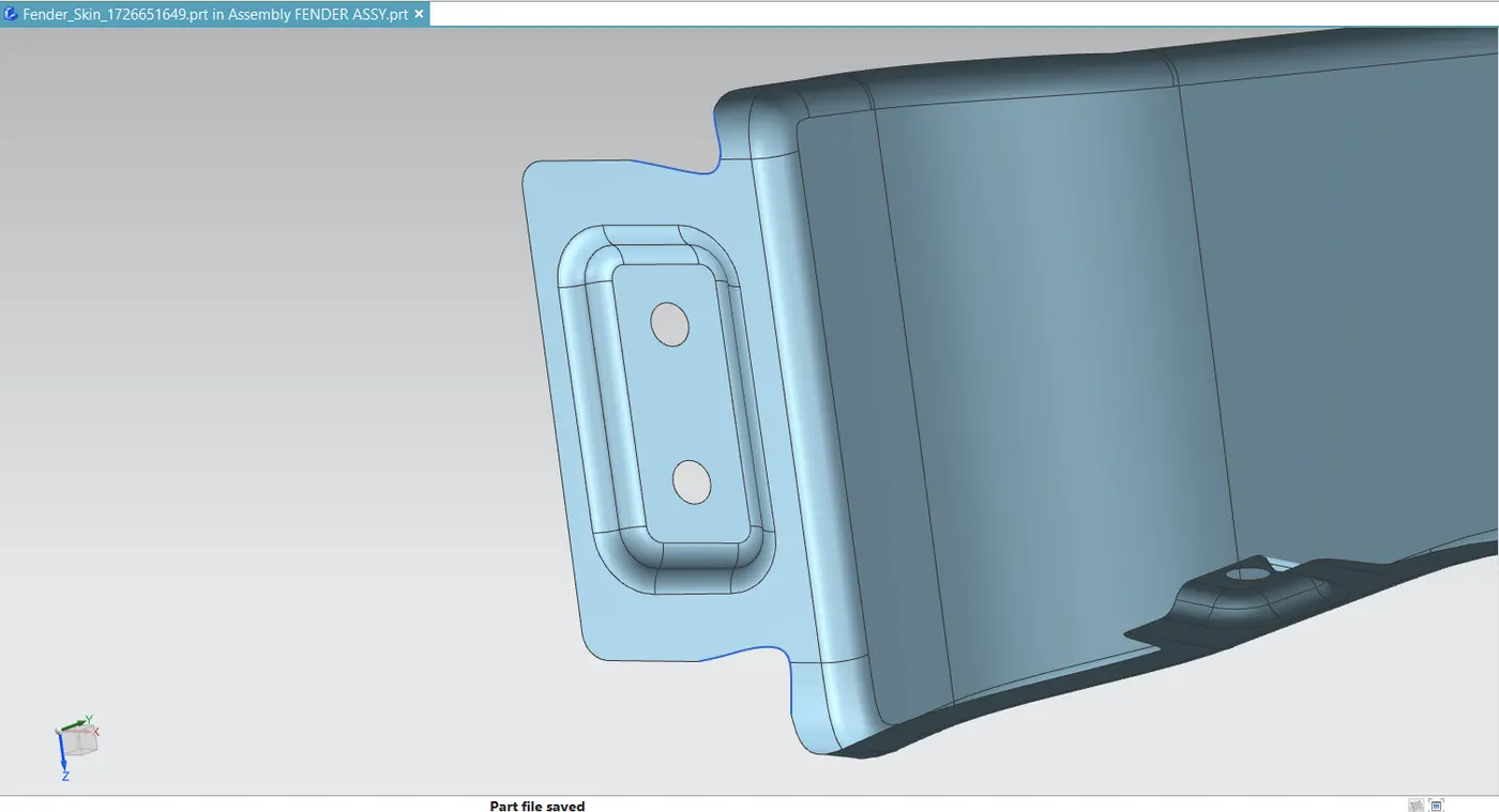
BUMPER MOUNTING AREA
Bumper mounting are is used to fix the plastic bumper to the fender with the help of the fasteners.
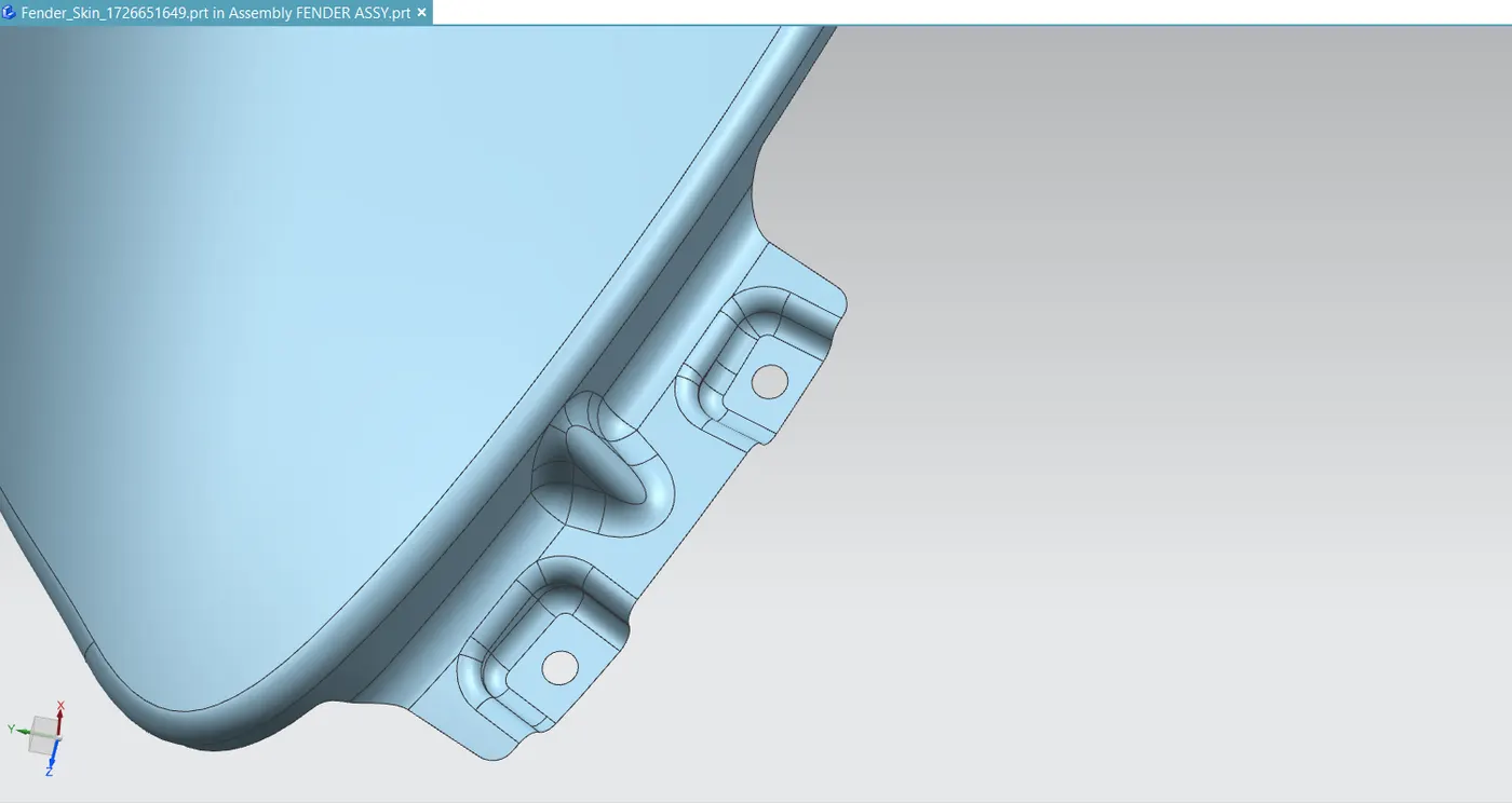
A-PILLAR MOUNTING AREA
The A-pillar is the structural pillar that combines the body to roof. This make the side of the wind shield rest. Front fender are fastened to the A pillar to form a robust structure.
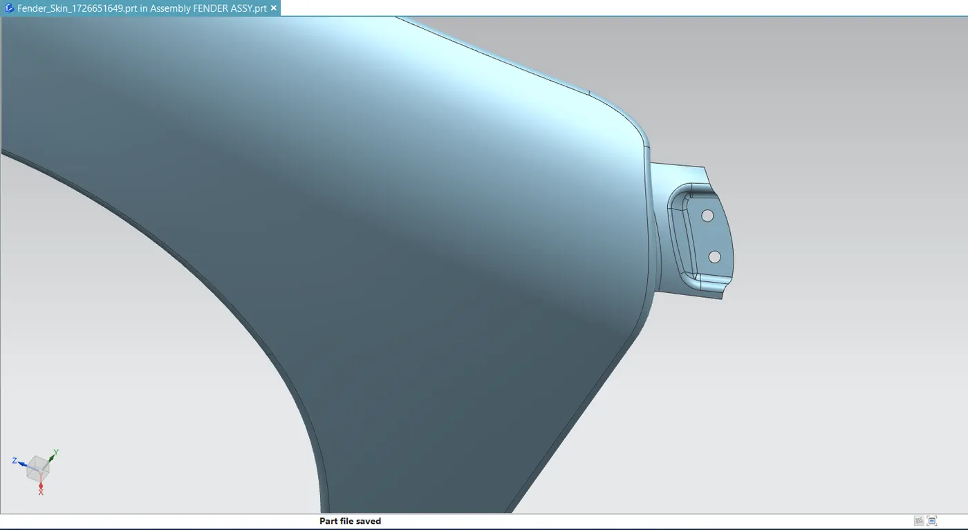
BAFFLE MOUNTING AREA
Baffle mounting or mudguard are clip fit type of mounting on the inner side of the fender arc over the tyre. It protects the car engine compartment and pedestrians from causing injuries from chip out the debris on the road when the car is in motion. They are mounted on the fender using a special type of locking clips which are made up of plastics.
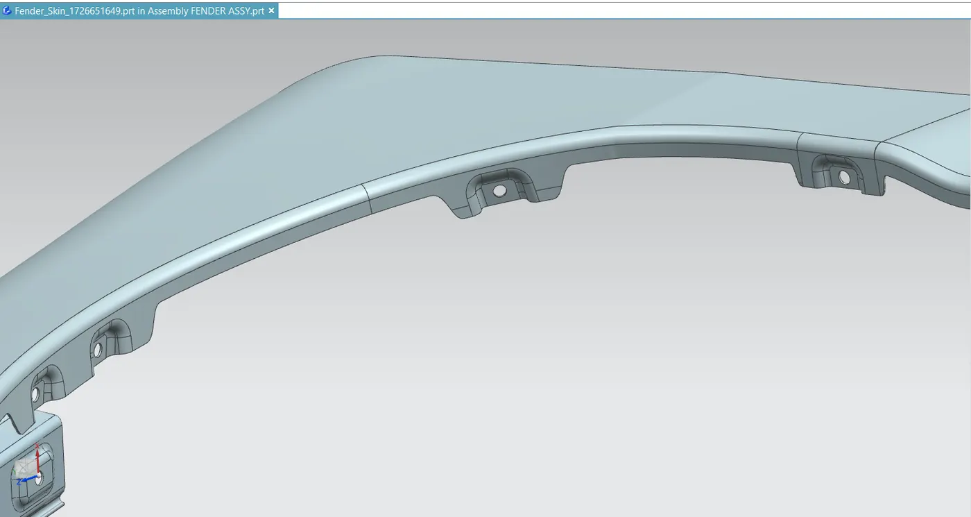
THICKENING OF THE SURFACE
The thickness of 0.75 mm inward on the final sewed surface of the fender to the Sheetmetal parameters.
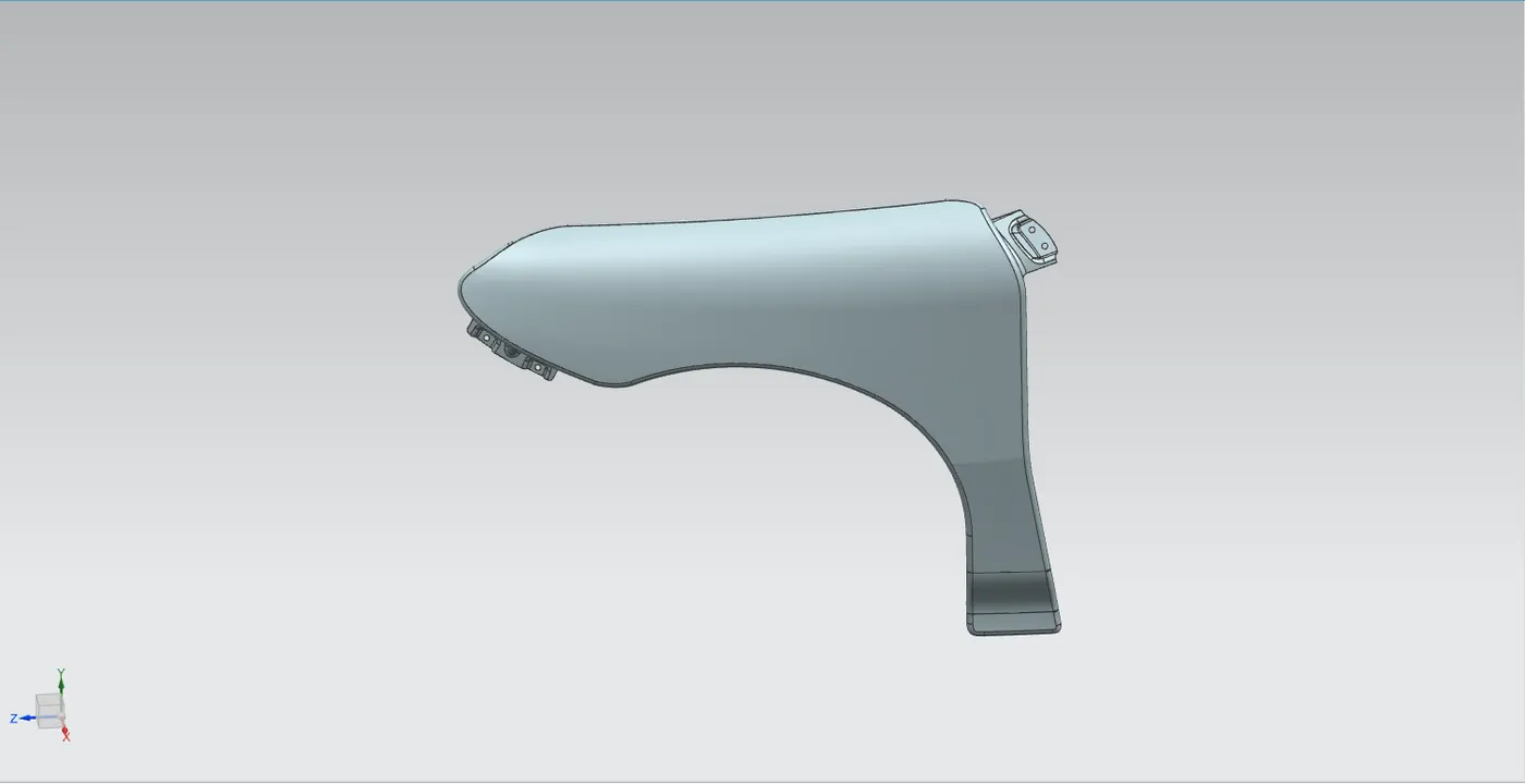
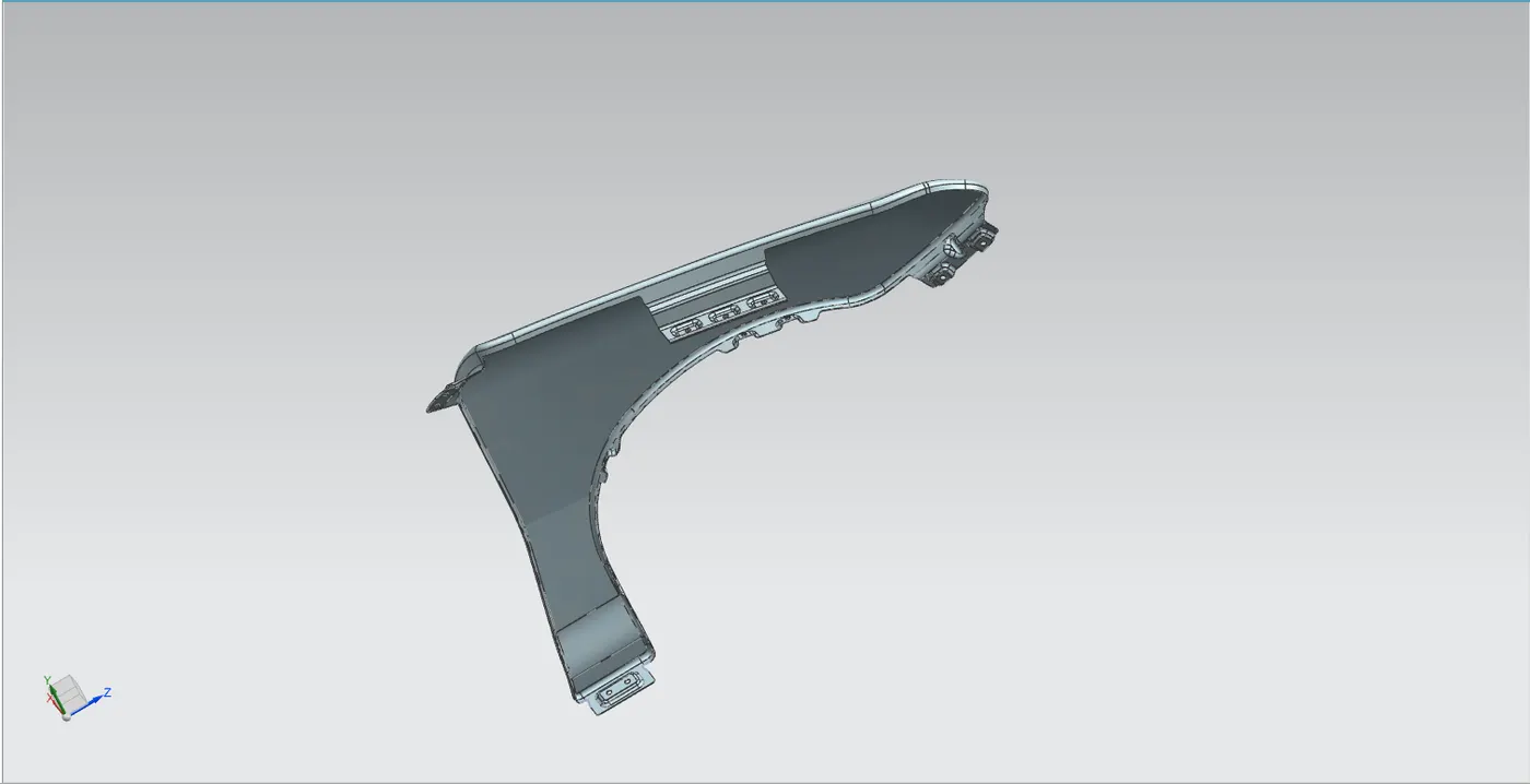
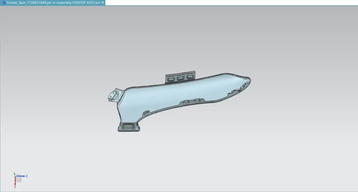
Different views of fender