Fender Design
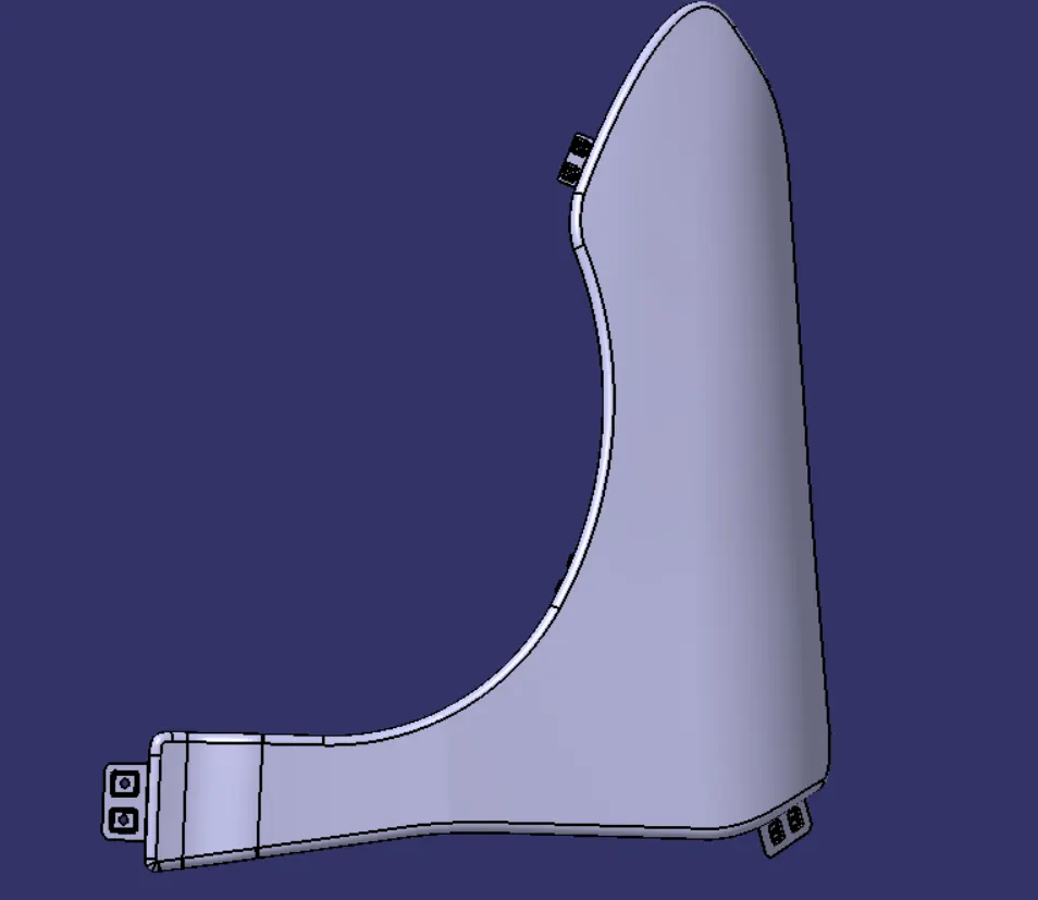
FENDER :
Fender is the American english term for the part of an automobiles, motorcycle or other vehicle body that frames a wheel well (the fender underside). Its primary purpose is to prevent sand, mud, rocks, liquids, and other road spray from being thrown into the air by the rotating tire. Fenders are typically rigid and can be damaged by contact with the road surface.
Fenders are an intricate sheet of metal covering the wheel well of your car.Fenders are designed in a manner to provide resistance against wind and other roadside debris.
1.Full fender type
Full fender type is traditional type fender where more material consumption is observed. This type of fender is used in old design of automobiles where it increases the overall weight and thus reduces the performance of car.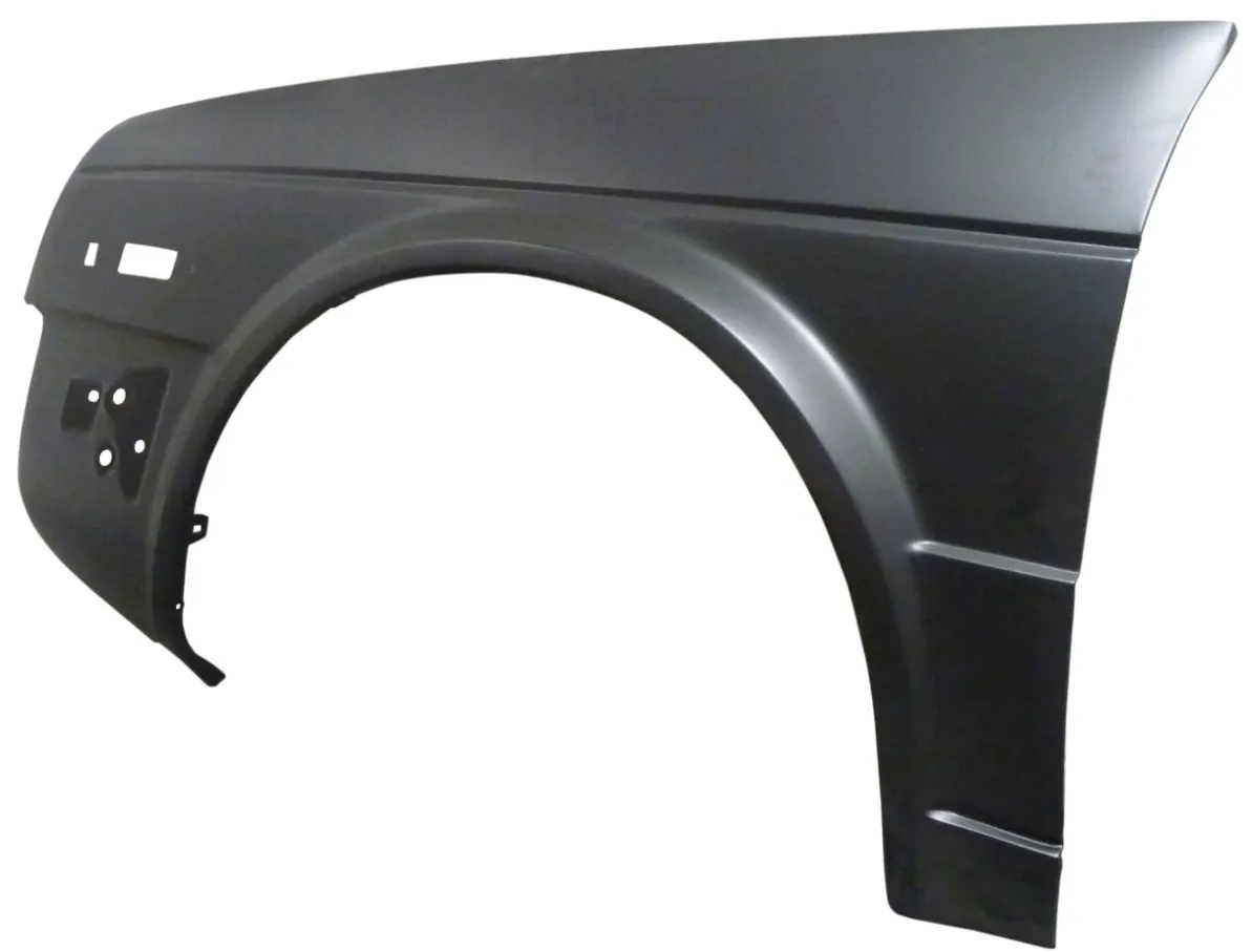
2. Half fender types
Half fender type is modern design where less material consumption is observed so productivity increases by reducing size of blank and thus providing more performance. The maintenance also relatively low compared to full bumper type.
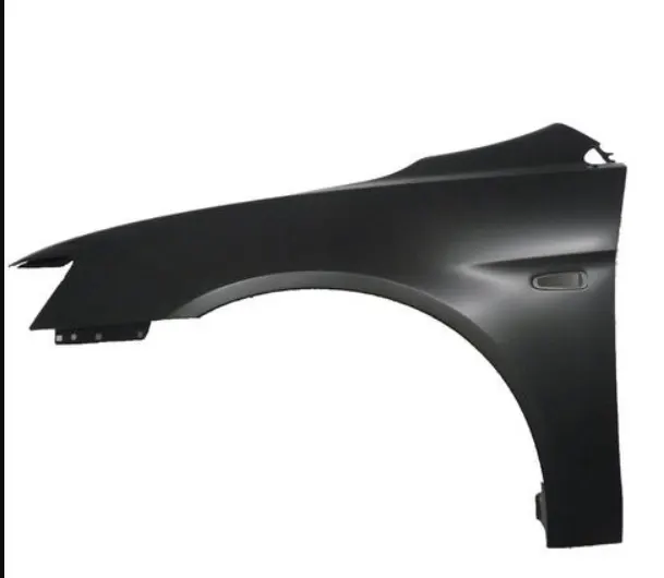
Fender Mountings essentials :
1. A Pillar Mounting
2. Bumper Mounting
3.Drip Area mounting
4.Baffel Mounting
5. Sill Mounting
Design the A Pillar
- First the skin data provided by the styling team needs to be extracted.Then the outer edge of the fender was offset inwards to particular length.Then by using the curve on surface command the unwanted portion were trimmed out using trim sheet.By using the law extension, the A pillar were extended and trimmed on the sides to get a flat edge.For creating a flat emboss which was used to mount the fender with the A-pillar a datum plane was created.Then the required sketch was drawn on the datum plane and projected to the surface.Then for creating a fastener hole which needs to be around 5 mm gap around it trim surface command were used.Then the required blends were added using face blend and edge blend.
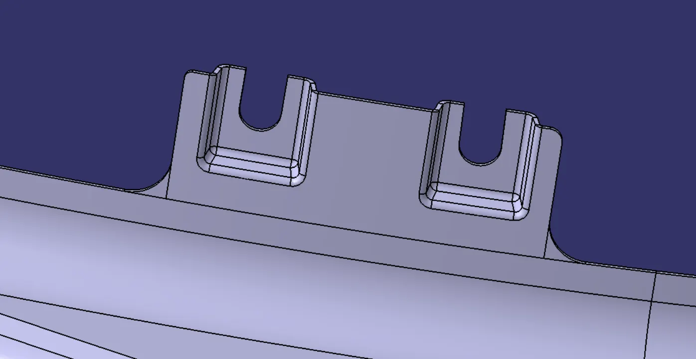
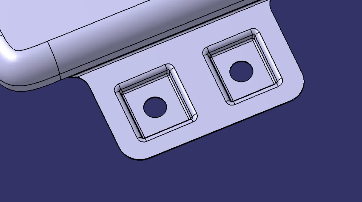
Design Bumper mounting
- The unwanted portions were trimmed off using curve on surface and trim surface command.
- Then for creating a flat surface emboss a datum plane was created.
- Then the required sketch drawn on the datum plane was projected to the surface and the required emboss were created.
- The holes were trimmed by using trim sheet after creating emboss.
- Emboss were created with a draft so that it satisfies the manufacturing requirements.
- Finally, the required blends were applied.
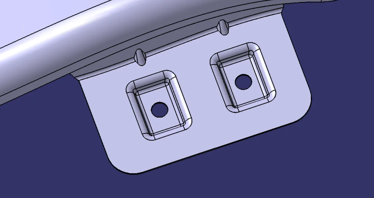
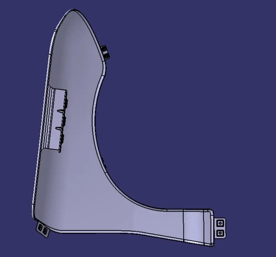
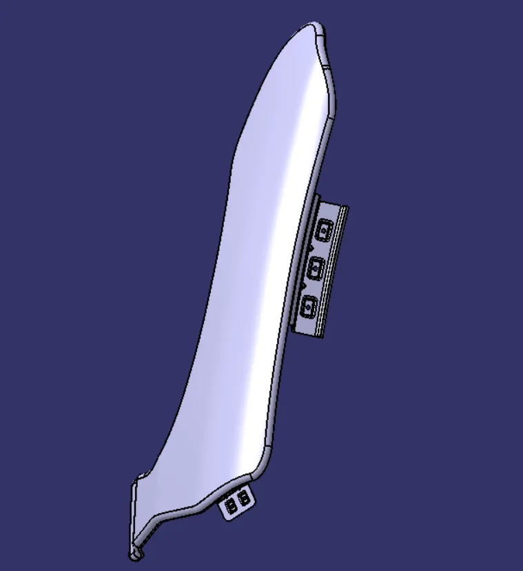
Design the baffle mountings.
- The baffle mounting was designed to fit a splash mounting on it which helps the engine compartment to protect it from the debris that entering in to while driving.
- For creating it three mounting areas were created with the required holes on it for the fasteners.
- For creating the holes, a datum plane was created on all three mountings and projected on to the surface.
- By selecting the required vector and deselecting the project on both side option the holes were created.
Design the drip area mounting
- By using the information in the master section provided the drip mounting were created.
- The drip area must be minimum 150 mm apart from the front edge so that the drip mounting won’t disturb the head lamp mountings.
- From backwards the drip area must be 200 mm apart from back edge to avoid the coincidence with the engine cables.
- For creating the drip area at the required distance two planes were created and then the intersection curve was used to create the curve on surface as required.
- Then the remaining unwanted portions were trimmed out.
- The design takes a vital role in avoiding the human eye seeing the insides of the car through the gap between the hood and fender.
- So the drip areawas created in particular angle as required by the master section the required emboss were created.
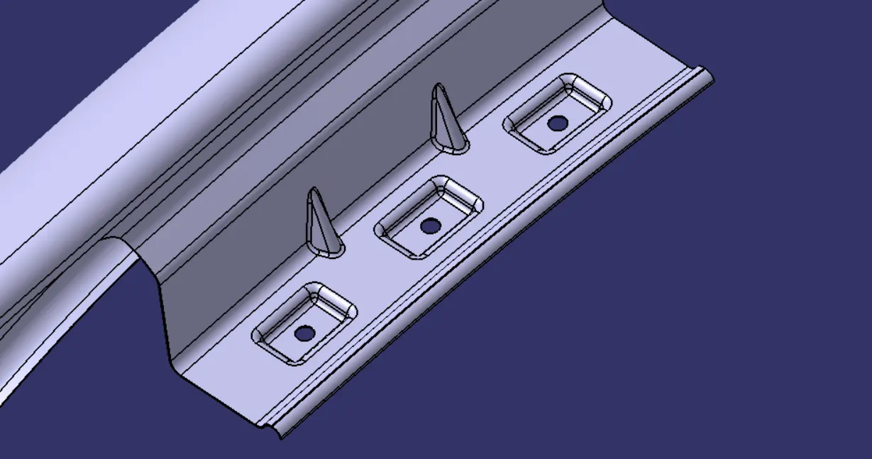
Design the sill mounting
- For creating the sill mounting the extra portions were trimmed out.
- Then the datum was created and the required sketch was drawn and then projected.
- Then emboss were generated and blended the edges together.
- The fastener holes were created by using the trim surface feature.