Fender Design
OBJECTIVE
Designing of car's fender using Nx cad software
FENDER
Front fender is a seperate part compared to back fender because it is intergrated with the body.Here we gave mounting part in sill area,bumper area,baffle area( spalsh absorbtion area), drip area and A pillar area.
While constructing drip area ( area near engine room) ; special requirement should be cinsidered compared to rest areas.
The drip area is made as per the diagram.thedrip area mounting surface starts from 200 mm away from the a pillar region.There also comes the whiper attachment area.So the mount should not affect the working and mounting of whiper in thier region and from bumper area it should be 150 mm away because headlight housing would be there .So no disturbance for attachment of headlight housing should be there.
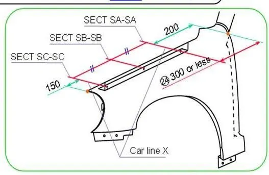
The figure below shows how the mounting surface aroung drip area should be.
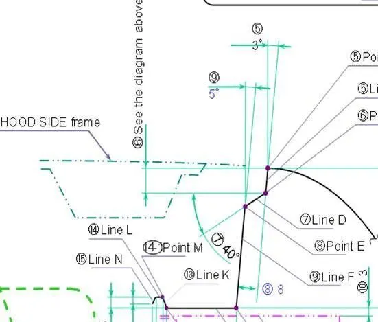
The flange should be 3 degree to vertical line.But we didn't made any change to the given flange.The line D shown in figure is taken as 8 mm inclined 40 degree to horizontal line as shown.The drip depth should not exceed 40mm because it affect productivity.Tooling won't be that easy it the lenghth exceed.Line F shown is build inorder to compensate the drip depth below 40mm.The line F is inclined for preventing visiblility inside hood area from the customer.
The link K is 25 mm lenghth which is already given.The inclined small surface shown is total lenght is 5 mm in horizontal direction.So considering angle shown ;it is made accordingly.The drip area's end region near to engine room should be 10mm or more distant from engine room.
Rest of the mounting surface are made without any special consideration like drip area.
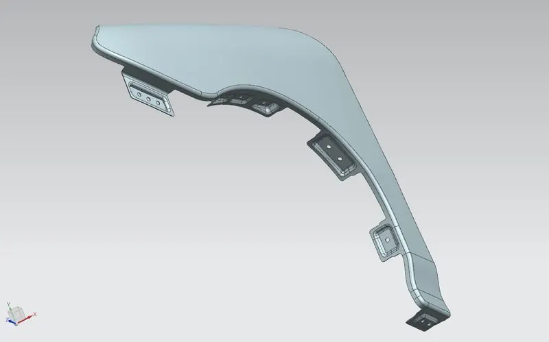
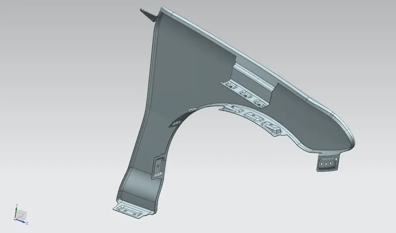
One main point to remember that the edge of the surface should not be sharp.so we gave edge fillet to the surface 3 mm.