Fender Design
AIM
To create the baffle mounting, sill mounting, bumper mounting, pillar mounting, drip area mounting according to the given master scetion of the given class A surface.
FENDER
Fenders is located extremely close together on a car but they have very different functions and appearances.
Appearance: Fenders are a curved strut which sits directly over the wheel well, so it hangs more over the wheels and off the side of the car. Quarter panels, on the other hand, are the panels which sit over fenders and help cover the area around the doors, trunk, hood, and wheels.
Function: Fenders are used to protect your car, both from things kicked up by the wheels and from side impact that might damage your wheels. A quarter panel, on the other hand, just covers a section of the frame on the side of the car and provides some extra protection from impacts.
Replacement: A fender is relatively easy to replace at home if you have the tools and knowledge to do so. A quarter panel attached to the frame of your car, however, and short of talking to a mechanic you will need to dismantle the side of your vehicle to get this panel off.
TYPES OF FENDERS
| s .no | Half bumper type | Full bumper type |
| 1 | 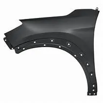 |
|
| 2 |
Half bumper type fender is used in nowdays cars. It's manufacturing cost is low and it is manufactured in such way that the waste of material is very less. |
Full bumper type is used in old cars. The manufacturing cost of this bumper is more and waste material is more in this type of fenders. |
| 3 |
The lighter the weight of the car higher the performance. |
Weight of this kind of bumpers will be bit more than half bumper type. |
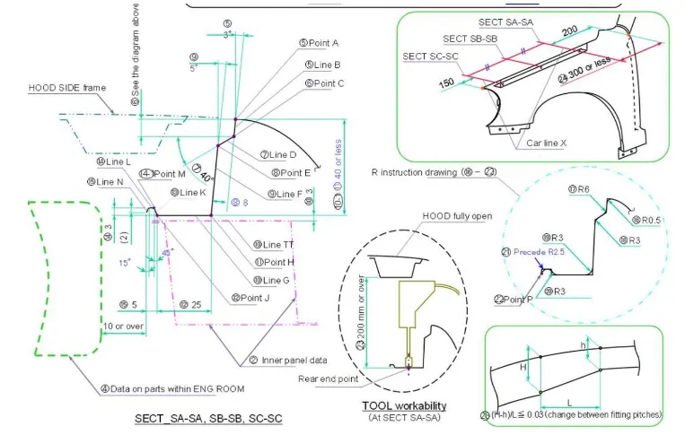
MASTER SECTION
DESIGN CONSIDERATION
1. We need to give 150mm gap from the head lamp position and 200mm from the A pillar area to position the drip area mountings. Drip area mounting will have several bends.
2. Engine components should not be visible from outside. For this purpose initially 3 degree of angle and suitable lenght should be provided.
FENDER MOUNTINGS
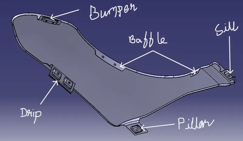
1. DRIP AREA
This is the area which comes inside the engine compartments.
We need to give 150mm gap from the head lamp position and 200mm from the A pillar area to position the drip area mountings. Drip area mounting will have several bends.
It has to made lengthier inside the engine compartment and it has to withstand more vibrations. It has a inverted v shape at the end of the flanges reason for this shape is reduce the frequency of the vibration while it is subjected to the vibrations.
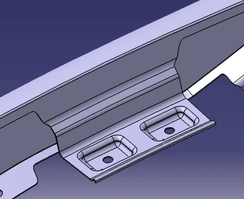
Beads are given in between two surfaces to encounter the spring back effect
Embosses are given in a large surface are to increaes the strength and for giving the space for the fasteners.
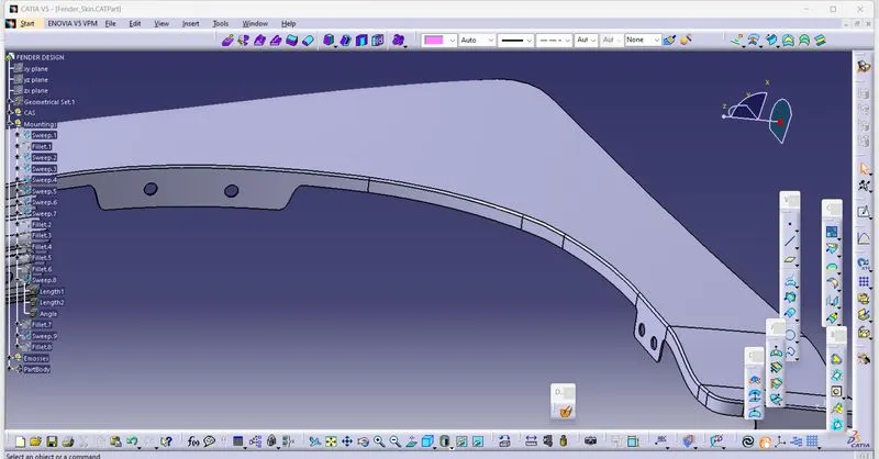
2. BAFFLE MOUNTING
In wheel arch area one plastic will be attatched is called asbaffle. Usually the amount of baffle will be differ with company to company.
We do not need larger flanges in this area for mount the plastics in this area.
Number of baffle mountings are calculated by the size of the fender, fender type and varies with company standards.
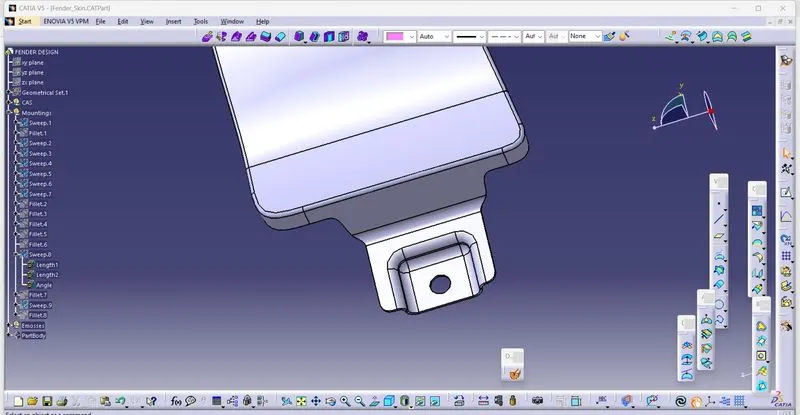
3. SILL MOUNTING
Sill mounting area is the bottom-most area of the fender. Here we do fanstening and a cover will be added in the bottom area to cover the fastening to improve asthetic look of the car
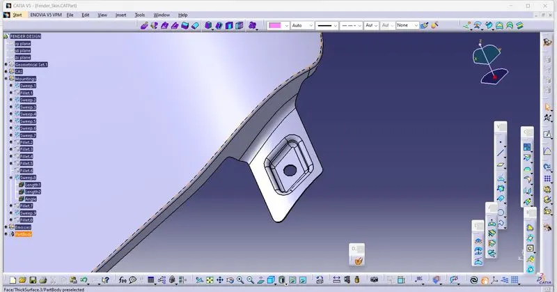
4. A PILLER MOUNTING/ COWL MOUNTING
This will get attatched at the cowl part. Cowl is the place where front glass is going to held.It should have enough strength to withstand load while the car is running. In this place A pillar is going to sit.
Embosses are given to increase the strength of the flanges and we have to make the bottom part of the emboss flat to have the proper surface area and contact surface between A pillar and fender.
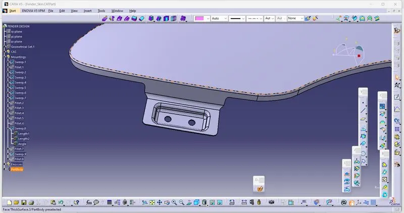
5. BUMPER MOUNTINGS
If it is a half bumper type bumper will get attatched at this place.
Half bumper type fender is used in nowdays cars. It's manufacturing cost is low and it is manufactured in such way that the waste of material is very less.
Full bumper type is used in old cars. The manufacturing cost of this bumper is more and waste material is more in this type of fenders.
MANUFACTURING PROSSES
These are the two major manufacturing process for creating fender and mountings.
1. EMBOSSING

the embossing is an auxillary sheet metal operation that is performed, using male and matching female dies, to increase the strength and also the stiffness.
Now, to see how the strength of the sheet metal we need to understand the stress-strain diagram shown below:
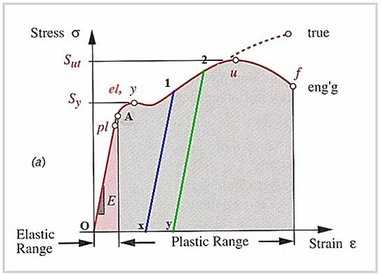
When the sheet metal is strained to any point upto the point marked pl , the stress is proportional to strain and if the stress is known the strain can be computed and vice versa, from the Youngs Modulus which is the slope of this curve. When the load is released it bounces back to original state and there is no permanent strain.
In the region between pl and el/y, the sheet metal is still elastic but stress and strain are not proportional. This represents the nonlinear elastic region. Let us assume the sheet is strained to the point A. Still, as it is elastic, when the load is released, the strain is released and once again there is no permanent strain.
Here pl is the proportionality limit, el is the elastic limit and y is the yield point.
Beyond the point denoted as el or y which represent the elastic limit or yield point, the sheet metal ceases to be elastic and enters the plastic region. When it is loaded to the point lets say point 1, and when the load is released, it follows the path shown in Blue colour. So there is a permanent set given by ox. When it is again loaded it follows the blue line and yields when the stress reaches the point 1. It is to be noticed that this stress is higher than the earlier stress,el/y, at which it started to yield. It looks as if the member has become stronger. Now if it sheet metal is loaded to a point, say 2 then the yield point once again shifts higher than the point 1. The metal when strained appears to become stronger and this region is referred to as the strain hardening region.
So in all the above applications as it is strained during the embossing process to a point beyond yield point the member appears to have greater strength thus giving it the capability to withstand higher loads without deformation.
Now stiffness of a structure is a property by virtue of which it resists deformation. This depends not only on the Material property ( E,or G) but also on the cross section dimensions. By changing the cross section there will be added stiffness thus making the member more resistant to lateral deformation.
2. BENDING
EDGE BENDING
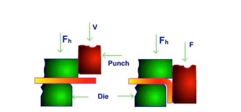
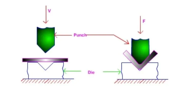
Bending of sheets and plates is widely used in forming parts such ascorrugations, flanges, etc. Bending is a forming operation in which a sheet metalis subjected to bending stress thereby a flat straight sheet is made into a curved sheet. The sheet gets plastically deformed without change in thickness. Die andpunch are used for bending. If a v shaped die and punch are used, the bending is called v-bending. If the sheet is bent on the edge using a wiping die it is called edge bending. In this process, one end of the sheet is held like a cantilever using a pressure pad and the other end is deformed by a punch which moves vertically down, bending the sheet. Usually, edge bending is done in order to obtain an angle of 90o.
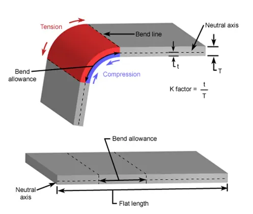
During bending of a strip, the material outward of the neutral axis is subjected to tensile stress. Material inside is subjected to compressive stress. Bend radius R is the radius of curvature of the bent sheet inside the bending. The neutral axis remains at the center of the thickness of the sheet for elastic bending. For plastic
bending, however, the neutral axis shifts towards the inside of the bend. The rate of elongation of outer fibers is greater than the rate of contraction of inner fibers. Therefore, there is a thickness reduction at the bend section.
CONCLUSION
Thus the front fender has been successfully designed according to the given master section, and baffle mounting, sill mounting, bumper mounting, pillar mounting, drip area mounting are made by following design rules for sheet metal.