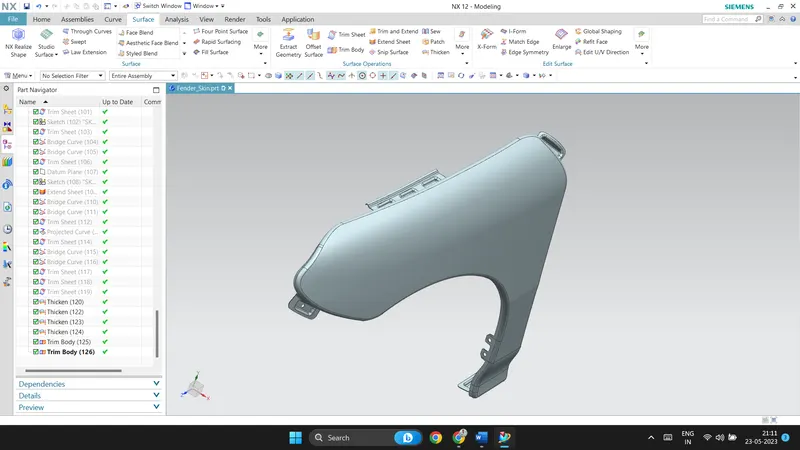
Fender Design
FENDER DESIGN
Aim:
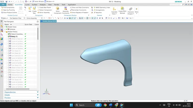
To create mountings on the fender for the drip area, ‘A’ pillar, bumper and the sill area. This challenge is provided with skin data of the fender. A master section is also provided for the drip area.
Fender:
Fender acts as a cover for the engine and also acts as a hub for the wheel. It provides good aesthetics to the car and also prevents damage to the engine from pebbles, dirt and mud. A fender also provides protection for the pedestrians when met with accident. It acts as a flexible body rather than a rigid body, thus distributing the forces away.
Types of fenders:
- Full bumper type fender
- Half bumper type fender
The picture below shows the major difference between the two types of fenders. Full bumper type requires more material than the half bumper type. This is the main reason to shift from full bumper type to half bumper type. Mostly all the modern cars use half bumper type fenders.

In the previous challenge, wheel arch standards and regulations for different countries has shown. In this challenge mountings are created on the fender to connect sill, bumper, hood and A pillar.
Fender design:
The skin data for the fender is provided along with a master section for the drip area. The design should follow the master section provided. The design begins with working on the A pillar mounting and drip area. Curve on surface tool is used to get the desired curves on the surface. Using trim command, the unwanted surfaces are trimmed off. Law extension is used at A pillar mounting, sill mounting and at bumper mounting to create embosses.
Drip area:
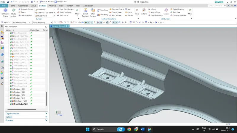
The image given below shows the drip area of the fender. Three embosses are created for three fasteners. The embosses need to have flat bases, this is because when fender is attached to other parts it will have firm attachment. To design drip area, we have certain rules to follow, from A pillar it should have 200mm clearance and from the headlight area it should have 150mm clearance. A datum plane is created on the drip area, a sketch is created with necessary geometrical constraints. Further the embosses are created based on the sketch using emboss command in surface menu. Fillets are provided at all the necessary faces. The drip area is also provided with darts to support and to add strength. Holes on the embosses are created with 5mm radius. According to the design rules the holes should have 10MM clearance around the hole. The entire drip area is designed by following the master section.
A pillar mounting area:
A pillar area mounting is created by extending the sheet perpendicular to the surface, using law extension command. A datum plane is created on the extended surface to create emboss. This surface is a curvy surface, so the datum plane is created with offset. A sketch is created to project on the surface with desired geometric constraints. Using emboss command, emboss is created with 10degree draft angle. The holes are made along the direction of the vectors. The edges of the part is trimmed to have smooth curves, for better manufacturability.
Sill mounting area:
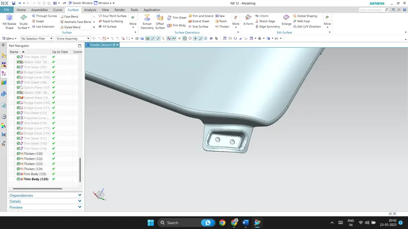
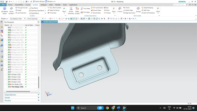
The bottom of the fender will get attached to sill, so the design should have a sill mounting area on the fender. To create sill area the sheet is extended, a datum plane is created on the surface. Embosses is created on the surface by the sketch created using emboss command. Using trim sheet command holes are made for the fasteners with 5mm radius. Sharp edges are provided with reliefs. The image below gives the clear picture of the sill mounting area design.
Bumper mounting area:
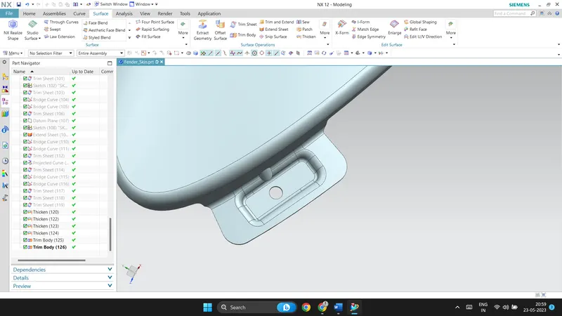
The front part of the fender is attached to the bumper of the car, a bumper mounting is designed on the fender as shown below. Using law extension command the surface is created perpendicular to the fender. A datum plane is created on the surface using three-point datum plane. A sketch is created with desired geometry and also provided with necessary constraints. Further emboss is created on the surface along with a hole with 5mm radius. A dart is also created at this area to provide strength to the part.
Baffle area:
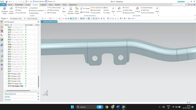
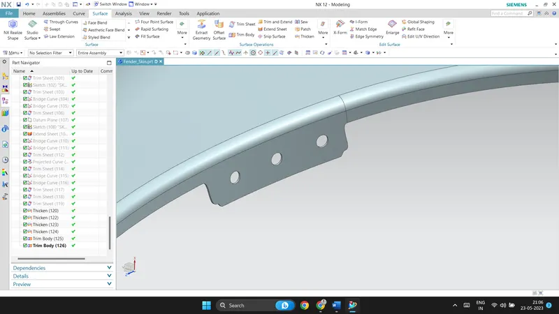
Two set of mountings are created for the baffle area. Images below clearly represents the design. The sheet is extended to have clearance for the holes created on the surface. Using trim sheet command holes are created along the direction of the vector.
Conclusion:
The fender design is completed by creating all the necessary mountings on the fender. The created sheet is further thickened to 0.75mm. All the faces are filleted, its very important not to have any sharp edges on the part. All the sharp edges are either given relief or made it into smooth curved shape. With all the design rules a fender is designed.