Fender Design
Fender Design Report: Challenge 6
Overview
In this challenge the main objective is to complete the given Fender Class A with appropriate mountings and surface characteristics as a thickened part. Also we focus on creating a proper drip Area for the fender to attach it to the Engine compartment following the rules of drip area creation.
Given Image
Procedure : A-pillar, Bumper ,Sill Mounting Creation
- We see that the fender surface comes attached with a flange of certain length. Now, we offset a line on that flange onto the flange itself at 5mm offset.
- We create “curves on surface” at different regions as boundaries where we need mountings .EXAMPLE: At A pillar location, at Sill, Bumper mounting etc.
- These curves are created with tangency to the lines they join at their starting and end points respectively for smooth curvature and ease of manufacture.
- Then we trim the fender surface at these boundaries. Later at each free edge we create a law extension perpendicularly for a certain length.
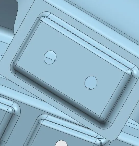
- Now we draw a sketch of the mounting on a plane, on or parallel to the law extension surface with holes in it.
- Then this sketch is embossed with datum plane and we get a flat emboss of 3.5mm offset from plane (if plane on law extension surface).
- Then holes in the sketch are trimmed with the sheet along vector direction and face and edge blends are added for proper surface condition and curvature.
Procedure: DRIP AREA Creation
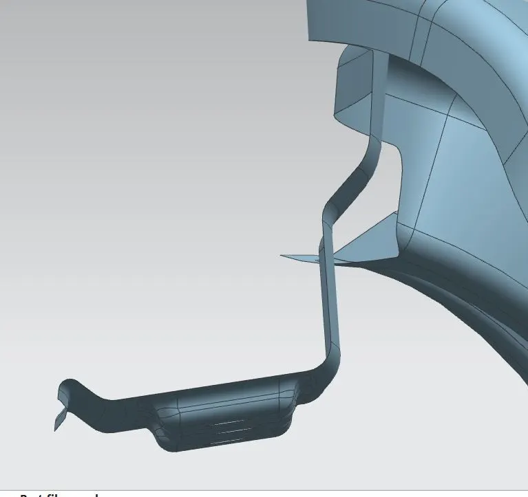
- In the drip area creation segment we first analyze the given image for the different angles , length and fillets associated with creating the different flanges involved in creating the drip area.
- To identify the linear length on the fender where the drip area would cover we create two datum planes using line/point references on either side and offset them.
: approximately 150mm from front.( Space for Headlamp mounting)
:approximately 200mm from back (Space for Cowl top Mounting)
- At this juncture we create curves on surface with proper curvature for trimming the flange and then proceed to drip area creation.
- We use Law extension at every lower-free boundary with proper length and angle as mentioned in the “Given Image” picture to create surfaces of the drip area.
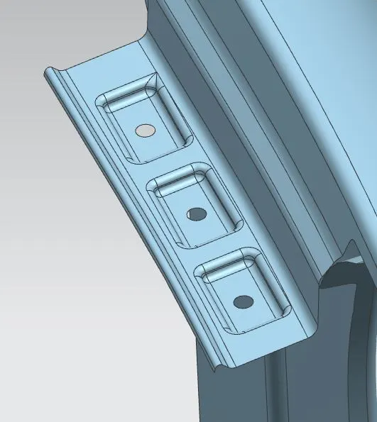
- Now we use face and edge blends to sew and give proper fillets to sharp corners.
- Later the mountings with proper flat emboss and weld holes are created as said in the previous procedure.
Finally two or more “darts” are added at the bumper mounting for increasing the strength of the attachment. Also they are added at the drip area to prevent it form wobbling/ vibrating when the car is in motion.
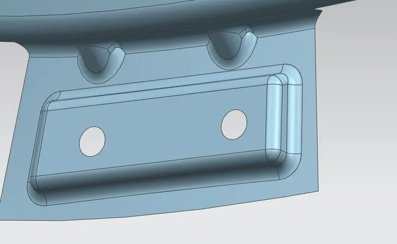
Later the part is thickened to 0.75mm on the inside to form a solid and any and all sharp edges are smoothened using edge blend.