Fender Design
AIM
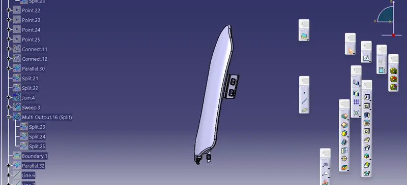
Aim is to design the fender model with the neceessary mounts using the class a surface
MOUNTS
- BUMPER
- A-PILLAR
- SILL
- COWL
- DRIP
THEORY
FENDER
it is apart of an automobile that frames a wheel well . its a primary purpose is to prevent sand , mud , rocks ,liquid and other roads spray the fender opening for the wheel wells tends to be much larger than the diameter of the tire becauz they do not move with tire suspension aon the suspension nd consequently must be large enough to allow the full range of tire suspension and consequentlymust be large enough to allow the full range of motion on the on the suspension without touching the interior of the wheel well
TYPES OF FENDER
FULL FRONT FENDER
if the fender covers the tire ,the wheel well surrounding the tire , and it is not directly visible from above the car body .it increase the weight and scrap of the component
HALF FRONT FENDER
it reduce the weight and scrap . it creates only half of the full front fender does and the other part is created with the bumper part
PROCEDURE
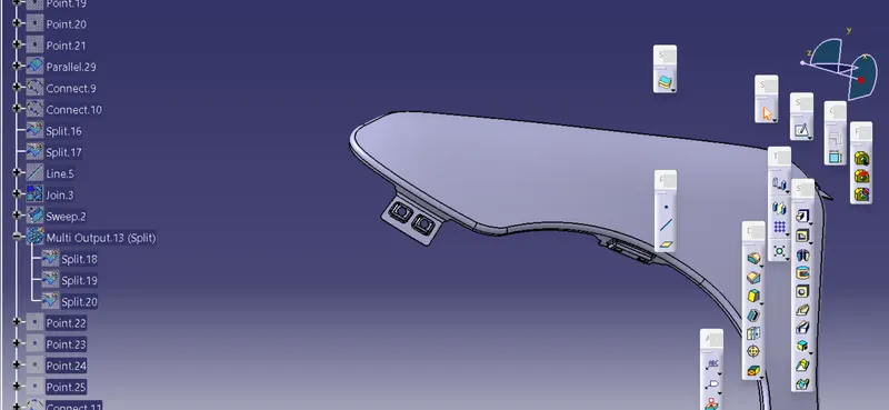
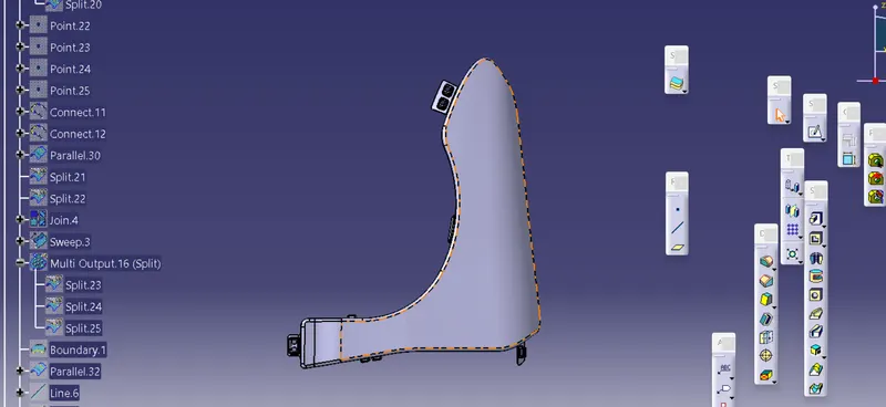
- Check the model and create the the mount area layout
- use parrellel curve option to offset line to 5mm and cut the class a suurface to create the space for the mounting
- Now join the split suface excluding the top surface
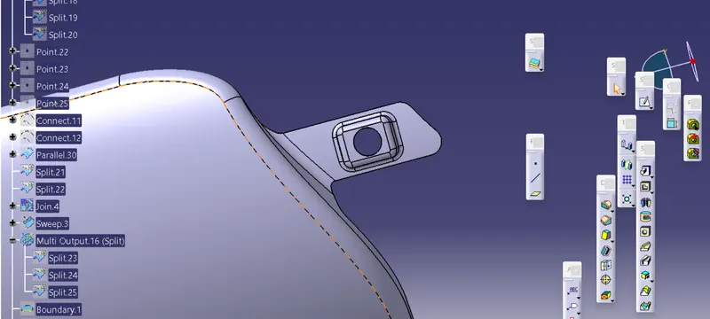
- now to create the mount region use the sweep option near the space created for the mounting
- after the sweep is done as per the design model join the surface
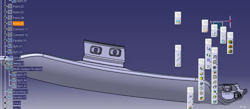
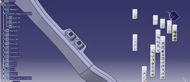
- after the mount is created we need to create embosses and hole are are to be given
- to create emboses create sketch with required shape .project the sketch onto the mounting area before that extract extract the surface
- now split the surface to create a hole near the projected area to create an embosses
- use the sweep command near the cut section now offset the extracted surface
- trim the surface together and create a relief hole which is given to such that the screwis fitted into that hole
- for the dip mount part ,follow the detail given and design the product
- to create beaks,create the surface in a way that is angular and then trim the surface together
- once the surface is trimmed , give the fillets near embosses and beads .
- use the extrude command followed by the edge fillet to create the sharp edges fillet to create the sharpedges to the curved parts near mountings
- after the surface is created , go to the part workbench and define the part body
- use the thickl surface option to create the solid with a thickness of 0.75 mm
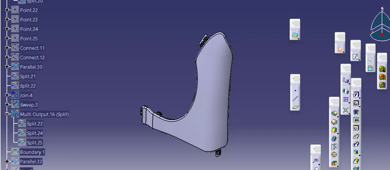
RESULT