Exhaust Port Challenge
REPORT:
AIM:
To perform a conjucate heat transfer(CHT) analysis for an exhaust manifold of an I.C Engine.
OBJECTIVES:
- To simulate the exhaust air in exhaust manifold.
- To find out the area where is the maximun heat transfer.
- Effect of coarse and fine mesh.
- Adding inflation layer to the boundary to get the accurate heat transfer Coefficient.
THEORY:
CONJUCATE HEAT TRANSFER:
The Conjugate Heat Transfer (CHT) analysis type allows for the simulation of heat transfer between solid and fluid domains by exchanging thermal energy at the interfaces between them. Typical applications of this analysis type exist as, but are not limited to, the simulation of heat exchangers, cooling of electronic equipment, and general-purpose cooling and heating systems.
WHY AND WHERE CHT ANALYSIS IS USED:
The term conjugate heat transfer (CHT) is used to describe processes which involve variations of temperature within solids and fluids, due to thermal interaction between the solids and fluids. The exchange of thermal energy between the two physical bodies is called study of Heat Transfer, the rate of transferred heat is directly proportional to the temperature difference between the bodies. A typical example is the heating or cooling of a solid object by the flow of air in which it is immersed and some other example includes conduction through solids, free and forced convection in the gases/fluids and thermal radiation.
Conjugate heat transfer corresponds with the combination of heat transfer in solids and heat transfer in fluids. In solids, conduction often dominates whereas in fluids, convection usually dominates. Efficiently combining heat transfer in fluids and solids is the key to designing effective coolers, heaters, or heat exchangers. Forced convection is the most common way to achieve high heat transfer rate. In some applications, the performances are further improved by combining convection with phase change (for example liquid water to vapor phase change).
Heat transfer in solids and heat transfer in fluids are combined in the majority of applications. This is because fluids flow around solids or between solid walls, and because solids are usually immersed in a fluid.
APPLICATION AND USES OF CHT ANALYSIS:
The fluid flow and heat transfer problems can be tightly coupled through the convection term in the energy equation and when physical properties are temperature dependent. While analytical solutions exist for some simple problems, we must rely on computational methods to solve most industrially relevant applications.
CHT can be performed to improve cooling performance of the water jacket and increase engine life. Advancements in cooling for applications such as gas turbines components require improved understanding of the complex heat transfer mechanisms and the interactions between those mechanisms, which our engineers can perform without hassle. Critical cooling applications often rely on multiple thermal protection techniques, including internal cooling, external film cooling, etc. which are efficiently used by our analysis to cool components and limit the use of coolant. We do extensive support for Motor and Battery CHT Analysis to get optimized design for High voltage systems. Conjugate Heat Transfer analysis provides the temperature distribution in solid and coolant of the engine and clear insight on velocity distribution and mechanism of heat transfer of coolant. Results of CHT analysis become input to structural simulations as thermal loads.
We have a wide experience in Engine CHT Analysis for various type of engines like Bikes, Passenger Cars, Racing cars, Commercial Vehicles, Marine, Agricultural equipment and Earth-moving equipment etc.
Efficiently combining heat transfer in fluids and solids is the key to designing effective coolers, heaters, or heat exchangers.
The fluid usually plays the role of energy carrier on large distances. Forced convection is the most common way to achieve high heat transfer rate. In some applications, the performances are further improved by combining convection with phase change (for example liquid water to vapor phase change).
Even so, solids are also needed, in particular to separate fluids in a heat exchanger so that fluids exchange energy without being mixed.
EXHAUST PORT:
The passage in the cylinder head which connects the exhaust valve and the exhaust manifold . The exhaust gases pass through the port to the exhaust manifold or header . On two-stroke engines the exhaust port is cut into the cylinder wall because it does not have valves.
PROCEDURE:
GEOMETRY PREPARATION:
SPACE CLAIM:
We import the solid component into ansys spaceclaim and extract the fluid and solid domain. Then both the component is combined into an single component, and we enable the share topology.
We do this in order to share the details between the solid and the fluid.
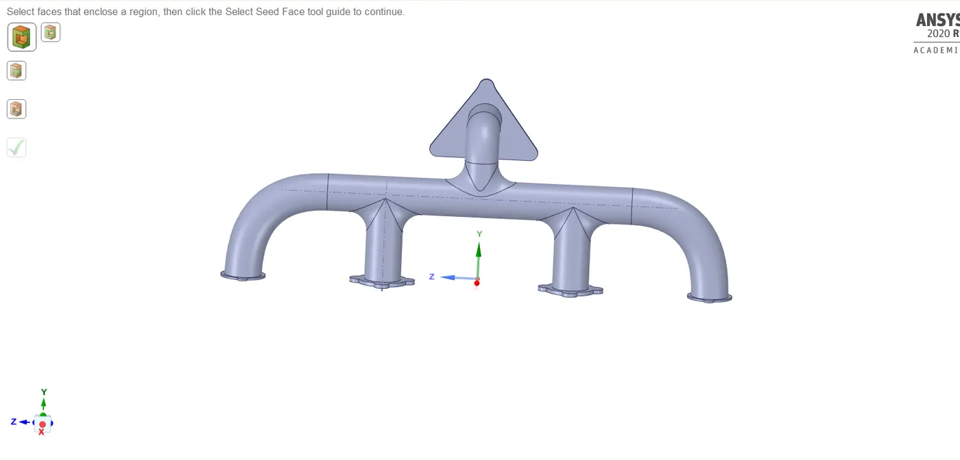
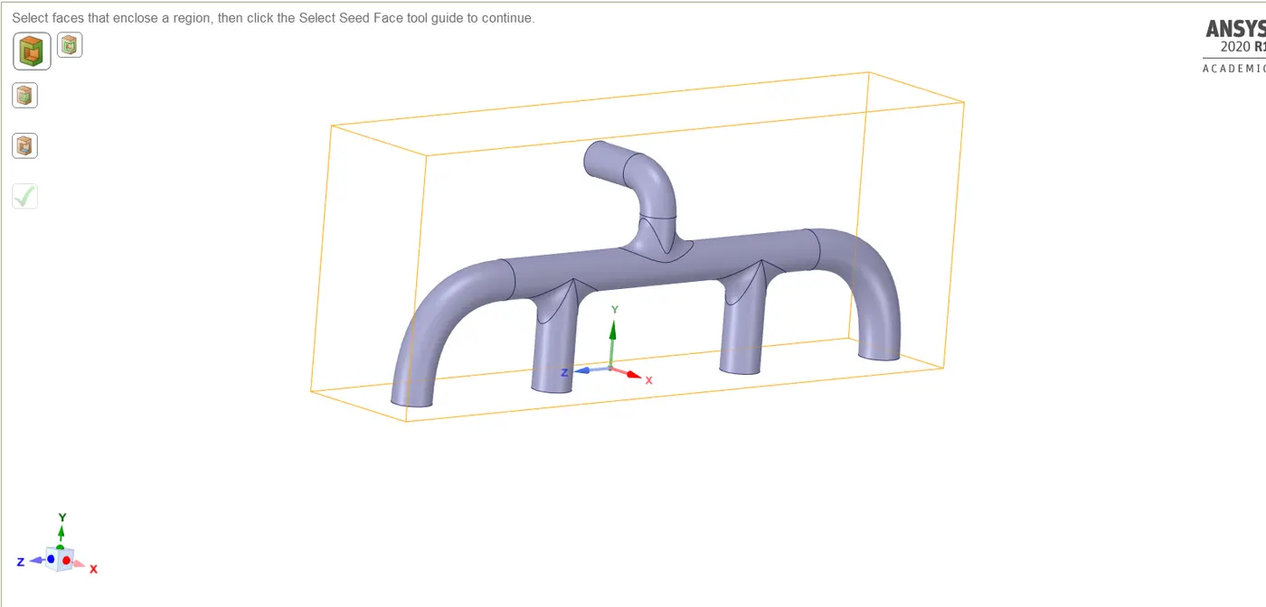
The below image represents the volume domain.
CASE 1 (Baseline Mesh):
No.of.elements:
MESH:
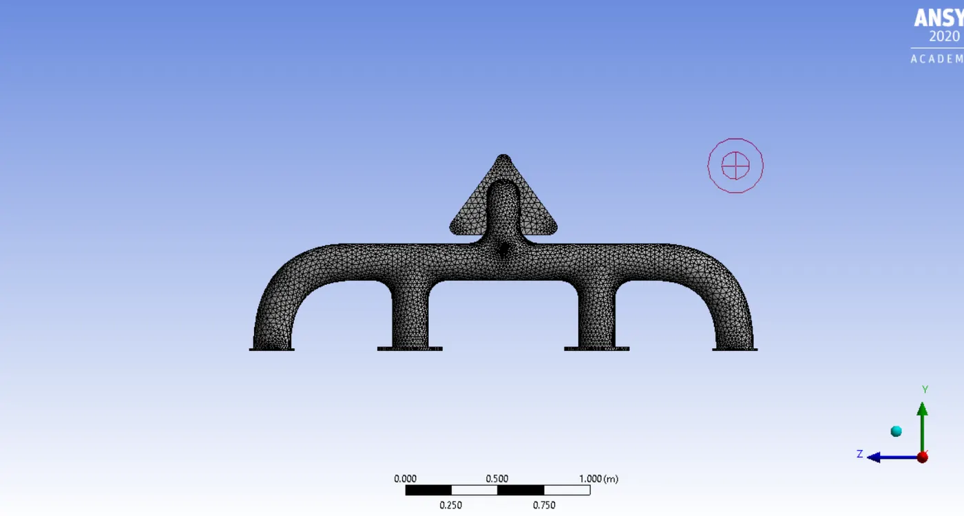
Using the named selection option give names to the inlets, outlet and the outer wall.
Now click on generate mesh option.
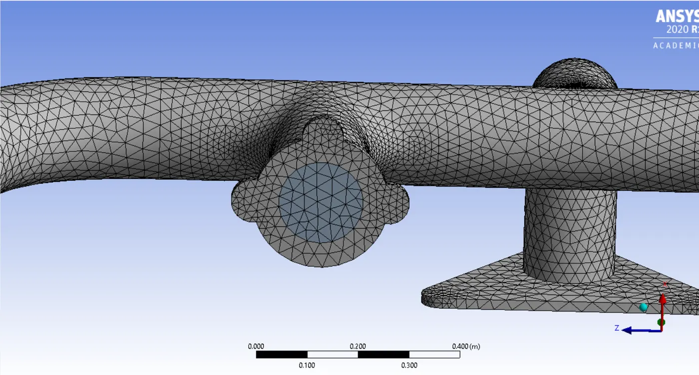
The below image represents the mesh structure of the component.
MESH QUALITY:
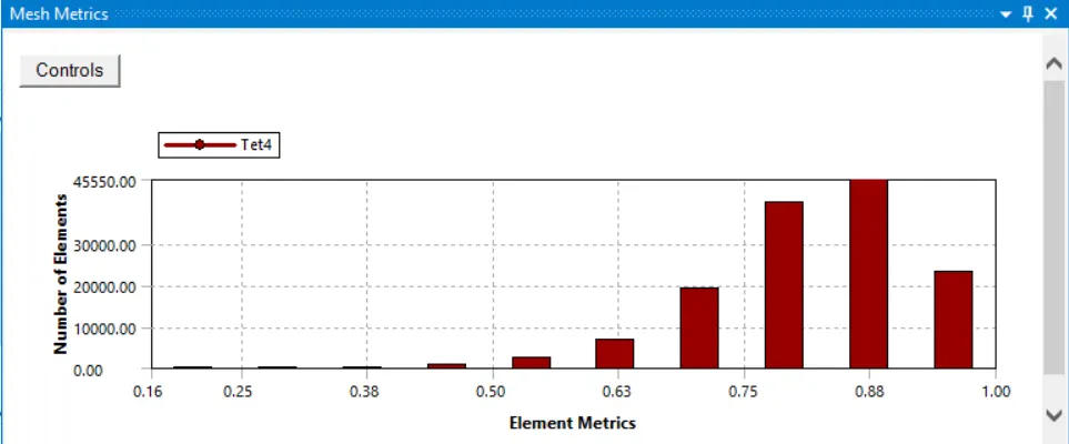
The bove mesh quality shows that the quality is not below 10%. Hence the mesh is of good quality.
SET UP:
We are using a pressure based solver. We will be solving the energy equation and using K-epsilon turbulenece model. The material used for the fluid is air and the solid material is aluminium.
Setting up boundary conditions.
Click on boundaries and select inlet, Give the inlet condition as 5m/s and initial temperature as 700k.
Now select the outer wall in boundaries and select convection and give the value as 20`frac{W}{m^2} K`
Now select hybrid initialization and give no.of.iterations and hit calculate.
RESULTS:
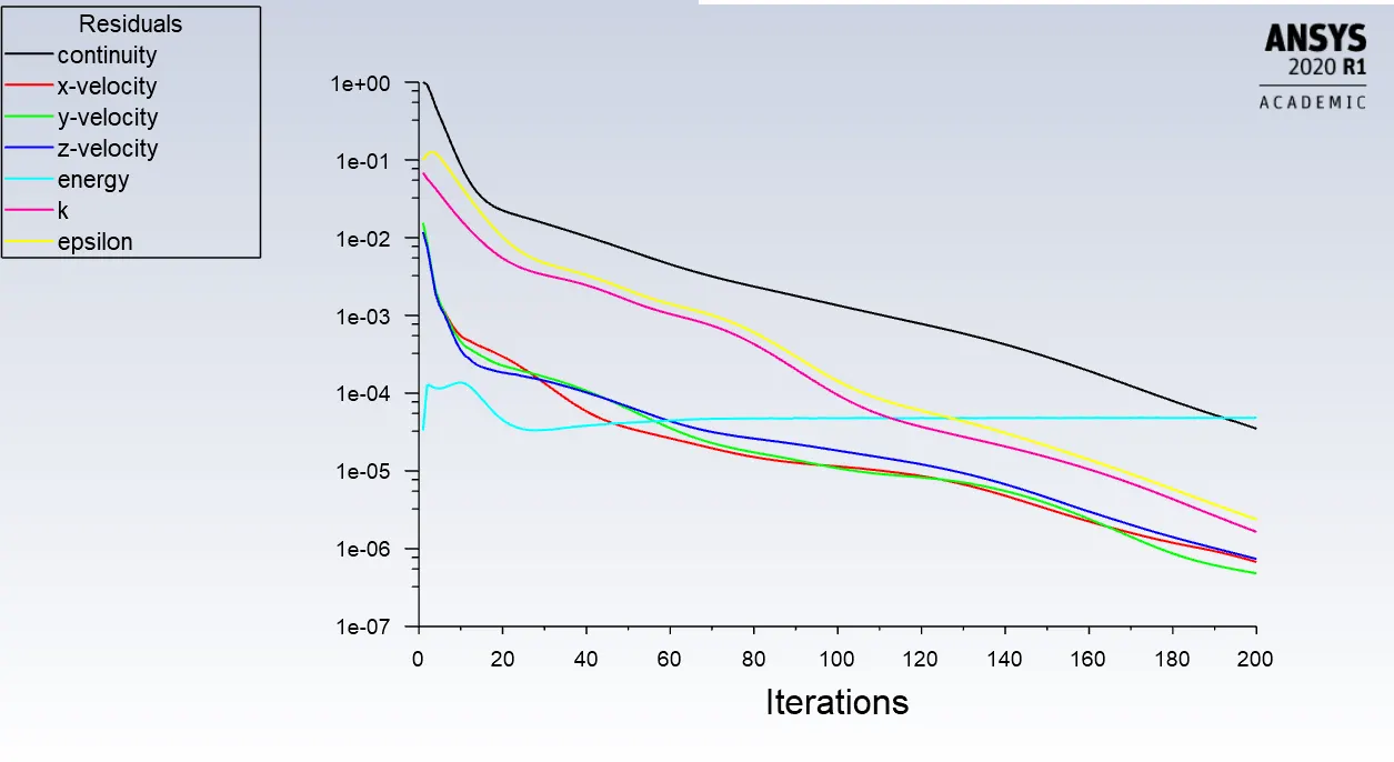
RESIDUAL GRAPH:
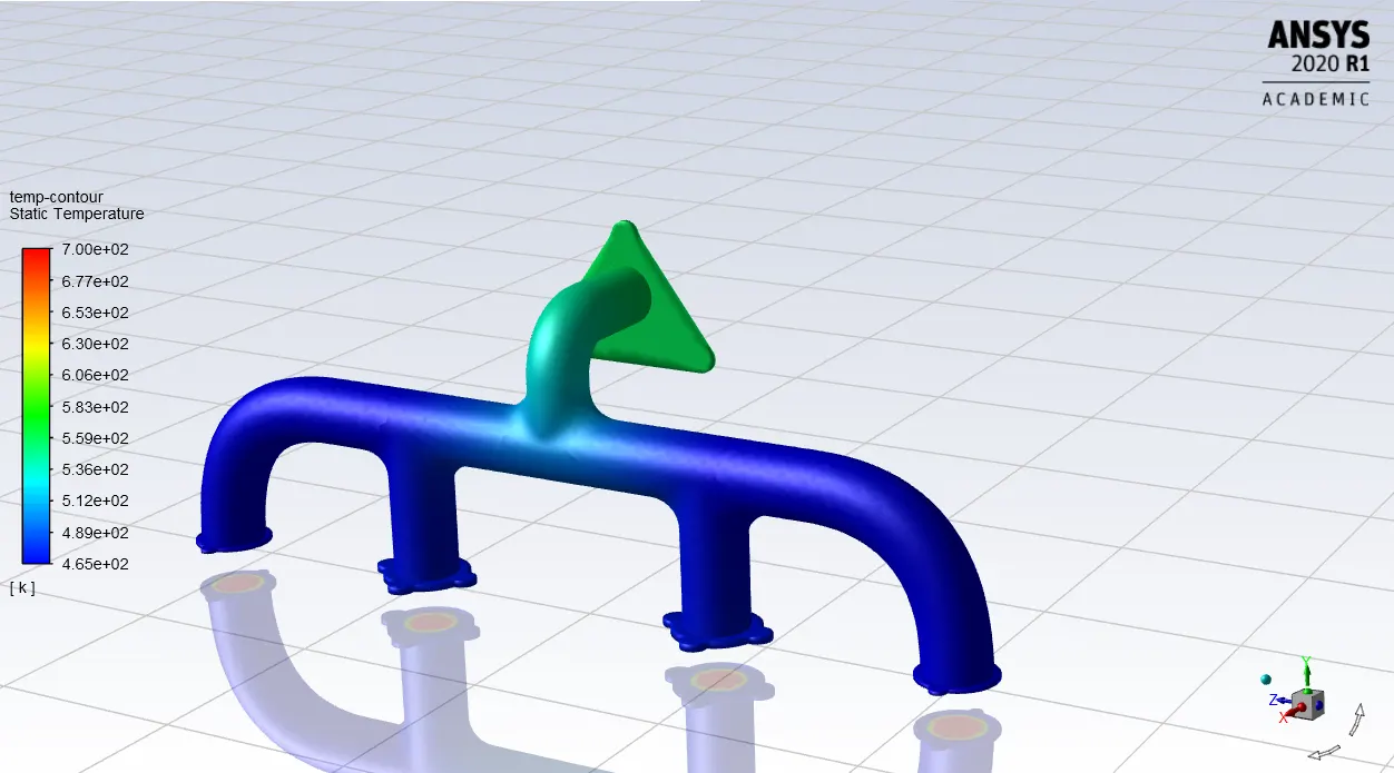
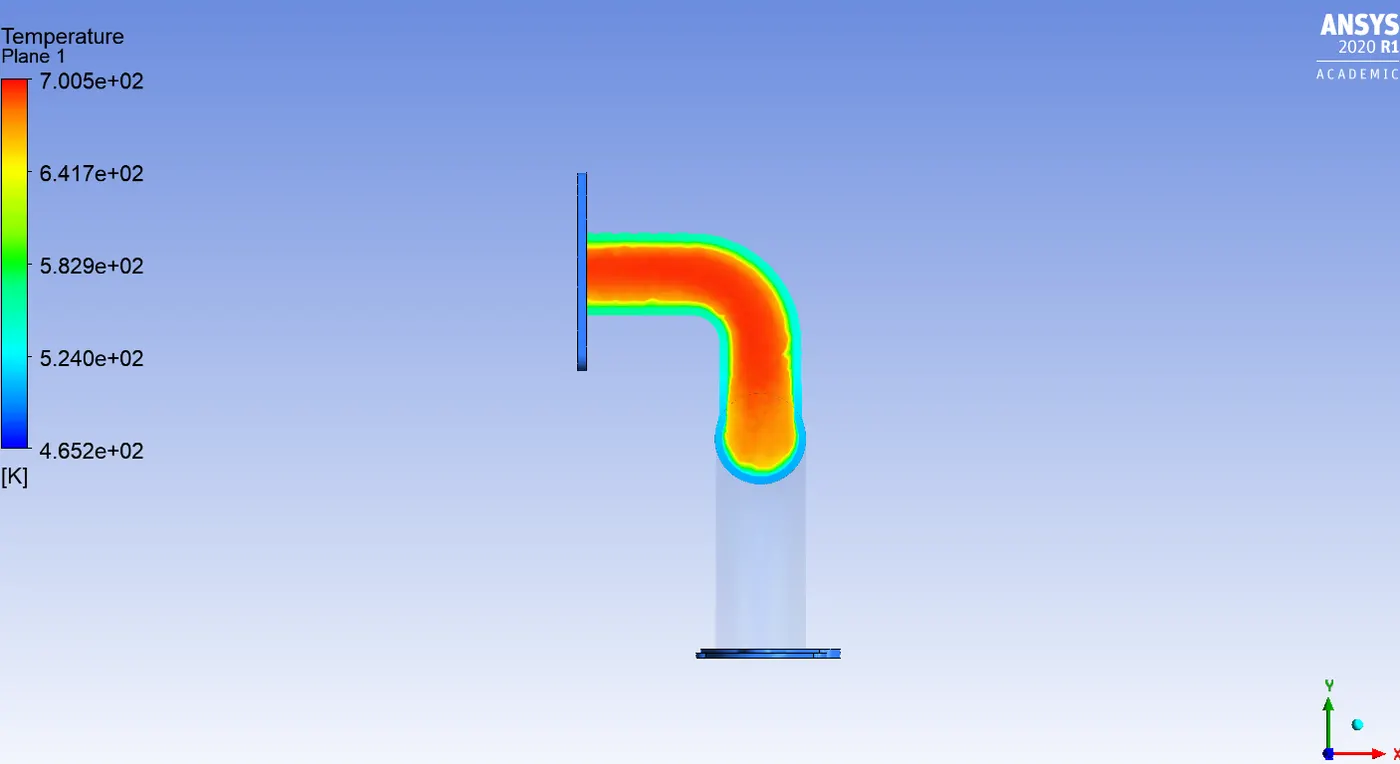
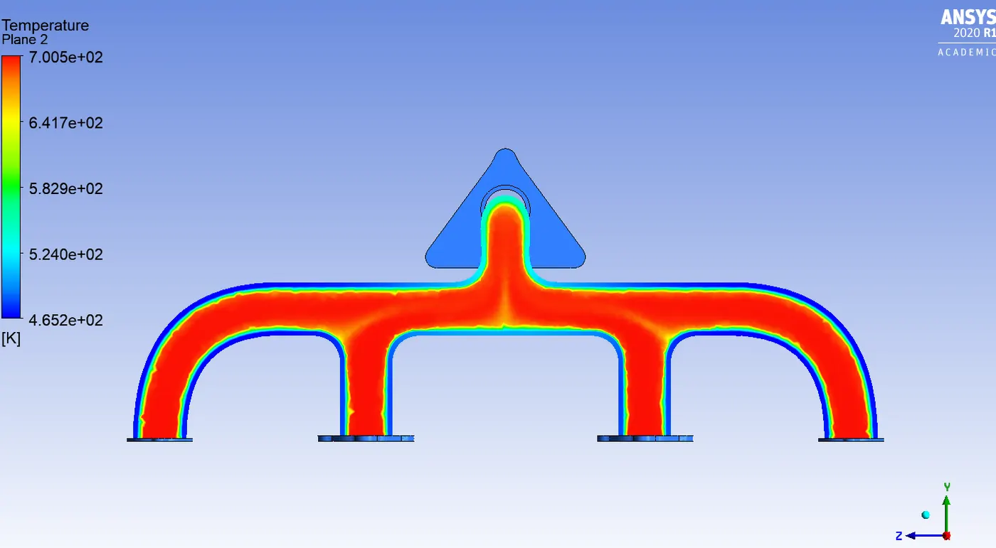
TEMPERATURE CONTOURS:
VELOCITY CONTOURS:
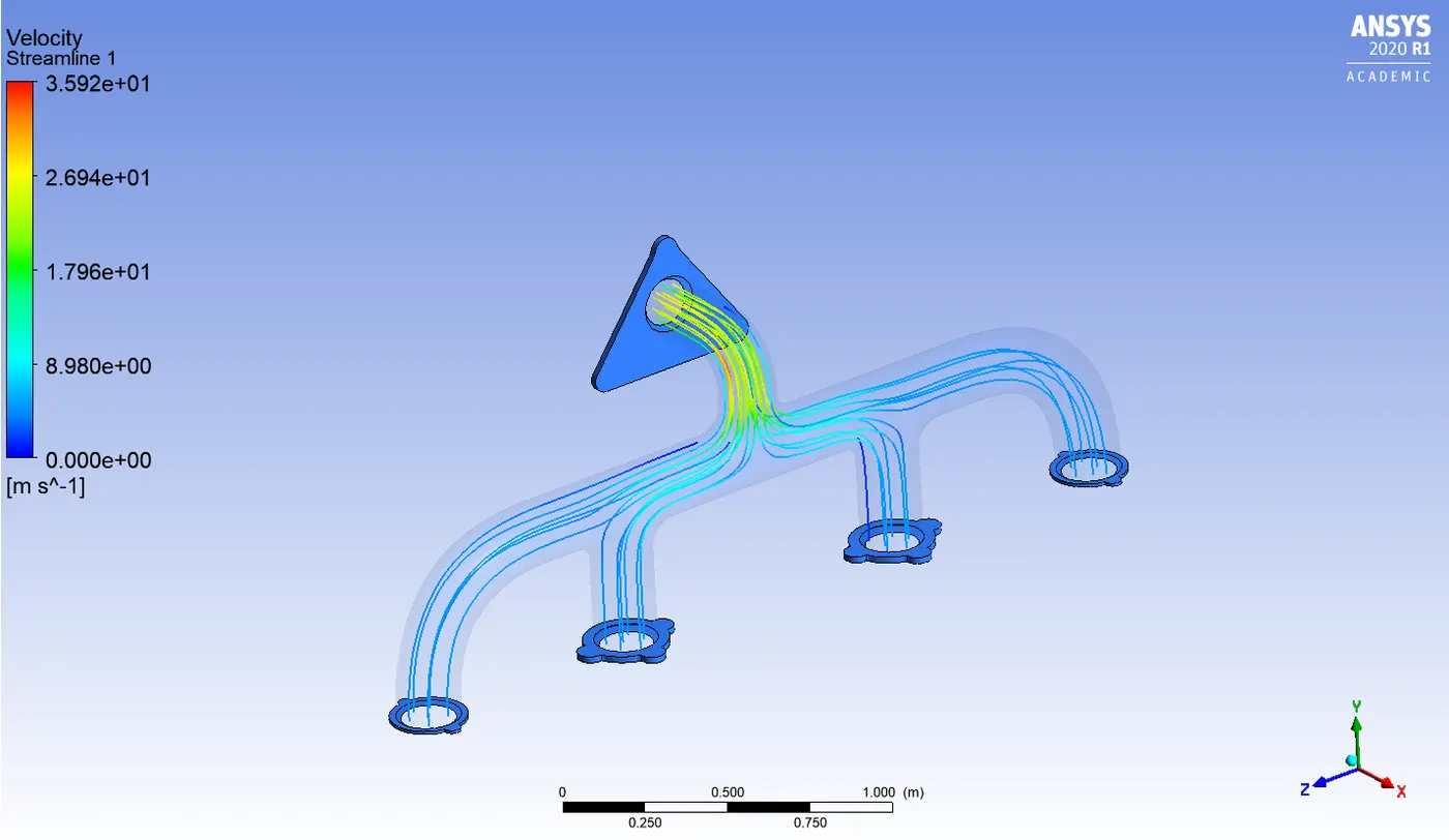
VELOCITY STREAMLINE GRAPH:
HEAT TRANSFER COEFFICIENT CONTOUR:
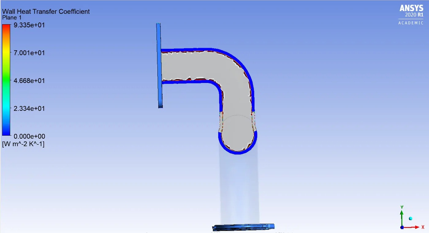
CASE 2:
REFINED MESH:
GEOMETRY:
SPACE CLAIM:
Follow the same set rules mentioned above in the case 1 setup and import the geometry in the mesh option.
MESH:
Follow the same steps as baseline mesh, give names using the named selection option.
Since this is a refined mesh case we are increasing the no.of.cells and we are giving inflation layers.
First we need to use the body sizing option in the solid volume, means increasing the no.of.elements or making the mesh finer in the solid volume.
and we should use infaltion layers to get accurate heat transfer coefficient.
INFLATION OPTION: Total thickness
MAXIMUM THICKNESS: 5e-3
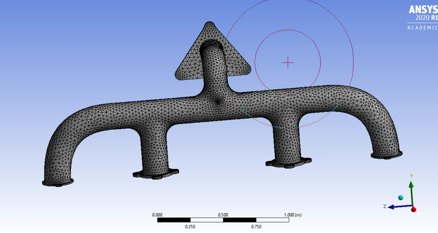
The above image represents the refined mesh
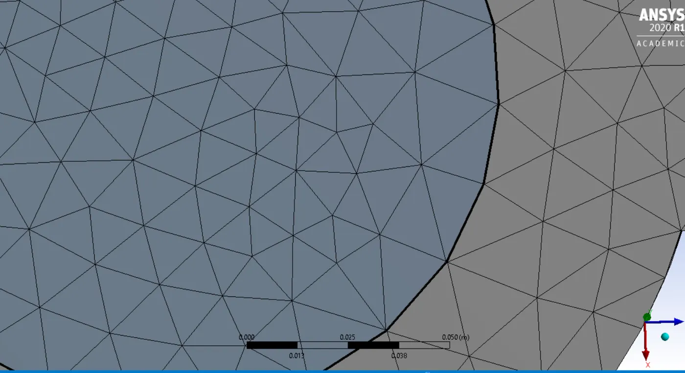
The above image represents the inflation layers
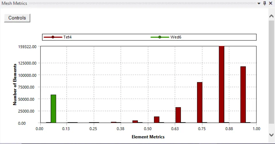
Since the mesh quality is less than 5% we can move further.
SETUP:
Follow the same set up used for the baseline mesh, Give the values as mentioned above in the boundaries.
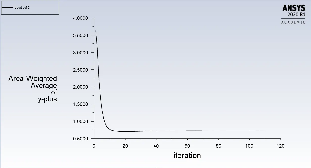
Here we use K-omega in turbulence model. Hence the Y+ value should be between 0 and 5
RESULTS:
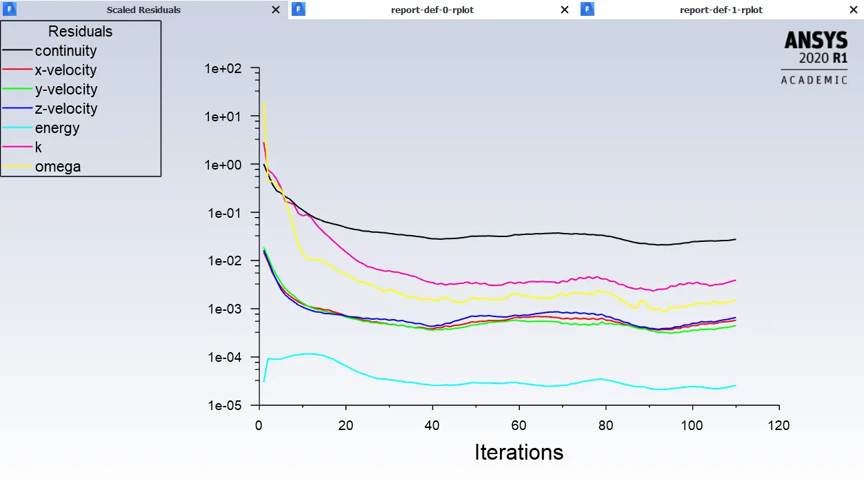
RESIDUAL GRAPH:
TEMPERATURE CONTOURS:
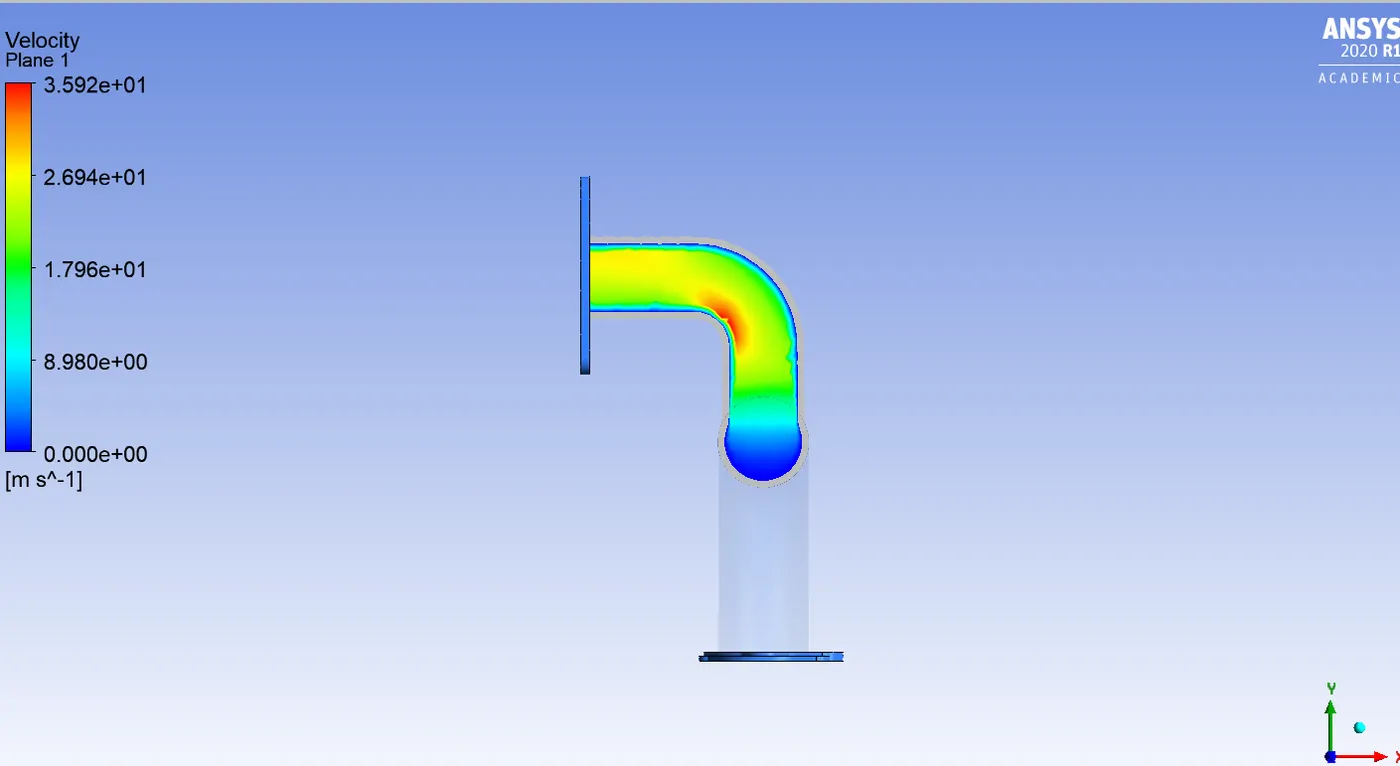
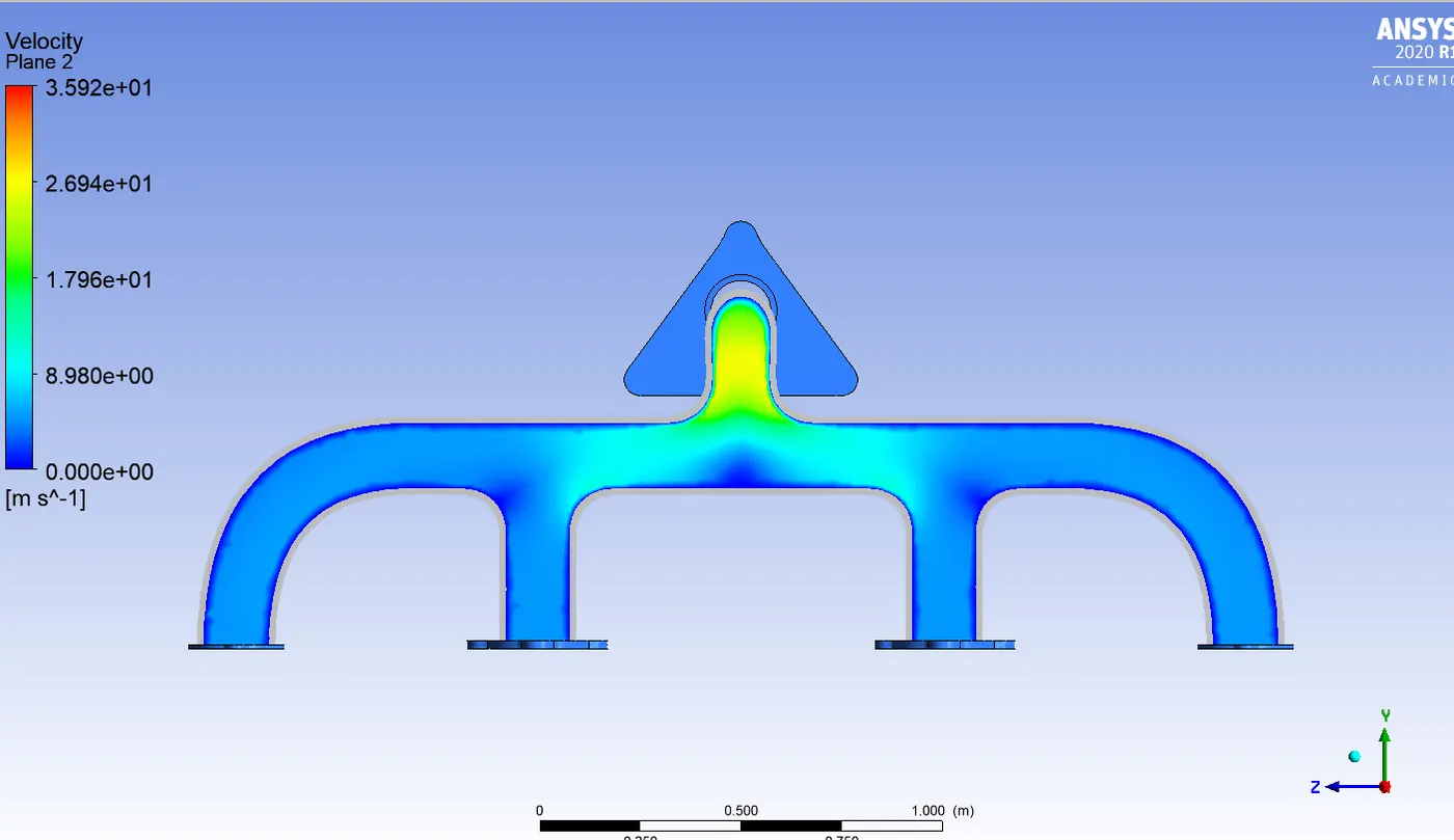
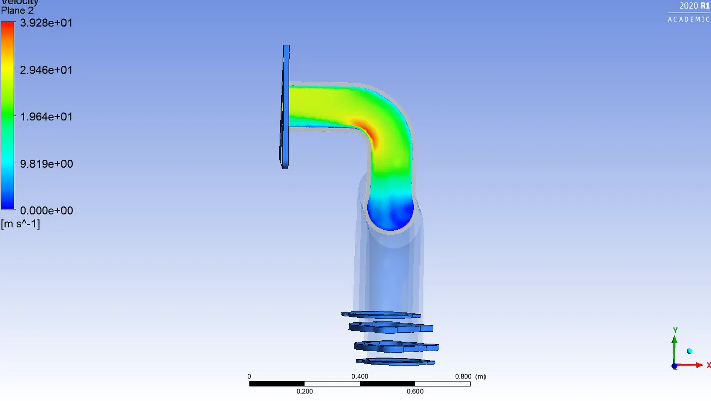
VELOCITY CONTOURS:
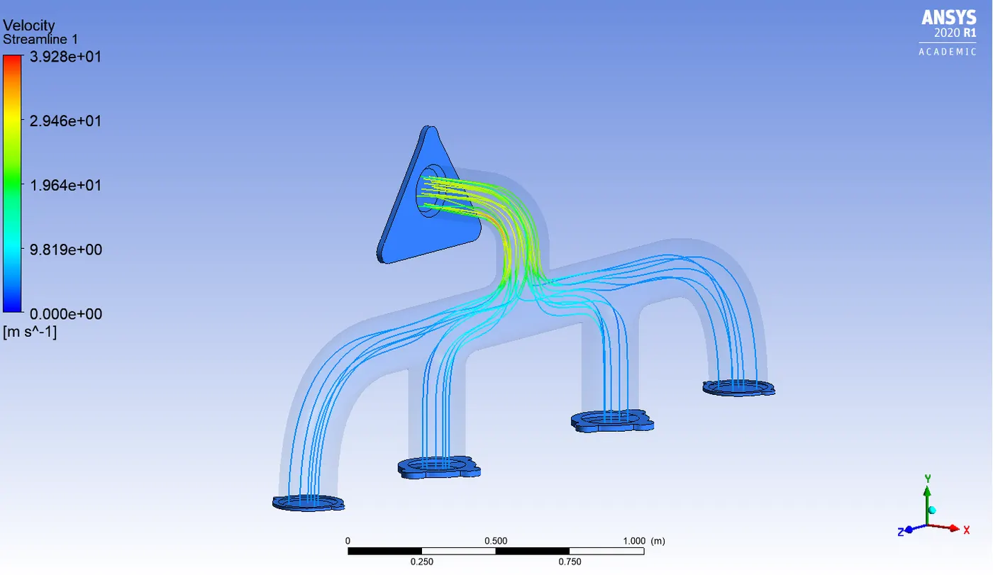
VELOCITY STREAMLINE CONTOUR:
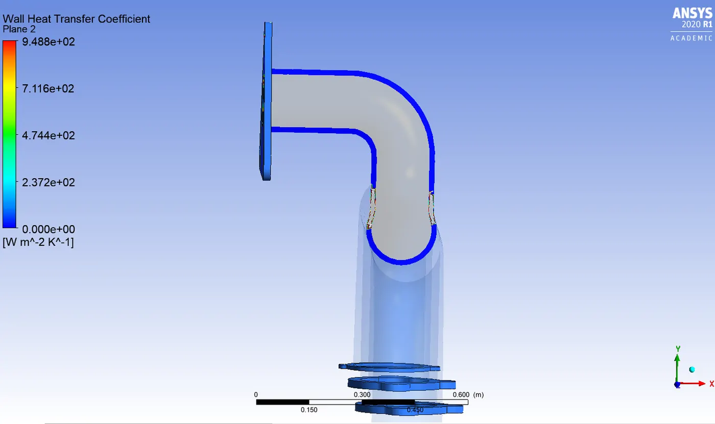
HEAT TRANSFER COEFFICIENT CONTOUR:
Y+ VALUE GRAPH
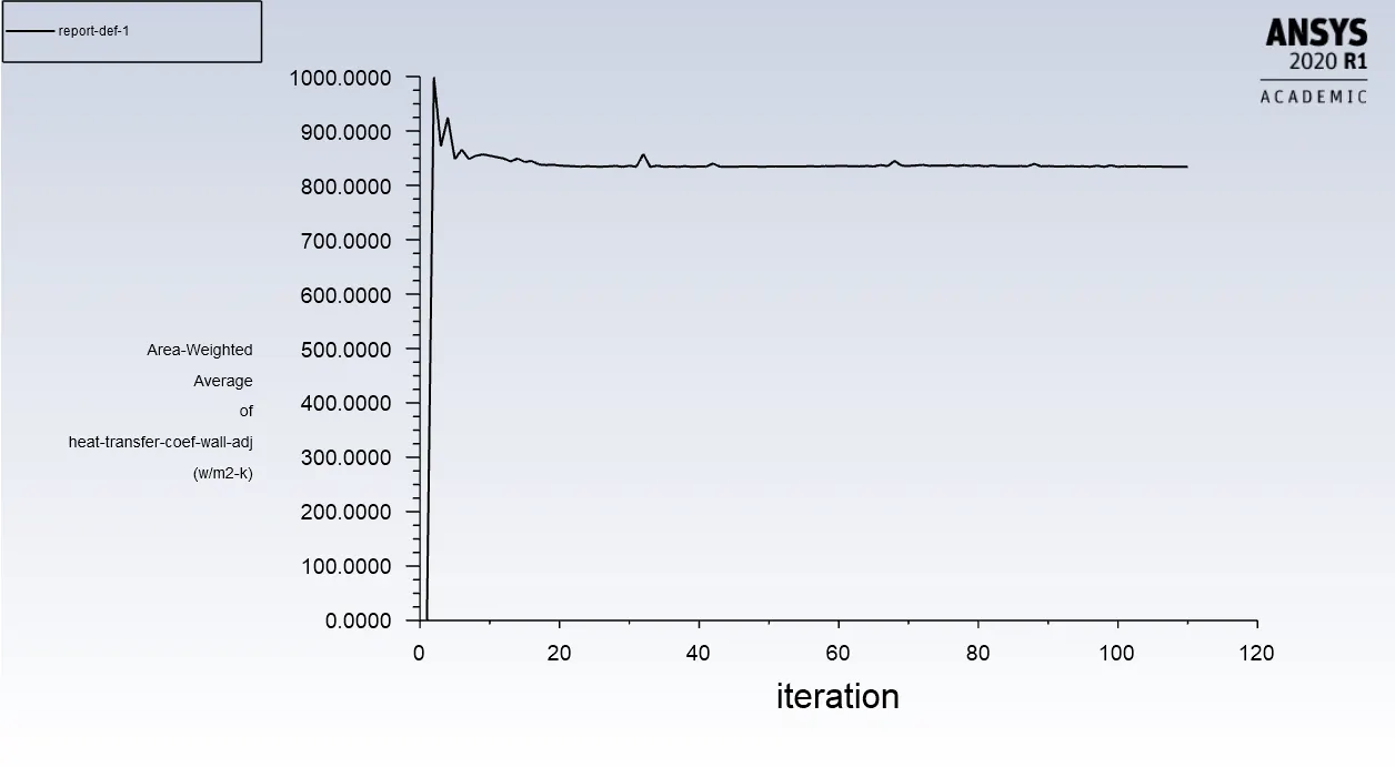
HEAT TRANSFER COEFFICIENT GRAPH:
CONCLUSION:
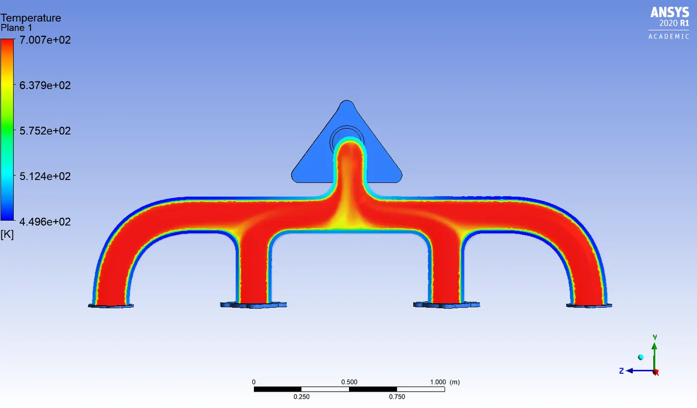
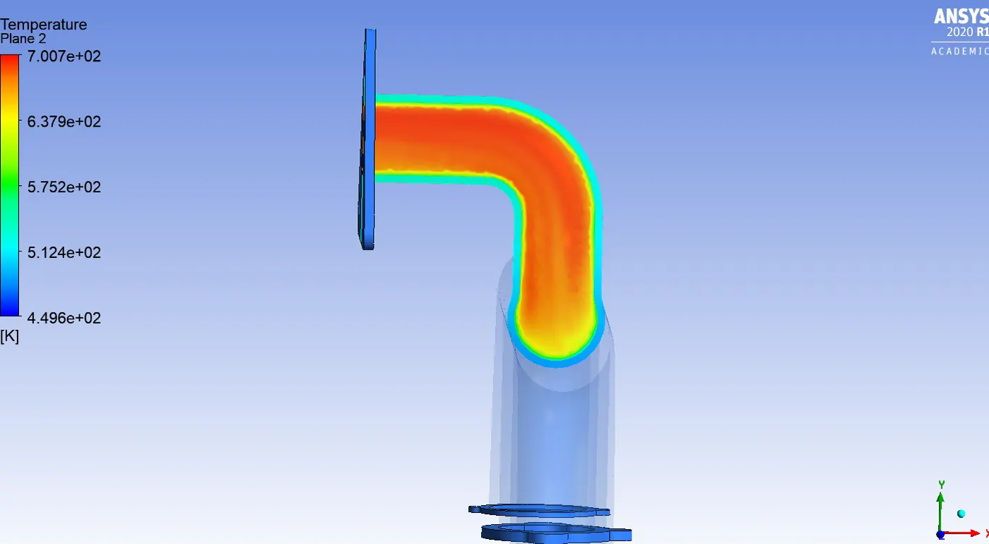
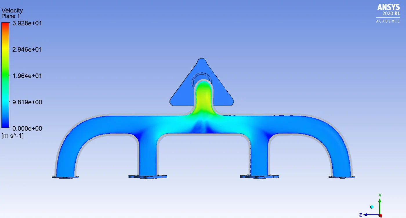
From the above two cases we can see that the results are more accurate compared to baseline mesh.We can also observe that the velocity is maximum near the bend of the pipe, This is because there are four inlets and only one outlet, So the velocity is maximum at the outlet.From the temperature contours it is clear that the temperature is low near the wall and it gradually increases and maximum near the outlet.
We also get more accurate results for the heat transfer coefficient results compared the baseline mesh this is because of the addition of inflation layers.
Some of the factors affecting the result of the solution is the element size and the need for the inflation layers. The Inflation layers are important because they give us the accurate HTC values.
VERIFICATION OF HTC PREDICTION:
NUSSELTS NUMBER:
The Nusselt number is defined as the ratio of convection heat transfer to fluid conduction heat transfer under the same conditions.
`Nu = frac{hl}{k]`
Where,
h - Heat transfer coefficient
L - Characteristic length
K - Thermal conductivity
We can also write the nusselts number formula with respect to reynolds number
`Nu = 0.023.re^frac{4}{5}.Pr^frac{2}{5}`
we know the formula for re that is
`Re = frac[rhovl}{nu}`
Here we can see that the velocity is directly propotional to the velocity, This means that if the velocity increases reynolds number also increases.
In the velocity contours you can observe that velocity is maximum at the outlets it means that the reynolds number is also high at the outlets, From the above given formula we can state that when the reynolds number increases the nusslets number increases.
Since the nusselts number is directly propotional to heat transfer coefficient, we can say that when the nusselts number increases the HTC value also increases.
By this way we can verify the heat transfer coefficient.