EV DRIVETRAIN
EV DRIVETRAIN
AIM –
- To understand different types of power converters found in EV and HEV.
- Duty ratio and power electronics on the vehicle control.
- Author's perspective of induction versus dc brushless motors by Wally Rippel, tesla.
Q.1) Which types of power converter circuits are employed in electrical and hybrid electric vehicles?
Power converters are electrical and electronic circuits that are used to either connect DC to AC and vice versa or to convert one level of DC voltage into another one (step up or step down).
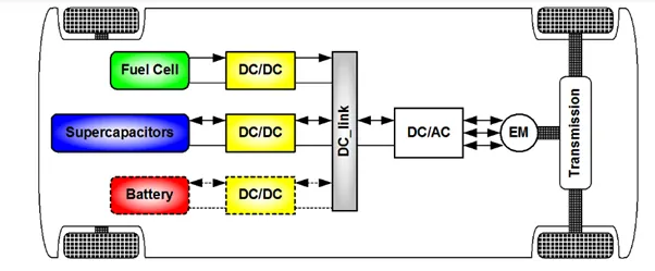
There are four different types of power converters but three power converters are employed in EV which are discussed below-
Power electronic converters are used everywhere in normal daily routines at home, commercial workplaces or in an industrial environment.
Due to high power handling capacity with higher efficiencies, these converters become integral part of industrial electrical drives, high electric power supplies, electric traction systems and automobile control equipment.
There are different types of power electronic converters used to perform different functions (for example – inversion, rectification etc.) which are rated from few mill watts to a few thousand watts.
EV / HEV Powertrain Basics –
The powertrain provides power to the vehicle. It refers to a set of components that generate required amount of power to move the vehicle.
The powertrain EV is way simpler in construction than those vehicles associated with IC Engines.
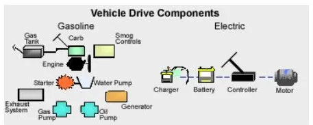
An ICE vehicle has a greater number of moving and rotating parts of which Engine, Transmission, and Driveshaft are important. Power is generated by engine and transmitted to driveshaft and this consist major electrical components along with differentials, axles, emission controls, engine cooling system, exhaust and other parts.
But EV drivetrain consists of less parts than ICE vehicle –
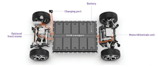
- Battery pack – this is made up of multiple lithium ion cells and stores the energy required to run the vehicle and provide direct current (DC) output.
- DC - DC Converter – A battery pack delivers fixed voltage; but the requirement of the different auxiliaries in the EV would vary. The DC –DC converter helps to step down and distribute power to different systems.
- Battery Management System – BMS continuously monitors the state of the battery and is responsible for cell balancing to deliver max. efficiency from the battery pack.
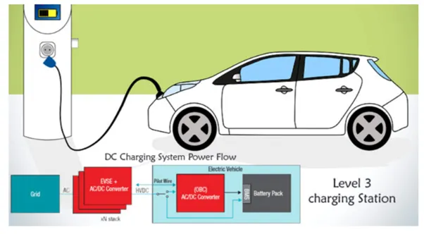
- ON – Board Charger – it converts AC received from port to DC to charge back the battery pack.
- DC – AC Converter – the DC supplied by the battery pack is converted to AC to energize electric motor. This power transfer is managed effectively by a motor.
- Controller – it controls the frequency of the voltage with the help of power electronic modules which in turn controls the magnitude of the voltage in order to manage the speed of the motor as per the acceleration of the vehicle.
- Electric motor – this is the prime of an EV unit which converts electrical energy to mechanical energy and delivers to the wheels via direct transmission or single ratio transmission. This motor can act in regeneration modes.
- CAN module – this carries communication between the control unit and the vehicle and motor.
Power electronics is the application of solid state electronics to the control and conversion of electric power.
In modern systems, the conversion is performed with semiconductor switching devices such as the power MOSFET & IGBT. In contrast the electronic systems concerned with transmission and processing of signals and data, in power electronics substantial amounts of electrical energy is processed. The power range is typically from tens of watts to several hundred watts. In industry a common application is the Variable Speed Drive that is used to control the induction motor. The power range of VSDs start from hundred watts and end at tens of megawatts.
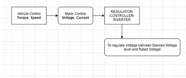
Switching Technique is adopted from power electronics to control voltage and current for electric motor for electric motor. This avoids high volume of losses by replacing resistor with power switch and these motor modules are operated with high frequency where the Rated Battery Voltage (Vbat) can be reduced to desired voltage by ON – OFF of Modules.
Switching frequency will be in such a way that it utilises Vbat and high & low switches to maintain average desired voltage.
The principle behind power modules isn’t controlling the magnitude of the voltage but the duration of high and low value of a voltage resulting the desired voltage level.
& this ON – OFF frequency is termed as Duty – Ratio.
Duty Ratio (D) = (ON time)/ (ON + OFF) time.
By changing the duty ratio of the power modules, we can vary the voltage from one level to another level.
Vavg. = Vbat * D
Introduction to Power Electronic Converters –
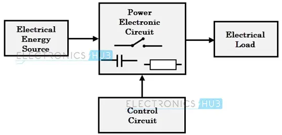
Power electronic converters uses power electronic components such as SCRs, TRIACs, IGBTs to control and convert electric power 7 the main aim of the converter is to produce power conditioning with respect to the certain application.
According to the respective functions performed, power electronic converters are categorized in the following types –
AC to DC – Rectifier, it converts AC to unipolar (DC) Current.
DC to AC – Inverter, it converts DC to AC of desired frequency and voltage.
DC to DC – Chopper, it converts constant to variable DC or variable DC to constant DC.
AC to AC – Cycloconverter, Matrix converter – it converts AC of desired frequency or desired voltage magnitude from AC supply.
These power electronic converters may be found in wide variety of applications such as switch mode power supplies (SMPS), Electric Machine control, Energy storage systems, Lightning drives, Power generation & distribution, Active power filters, Renewable energy conversion, flexible energy transmission let us go in detail about each converter –
AC to DC converters / Rectifiers –
These converts AC supply from main lines to DC supply or the load. The block diagram of this converter is shown as below –
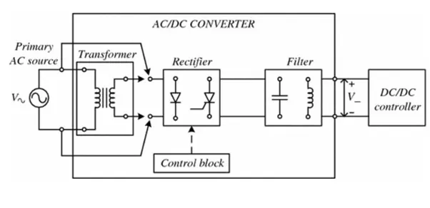
The essential components of the rectifier include Transformer, Control Block, Filter, Switching Unit.
Transformer adjusts the primary AC source supply to the input of rectifier stage. Usually it is step down transformer that reduces the supply voltage to a circuit operating range.
The rectifier converts the low voltage AC supply into DC supply. It consists of diode / thyristors based on type of rectifier, the output of the rectifier is of pulsed DC and hence it is filtered using filter circuit, which is usually made with a capacitor or a choke.
The control block controls the firing angle of thyristors in case of phased controlled rectifiers. Since the diode is not controllable device, control block is not needed in case of diode rectifiers.
Rectifiers are divided into two types -
- Uncontrolled diode rectifiers.
- Controlled rectifiers.
Inverters / DC to AC converters -
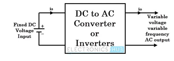
These converters are connected between DC source of fixed input and variable AC load. Most commonly these DC to AC converters are called Inverters. An inverter is a static device that converts fixed DC supply voltage to variable AC supply voltage.
Fixed DC voltage is obtained from batteries or by DC link in most power electronic converters. The output of the inverter can be variable or fixed AC voltage with variable or fixed frequency.
This conversion from DC to AC along with variable supply is produced varying the triggering angle of the thyristors. Most of the thyristors are used in inverters are employed with forced commutation technique.
This can be single phase or three phase inverter depending upon the supply voltage. These converters are mainly divided into two groups - one is PWM based inverters and other is multilevel inverters.
Further these are classified voltage source inverters and current source inverter. Each type is subdivided into different types of PWM, SVPWM etc. Multilevel inverters are most popular in industrial applications.
DC to DC converters –
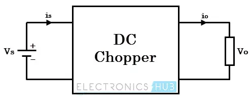
Many DC operated applications need different levels of DC voltage from a fixed DC source.
Some of these applications include subway cars, DC traction systems, control of large DC motors, battery operated vehicles, large buses, etc. which require variable DC to produce variable speed, so a power conversion device is needed.
A DC chopper is a static device that converts a fixed input DC voltage to variable DC output of different magnitude (which can be lower or higher) than input value.
The chopper circuit is connected between DC input source and DC load. The chopper consists of power electronics switching devices such as pulse with modulation (PWM) control.
DC choppers are mainly used in DC drives i.e. EVs and HEVs.
DC choppers are classified into three basic types based on input and output voltage levels and are discussed below –
Step Up Chopper or Boost Up Converter –
In this chopper the output voltage is always greater than input voltage and a switch is also used connected in parallel with the load and the switch is thyristor or a SCR.
A diode is placed in series with the load that allows load current to flow when the thyristor is turned OFF.
When thyristor is turned ON, the diode is reverse biased and hence it isolates the load circuit from the source. So the inductor charges to the maximum input voltage source.
When the thyristor is turned OFF, the load gets the voltage from the input as well as from inductor. So the voltage appearing across the converter output will be more than the input.
Step Down Chopper or Buck Converter –
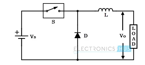
a step down chopper produces an average output voltage lower than input DC voltage. Here the switching component is a thyristor that switches the input voltage to the load when it is triggers at particular instant.
A diode acts as a freewheeling diode that allows the load current flow through it when thyristor is turned OFF. If this diode is absent, a high induced EMF in inductance may cause damage to the switching device.
The average output voltage of the converter is varied by controlling turn ON/OFF periods of thyristor. When thyristor is turned ON, the output voltage is same as the input voltage and if it is turned OFF, the output voltage is zero. And the output voltage is equal to (TON / T) Vin. So by controlling the duty ratio K = (TON /T), The output voltage will be increased.
Flyback Converter –
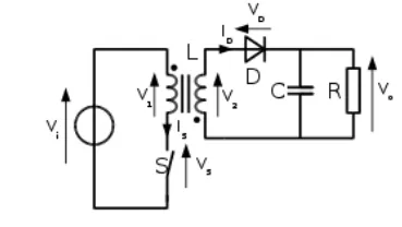
The flyback converter is used in both AC/DC & DC/DC conversion with galvanic isolation between the input and any outputs. The flyback converter is a buck – boost converter with the inductor split to form a transformer, so that the voltage ratios are multiplied with an additional advantage of isolation for example a Driving lamp or a Voltage Multiplier the rectifying diode of the boost converter is left out and the device is called a flyback transformer.
Forward Converter –
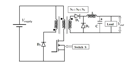
The forward converter is a DC – DC converter uses transformer to increase or decrease the output voltage and provide galvanic isolation for the load with multiple output windings and it is possible to provide low voltages and high voltages outputs simultaneously
While it looks similar as flyback converter, it operates in a fundamentally different way and is generally more energy efficient. A flyback converter stores the energy in the magnetic field in the inductor gap during the time the converter is switching the element (transistor) is conducting. When the switch turns OFF, the stored magnetic field collapses and energy is transferred to the output of the flyback converter as electric current. The flyback converter can be viewed as two inductors sharing a common core with opposite polarity windings.
In contrast the forward converter (which is based on a transformer with same polarity windings, higher magnetizing inductance and no air gap) doesn’t store the energy during the conduction time of switching element - transformers cannot store a significant amount of energy, unlike inductors instead energy is passed directly to the output of the forward converter by transformer action during switch conductance phase.
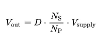
While the output of the flyback converter is theoretically infinite, the maximum output voltage of the forward converter is constrained by the transformer turns ratio Ns / Np.
AC – AC converter –
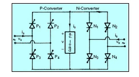
These types of power electronic converters are used to convert alternating current waveforms of specific magnitude and specific frequency into alternating current waveforms with different magnitude and different frequency, as the signal remains AC and hence this converter is termed as AC –AC converter. To operate a few devices and machines we require some specific voltage with specific frequency can be obtained with AC – AC converters and by regulating AC power using AC – AC converter we can regulate the speed of induction motors. There are different types of AC –AC converters which are classified based on different criteria.
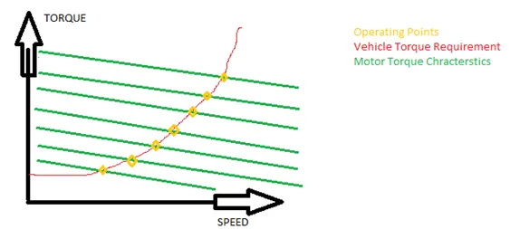
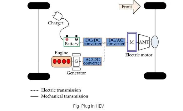
Q.2) An electric vehicle drivetrain with 72 V battery pack is shown in the diagram below. The duty ratio for acceleration operation is “D1” and for the braking operation the duty ratio is “D2”, What is EV steady state speed if duty cycle is 70%?
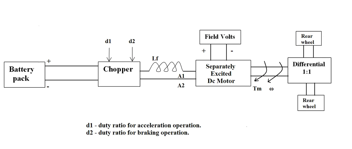
>> given –
Rated Armature Voltage = 72 V.
Rated Armature current = 400 A.
Ra = 0.5 `Omega`.
K`phi` = 0.7 V–s.
Chopper switching frequency = 400Hz.
The vehicle characteristics are given by equation –
Tm = 24.7 + 0.0051 `omega`2. ……… (1)
it is given that the duty cycle is 70% so the average voltage is Vo = [72*(700 / 100)] = 50.40 V.
we know the DC motor torque speed equation is given by: -
Tm = [Vo * K`phi` – {W * (K`phi`)2 / Ra}]………….(2)
Putting all the values in equation 2 we get,
Tm = [(50.40 * 0.7 / 0.5] – {`omega` * 0.72 / 0.5}]
Tm = 70.56 – 0.98 `omega` …………. (3)
Now we have two equations, equating equations (2) & (3) we get,
Tm = 24.7 + 0.0051`omega`2 = 70.56 – 0.98W
0.0051 `omega`2 + 0.98 W – 45.86 = 0
Using Shreedhar Acharya’s formula we get

Solving this equation we get two different values of omega that is
`omega` = 39.92 Rad / Sec.
`omega` = 231.08 Rad / Sec.
Omega with positive sign is for the forward direction so we will take only `omega` = 38.92 Rad / Sec. for steady state speed.
Q.3) Study the blog on Induction vs. DC brushless motors by Wally Ripple, Tesla & explain in brief about the author’s perspective.
Wally Ripple is a long-time proponent of electric vehicles. Prior to joining Tesla Motors, he was an engineer at Aeroviornment, where he helped to develop the Ev1 for GENERAL MOTORS.
He was featured in the documentary movie – Who killed the Electric Car? Wally has also worked for the Jet Propulsion Laboratory on electric vehicle battery research, among other projects.
In 1968 as a Caltech Undergraduate student, he built an electric car (A converted 1958 Volkswagen Microbus) and won the great Transcontinental electric car race against MIT.
He has written a blog on Induction Motor Vs. DC Brushless Motors by comparing all its strengths and weaknesses.
Geometry & Principle –
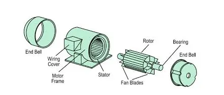
AC Induction Motor.
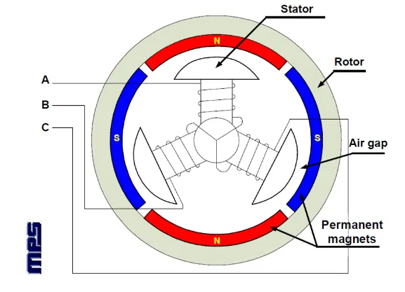
Brushless DC Motor
In brushless machines, the rotor has 2 or more permanent Magnets which will generate a DC magnetic field and in turn, this magnetic field enters the stator core and interacts with currents flowing within windings to produce torque interaction between the rotor and stator.
The stators for the 3 phase induction motor & DC brushless motor are virtually identical. Both have three sets of “Distributed Windings” that are inserted within stator core and the essential difference between the two machines is the Rotor.
As the rotor rotates, it is necessary that the magnitude and polarity of the stator currents be continuously varied and in just the right way such that the torque remains constant and the conversion of electrical and mechanical energy is optimally efficient. The device that provides the current control is called an inverter. Without it, the brushless motors are useless.
Unlike DC brushless rotors, the induction rotor has no magnets – just stacked steel laminations with buried peripheral conductors that form a ‘Shorted Structure’. Currents flowing in the stator windings produce a rotating magnetic field that enters the rotor. In turn the frequency of this magnetic field as ‘seen’ by the rotor is equal to the difference between he applied electrical frequency and the “Rotation Frequency” of the rotor.
An induced voltage exists across the shorted structure and that is proportionate to this speed difference between the rotor and electrical frequency. In response to this voltage current are produced within the rotor conductors that are approximately proportionate to the voltage, hence the speed difference. Finally, these currents interact with the original magnetic field to produce forces – a component of which is the desired rotor torque.
The significant difference in the geometry is the rotor and the principle of inverter control.
Brushless machine requires position sensors whereas the induction machine requires the speed sensors.
Brushless / Induction –
The induction machines are capable to start under load and they require an inverter.
In contrast, a brushless DC motor produces no starting torque when directly connected to fixed frequency utility power. They really need the aid of an inverter whose “Phase” is maintained in step with the angular position of the rotor.
Induction machines cannot operate from DC; AC is must and shaft speed is proportionate to line frequency.
IMs have limited starting torque and somewhat limited running peak torque capabilities when compared to DC type machines
Adding an inverter makes it possible to power an induction machine from a battery or other DC source; variable speed also becomes possible simply by adjusting the inverter frequency.
Torque performance of IMs are low as compared to DC machines.
Add some feedback loops to IMs such that the inverter produces the exact frequency that the motor desires and the induction motor is capable of competing with DC and DC brushless for vehicle applications.
DC brushless drives require an absolute position sensor, while induction drives require only a speed sensor and these difference are relatively small.
One of the main differences is that much less rotor heat is generated with the DC brushless drive. Rotor cooling is easier and peak point efficiency is generally higher for this drive.
The DC brushless drive also can operate at a unity power factor, whereas the best power factor for the induction drive is about 85 percent. Therefore, the peak point energy efficiency for a DC brushless drive will typically be a few percentage points higher than for an induction drive.
The DC brushless drive can also operate at unity power factor, whereas the best power factor for the induction drive is about 85 percent this means that the peak point energy efficiency for the DC brushless drive will typically be few percentage points higher than for an induction drive.
N an ideal brushless drive the strength of the magnetic field produced by permanent magnets would be adjustable. When maximum torque is required especially at low speeds, the magnetic field strength (B) should be maximum so that the inverter and motor currents are maintained at lowest possible values & this minimizes the I2 R (Current2 Resistance) losses and thereby optimizes efficiency. Likewise, when torque levels are low, the B field should be reduced such that eddy and hysteresis losses due to B are also reduced, ideally B should be such that the sum of eddy, hysteresis and current2 losses are minimized. Unfortunately, there is no easy way of changing B with permanent magnets.
In contrast the induction machines have no magnets and “B” fields are adjustable since B is proportionate to V /f (Voltage to Frequency). This means that at light loads the inverter can reduce voltage such that magnetic losses are reduced and efficiency is maximized. Thus, the induction machine when operated with smart inverter has an advantage over DC brushless machine – Magnetic and conduction losses can be traded such that efficiency is optimized.
With DC brushless, as machine size grows, the magnetic losses increase proportionately and part load efficiency drops and with induction as machine size grows, losses don’t necessarily grow thus the induction drive may be favoured approach where high performance is desired; peak efficiency will be little less than DC brushless but average efficiency may be actually better.
Cost effectiveness –
Permanent magnets are expensive something like $ 50 / kilogram and these rotors are also difficult to handle due to large forces that come into play when anything ferromagnetic gets close to them. This means that induction motors will likely to retain a cost advantage over PM machines and also due to field weakening capabilities of induction machines inverter ratings and costs appear to be lower especially for high performance drives since spinning induction machines produces little or no voltage when de-excited and they are easier to protect.
Induction machines are more difficult to control. the control laws are more complex and difficult to understand. Achieving stability over entire torque speed range and over temperature is more difficult with induction than brushless DC motor. This means added development costs but little or no recurring costs.
Conclusion –
- From author’s point of view, it is clear that ‘There is no one best engine type, rather there are different types of engines to suit personal requirements’ such as price and performance and this is also true for electric vehicle drives.
- While developing hybrid or pure electric vehicle we need high performance and low developing cost we need to select induction motor.
- In future hybrid electric vehicles also will be developed to wrap a lot of performance characteristics like pure EVs and hence author concludes with the vision stating ‘we will see induction and DC brushless working together at the same time in the coming golden era of hybrid and electric vehicles’