DUTY CYCLE & POWER ELECTRONICS
DUTY CYCLE
AIM:
- To study on the Efficiency & Losses occurring in Power Electronics circuit.
- To generate Duty Cycle control signal from a simple Power converter circuit in MATLAB.
- Comparison of Square wave Inverter with Sine modulated wave Inverter.
- To study the difference between VFD & Vector Control drive.
-------------------------------------------------------------------------------------------------------------------------------
- Power Electronics Circuit – Efficiency & Losses
Power Electronics
Power electronics is the application of solid-state electronics to the control and conversion of electric power.
In modern systems, the conversion is performed with semiconductor switching devices such as diodes, thyristors, and power transistors such as the power MOSFET and IGBT. In contrast to electronic systems concerned with transmission and processing of signals and data, in power electronics substantial amounts of electrical energy are processed. The power range is typically from tens of watts to several hundred watts. In industry a common application is the variable speed drive (VSD) that is used to control an induction motor. The power range of VSDs start from a few hundred watts and end at tens of megawatts.
Switching Technique is adopted from Power Electronics to control the Voltage and Current for Electric Motor. This avoids high amount of losses by replacing Resistor with and Power Module/Switch. And these Power Modules are operated at high Frequency where the Rated Battery Voltage (Vbat) can be reduced to desired voltage by ON-OFF of Modules.
Switching Frequency will be in such a way that it utilizes Vbat & switches low and High to maintain Average desired Voltage.
The principle behind the Power Modules is not controlling the Magnitude of the Voltage but the duration of High & Low Value of Voltage resulting the desired Voltage level.
This ON-OFF Switching Frequency is referred in terms of Duty Ratio
Duty Ratio (d) = (ON) time/(ON+OFF) time
By changing the Duty Ratio of the Power Modules, we can vary the Voltage from one level to another level.
Vavg = Vbat * d
Power Modules/Switches
When it comes to EV application, controlling the Speed of the Motor mainly depends on controlling the Voltage & Current flowing to the Motor. To ensure a rotating field in the motor continuously, flux has to be switched continuously by controlling the direction and timing of the Current in to the coil.
In order to achieve this Controllers/Inverters are used to adjust the Voltage in the coil and to control the magnitude of current.
PWM (Pulse Width Modulation) is the technique incorporated in Power switches which alters the Voltage level by lengthening or reducing the Pulse ON time.
Efficiency of the Power Electronic Circuit
Power electronics deals with the conversion and control of electrical energy with the help of power semiconductor devices that operate in a switching mode, and, therefore, efficiency of power electronic apparatus may approach as high as 98–99%.
Since these devices have no mechanical moving parts, there are very less failure chances and hence has a very rugged performance and long life, provided it is operated under rated conditions and hence they are highly reliable.
In most of the applications these devices act as a switch and we know that in both the modes of the switch, i.e. ON and OFF the power loss in it is very less, and the switching losses are also very low. Hence, they are highly efficient.
Losses in Power Electronic Circuit
Power semiconductors are thermally limited and a good thermal design is the key to their cost-effective utilization. Thermal design is important in all applications but is particularly important for power semiconductors for two reasons:
- They operate with very large current densities and with a steep temperature gradient between junction and ambient.
- The thermal mass of a semiconductor is very small and it can go into a thermal runaway in a fraction of a millisecond.
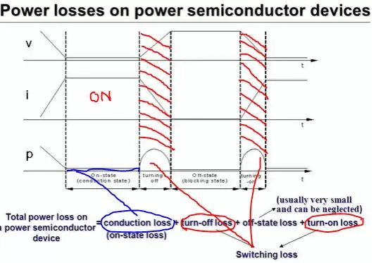
There are 2 main losses in the power dissipation of the circuits,
- Switching Losses occur when the device is transitioning from the blocking state to the conducting state and vice-versa. This interval is characterized by a significant voltage across its terminals and a significant current through it. The energy dissipated in each transition needs to be multiplied by the frequency to obtain the switching losses.
- Conduction Losses occur when the device is in full conduction. The current in the device is whatever is required by the circuit and the voltage at its terminals is the voltage drop due to the device itself. These losses are in direct relationship with the duty cycle.
-------------------------------------------------------------------------------------------------------------------------------
- To generate Duty Cycle control signal from a simple Power converter circuit in MATLAB.
Let us consider available power_Hbridge model to simulate for the duty cycle control signal
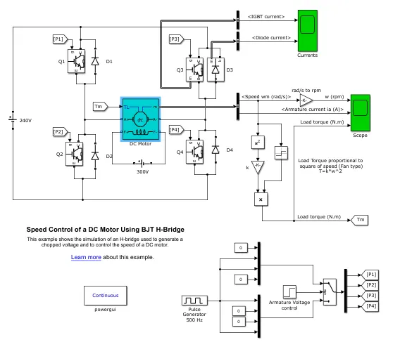
This example shows the simulation of an H-bridge used to generate a chopped voltage and to control the speed of a DC motor.
Source: https://in.mathworks.com/help/physmod/sps/examples/speed-control-of-a-dc-motor-using-bjt-h-bridge.
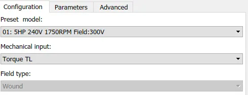
Pre-set Configuration
Duty Cycle/Pulse Generator Block
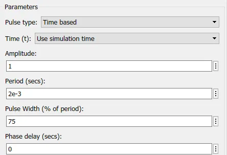
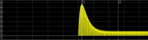
With a Duty Cycle ratio of 0.75, initial Peak current of 66A is drawn and continuous current of 10A is available for Motor.
Now, on changing the duty cycle to 0.85
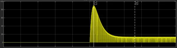
Initial Peak current of 88A is drawn and continuous current of 13A is available for Motor.
It can be observed that, with increase in the Duty cycle ratio, Pulse width will be modified which results in the increase in the Supply Voltage and hence the Motor Current.
-----------------------------------------------------------------------------------------------------------------------------
- Comparison of Square wave Inverter with Sine modulated wave Inverter.
The inverter converts battery DC electricity to AC electricity. DC signal looks like a unidirectional straight line and AC signal looks like waves of ocean. But the battery stores the power as DC, the inverter converts this DC current to somewhat similar to AC current. Depending on the inverter circuit, either inverter converts the DC current to Sine wave AC current or Square wave AC current.
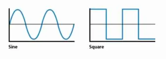
Sine wave inverter output is very close to the AC current. It is very pure form compared to Square wave output. Many devices get heated up if you use on Square wave inverter and make humming noise too.
Sine wave inverters are more efficient than square wave inverters, when it comes to the conversion of DC to AC. This ensures that the power loss is minimised, due to greater efficiency.
- A sine wave minimises the risk of damage to System. Compared to a square wave, there is very little harmonic distortion in a sine wave—essential for expensive equipment.
- Devices that use control circuits, which sense the phase for speed/voltage control, or devices that sense instantaneous zero voltage crossing (for timing control) must have a sine wave supply.
Modified Sine Wave
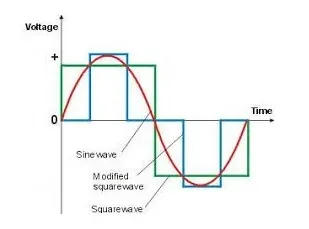
The “modified sine wave” is not really a sine wave at all. It achieves voltage regulation by varying in width according to the battery voltage and the load. Thus, the wave is not as smooth as a sine wave. The quality of “mod sine” inverters should not be underestimated, however. They are highly capable, and (by narrowing the waveform) they save energy when running only small loads, as happens during most of the day in a typical home. They also cost half the price of sine wave inverters!
-------------------------------------------------------------------------------------------------------------------------------
- To study the difference between VFD & Vector Control drive.
A Variable Frequency Drive (VFD) is a type of motor controller that drives an electric motor by varying the frequency and voltage supplied to the electric motor. Other names for a VFD are variable speed drive, adjustable speed drive, adjustable frequency drive, AC drive, Microdrive, and inverter.
Frequency (or hertz) is directly related to the motor’s speed (RPMs). In other words, the faster the frequency, the faster the RPMs go. If an application does not require an electric motor to run at full speed, the VFD can be used to ramp down the frequency and voltage to meet the requirements of the electric motor’s load. As the application’s motor speed requirements change, the VFD can simply turn up or down the motor speed to meet the speed requirement.
The first stage of a Variable Frequency AC Drive, or VFD, is the Converter. The converter is comprised of six diodes, they allow current to flow in only one direction; the direction shown by the arrow in the diode symbol. For example, whenever A-phase voltage is more positive than B or C phase voltages, then that diode will open and allow current to flow. When B-phase becomes more positive than A-phase, then the B-phase diode will open and the A-phase diode will close. The same is true for the 3 diodes on the negative side of the bus. Thus, we get six current “pulses” as each diode opens and closes. This is called a “six-pulse VFD”, which is the standard configuration for current Variable Frequency Drives.
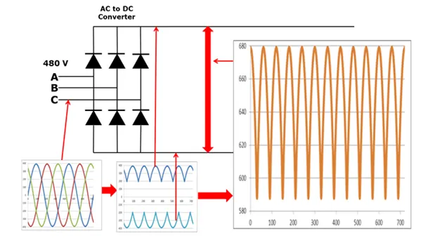
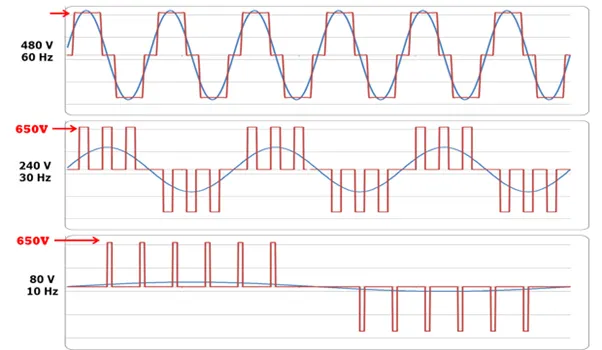
The output from the VFD is a “rectangular” wave form. VFD’s do not produce a sinusoidal output. This rectangular waveform would not be a good choice for a general-purpose distribution system, but is perfectly adequate for a motor.
If we want to reduce the motor frequency to 30 Hz, then we simply switch the inverter output transistors more slowly. But, if we reduce the frequency to 30Hz, then we must also reduce the voltage to 240V in order to maintain the V/Hz ratio. This is called Pulse Width Modulation or PWM.
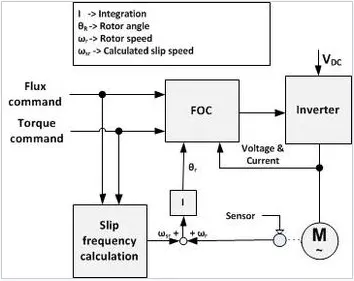
Vector control, also called field-oriented control (FOC), is a control method in which the stator currents of a three-phase AC electric motor are identified as two orthogonal components that can be visualized with a vector. One component defines the magnetic flux of the motor, the other the torque. The control system of the drive calculates the corresponding current component references from the flux and torque references given by the drive's speed control. Typically, proportional-integral (PI) controllers are used to keep the measured current components at their reference values. FOC is used to control AC synchronous and induction motors.[2] It was originally developed for high-performance motor applications that are required to operate smoothly over the full speed range, generate full torque at zero speed, and have high dynamic performance including fast acceleration and deceleration.
Can we use VFD method for induction motor in EV application?
VFD can be implemented in EV application due in large part to an increased focus on energy savings, the use of pulse width modulated (PWM) variable frequency drives (VFDs) to control AC motors, while they offer low operating costs and high performance, VFDs are not without their problems.
VFD method is so scalar that coupled flux and current cannot be differentiated in the mode of control which results in the reduction of overall efficiency of the system.
**************************************************************************************************************************************************************************************