DUTY CYCLE & CONTROL SIGNAL GENERATED FOR A BOOST POWER CONVERTER CIRCUIT.
DUTY CYCLE & CONTROL SIGNAL GENERATED FOR A BOOST POWER CONVERTER CIRCUIT.
- WHY POWER ELECTRONIC CIRCUITS ARE EFFICIENT? IN PRACTICE, WHICH TYPES OF LOSSES OCCUR IN POWER ELECTRONIC CIRCUIT?
Power electronics is he application of solid state electronics for control & conversion of electric power. The first high power electronic devices were mercury – arc valves. In modern systems, the conversion is performed with Semi-Conductor switching devices such as diodes, Thyristor, & power transistors such as Power MOSFET & IGBT. In contrast to electronic systems concerned with transmission & processing of signals & data, in power electronics substantial amounts of electrical energy are processed. An AC/DC Converter or Rectifiers the most typical power electronics device found in many consumer electronic devices, e.g. Television Sets, Personal Computers, Battery Chargers, etc. The Power Range is typically from tens of watts to several hundred watts. In industry a common application is the Variable Speed Drive (VSD) that is used to control induction motor. The power range f VSDs start from few hundred watts and end at tens of megawatts.
As the Power Electronics deals with the conversion & control of electrical energy with the help of power semiconductor devices that operate in a switching mode, and, therefore, the efficiency of power electronic apparatus may approach as high as 98-99%. power electronics is the study of switching electronic circuits in order to control the flow of electrical energy, its generation, Transportation, and applications. Power electronics is the technology behind switching power supplies, power converters, power inverters, motor drives, and motor soft corners.
N power electronics all devices operate in a switching mode – either ‘FULLY ON’ / ‘FULLY OFF’ states. For example, a BJT (Bipolar Junction Transistor) has 3 regions of operation in its output characteristics CUT-OFF, active & Saturation, in analog electronics where the BJT is supposed to work as an amplifier, the circuit is so designed to bias it inactive region of operation. However, In Power Electronics, BJT will work in cut-off region when it is OFF and in the saturation region when it is ON.
Advantages of Power Electronic System-
- High efficiency due to low loss in power semiconductor devices.
- High reliability of power electronics converter system.
- Long life & Less maintenance due to absence of any moving parts.
- Flexibility in operation.
- Fast dynamic response compared to electromechanical converter system.
- Mall size & less weight, thus low installation cost.
Types of Power Electronics Circuits –
- Diode
- AC-DC Converters. (Controlled Rectifiers)
- AC–AC Converters. (AC Voltage Converts)
- DC-DC Converters. (DC Choppers)
- DC-AC Converters. (Inverters)
- Static Switches.
- Diode Rectifiers –
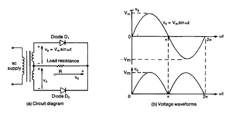
It converts AC Voltage into a fixed DC Voltage.
- AC – DC Converters –
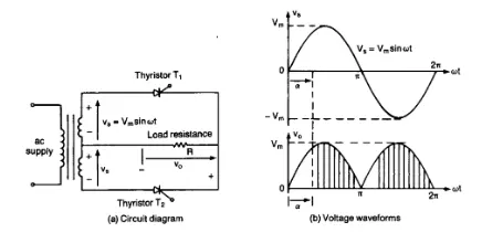
A single – Phase converter with 2 natural commutated thyristor is shown.
Average value of the output voltage can be controlled by varying the conduction time of thyristor.
These converters are also known as controlled rectifiers.
- AC-AC Converters –
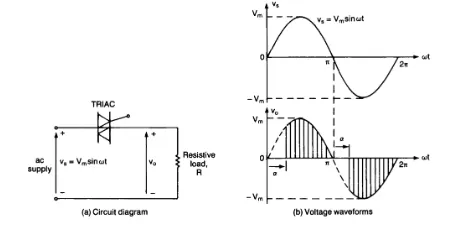
Used to obtain variable AC output voltage.
A single-Phase converter with TRIAC is shown.
- DC-DC Converter -
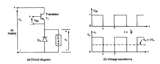
It is also known as chopper or switching regulator.
The average output voltage is controlled by varying the conduction of transistor, t1.
If T is chopping period, then t1 + T and Delta is called as Duty Cycle of Chopper.
- DC-AC Converter-
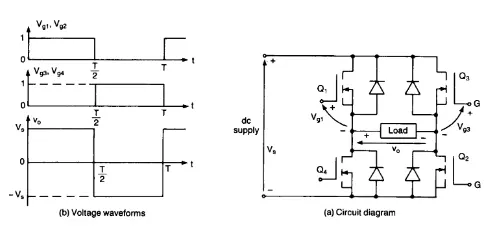
It is also known as Inverter.
If Transistor Q1 & Q2 conduct for 1½ period & Q4& Q3 conduct the other half, the output voltage is of alternating form.
- Static Switches –
Power Devices can be operated as Static Switches or Contactors, the supply to these switches could be either AC/DC and the switches are called as AC Static Switches/ DC Switches.
Power Electronics for Efficiency –
Power electronics deals with conversion and control of electrical energy with the help of power semiconductor devices that operate in a switching mode, and, therefore, efficiency of power electronic apparatus may approach as high as 98-99%. This technology uses electronic components such as inverters and transformers to convert the electricity from the wall outlet into the right voltage and current to power each of handy or handheld devices. It is also used more widely to distribute the electricity throughout the powergrid to connect renewable energy systems and to charge up the electrical vehicles, electrical energy has already become our lifeline so we want to get regulated form of this energy which in itself is not usable until it is converted into the tangible form of energy such as motion, light, sound, heat, etc. in order to regulate these forms of energy then, regulate the electrical energy itself and this forms the content of the subject power electronics. Power electronics is the study of switching of electronic circuits in order to control flow of electrical energy, its generation, Transportation and Applications. Power Electronics is the Technology behind switching Power Supplies, Power Converters, Power Inverters, Motor Drives, & Motor Soft Starters. Power Electronics is the enabling technology, its development, together with internal developments, such as wide bandgap semiconductors, will be driven externally by applications in the future.
Power electronics is very important in modern high efficiency energy processing systems such as HVDC, SVC, Flexible AC Transmission System (FACTS) for active & reactive power flow control, Uninterruptible Power Supply (UPS) AND Industrial Process Control with Variable Frequency Drives (VFDs) for improving productivity and quality of products in modern automated factories. VFDs are now used extensively in Pumps and Compressor drives, Paper & Textile Mill Drives, Subway & Locomotive Propulsion, Electric & Hybrid Electric Vehicles, Elevators, Metal Rolling, Home Appliances, Metal Tools, Variable Speed Air Conditioners, Wind Generation Systems, Ship Propulsion. Power electronics plays very important role in solving and mitigating Global Warming Problem which is serious concern in our society.
Advantages of Power Electronics –
- High Reliability of Power Electronic Converter System.
- Long life and less maintenance due to absence of any moving parts.
- Flexibility in operation.
- Fast dynamic response compared to electromechanical converter system.
- Small size and less weight and hence low installation cost.
Losses in Power Electronics Circuits –
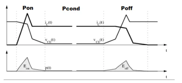
In above figure, this shows losses occur in switches during ON & OFF. Conduction Losses mainly depend on the duty cycle, Load Current and Junction Temperature, whereas switching losses depend on the load current, DC link voltage, Junction Temperature & Switching Frequency, if switching frequency is high losses will be higher.
- Conduction Losses –

Conduction Losses are those voltage and current products that occur when a power switch or rectifier is a conducting current. The duty cycle dependent.
These are the losses that occur while the IGBT or Freewheeling Diode is ON & the total power dissipation during conduction Current is computed by multiplying the ON state Voltage (Vce_sat) and the ON state current (Ic). In PWM applications the conduction losses multiplied by the duty factor to obtain average power dissipation of a 1st order approximation of a conduction losses obtained by multiplying IGBT’s Rated (Vce_sat) by the expected average device current conduction loss. The average power dissipated by the IGBT is given below –

- Switching Losses –
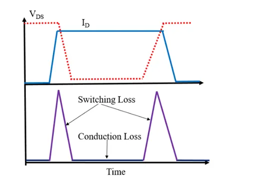
In power Electronics switching losses typically contribute significant amount to the total system losses occurred because the transitions from ON state to OFF state & Vice-Versa don’t occur during the transition interval both the current through and voltage across are substantially larger than 0 which leads to large instantaneous power loss. The curves show the simplified current and voltage waveforms and dissipated power during one switching cycle of an IGBT in an inverter. For e.g. if one plans to calculate junction temperature time behaviour to improve reliability of the design, it is necessary to calculate accurately the switching losses.

- Using a suitable MATLAB model, show how duty cycle control signal can be generated foe a simple power converter circuit?
What is Power Converter?
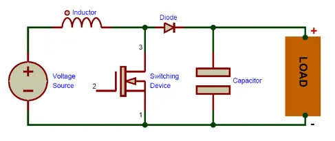
A boost converter (Step – Up Converter) is a DC – DC Power Converter that steps up the voltage (while stepping down current) from its input (supply) to is output (load). It is a class of switched mode power supply (SMPS) containing at least two semiconductors (a diode and a transistor) nd at least one energy storage element – a capacitor, an inductor, or a combination of two. To reduce the voltage ripple, filters made of capacitors (sometimes in combination with inductors) are normally added to such a converter’s output (load-side filter) and input (supply side filter).
A boost converter is one of the simplest types of switch mode converter. As the name suggests, it takes an input voltage and boost / increases it. All it consists – is an inductor, a semiconductor switch (MOSFET), a diode, a capacitor. It also needs a source of a periodic square wave. This is something as simple as a 555 timer or even a dedicated SMPS IC like the famous MC34063A IC.
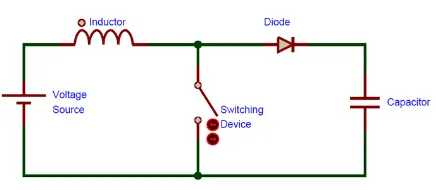
As you can see there are only few parts are required to make a boost converter. It is less cumbersome than an AC transformer or inductor. They are so simple because they were originally developed in the 1960s to power the electronics systems on an aircraft. It was requirement that these converters be as compact & as efficient as possible. The biggest advantage boost converters offer is their high efficiency- some of them can even go up to 99% i.e. 99% of an input energy is converted to useful output energy, only 1% is wasted.
HOW DOES A POWER CONVERTER WORK ?
Step I –
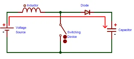
Here nothing happens, the output capacitor is charged to the input voltage minus one diode trap.
Step II –
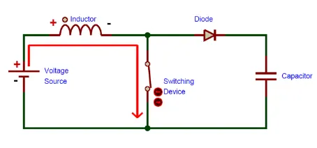
Now it’s time to run the switch ON. Our signal source goes high, turning ON the MOSFET. All the current is diverted to the MOSFET through the inductor, note that the output capacitor stays charged since it can’t discharge through the now back-based diode. The power source isn’t immediately short circuited, of course since the inductor makes the current ramp up relatively slow. Also the magnetic field builds up around the inductor. Note the polarity of the voltage applied across the inductor.
Step III –
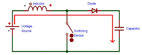
The MOSFET is turned OFF & The current in the inductor is stopped abruptly. The very nature of an inductor is to maintain smooth current flow; it doesn’t like sudden changes in current so it doesn’t like sudden turning OFF of the current. It responds to this by generating a large voltage with the opposite polarity of the voltage originally supplied to it using the energy stored it in the magnetic field to maintain that current flow.
If we forget the rest of the circuit elements and notice only the polarity symbols, we notice that the inductor now acts like a voltage source in series with the supply voltage. This means that the anode of the diode is now at a higher voltage than the cathode (remember the cap was already charged to supply voltage in the beginning) & is forward biased.
The output capacitor is now charged at a higher voltage than before, which means we have successfully stepped up a low DC voltage to a higher one.
Duty Cycle Control Signal Generation –
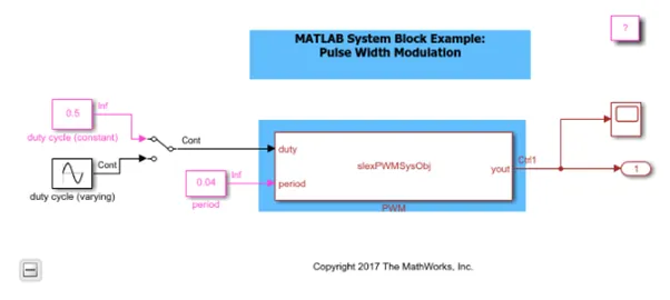
This example shows how to use MATLAB System block to generate Pulse Width Modulation (PWM) signals based on the input period and duty cycle signals by using controllable sample time and setNumTicksUntilNextHit.
In this example, MATLAB System block registers a controllable sample time so that it can schedule the next hit while changing the output value. In this example, the MATLAB System block has two input ports and one output port. The first input port is the duty cycle signal and the second input port is the period signal. The MATLAB System block has two block parameters: the amplitude of the generated PWM signal and the resolution of the controllable sample time.
In this example, the MATLAB System block demonstrates the use of the function: * createSampleTime(obj, 'Type', 'Controllable', 'TickTime', obj.Resolution) to register a controllable sample time in getSampleTimeImpl method. The resolution must be a positive finite integer that defines the fundamental step size that the MATLAB System block can schedule the next hit for this sample time.
MATLAB System Block demonstrates the use of the method: * setNumTicksUntilNextHit(obj, numTicks) to schedule the next hit of the controllable sample time. The next hit happens after t = t_current + numTicks * resolution. numTicks must be a positive integer. The MATLAB System block can use this method to schedule the execution of the controllable sample time in setupImpl and stepImpl.
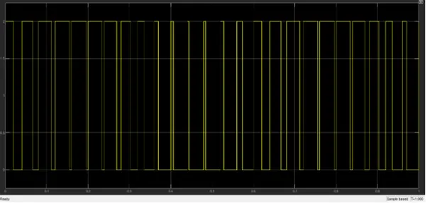
Results –
When Duty Cycle is 0.5 -

For sinusoidal Duty Cycle -
Boost Power Converter –
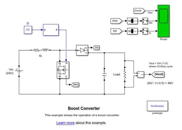
A boost converter is a DC/DC power converter which steps up voltage from its input (source) to its output (load). In continuous conduction mode (current through the inductor never falls to zero), the theoretical transfer function of the boost converter is:

where is the duty cycle.
In this example, the converter is feeding an RC load from a 24 V source and the PWM frequency is set to 20 kHz.
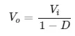
In continuous conduction mode (current through the inductor never falls to 0) & the theoretical transfer function of the boost converter is –
In this model the converter is feeding an RC load from a 24V source and PWM frequency is set to 20 KHz.
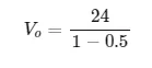
= 48
Result –
From Graph, V0 = 60V
Actual Duty Cycle –
= 0.6
Output –
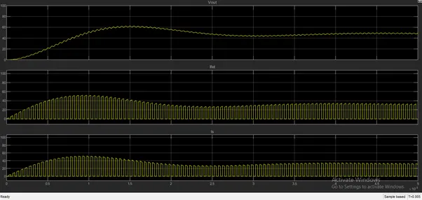
The Boost Converter which increases he input voltage to 70% of duty cycle to output voltage. In the result, we get the output voltage as 16V, by varying the duty cycle, the output voltage also varies but more than the input voltage which is also called Step_up Voltage.
- Make a comparison of Square Wave inverter output voltage with a sine modulated one.
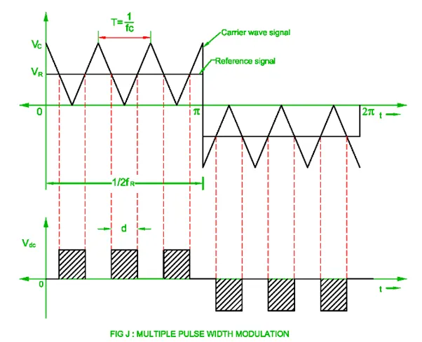
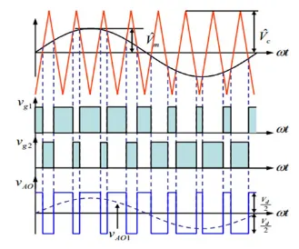
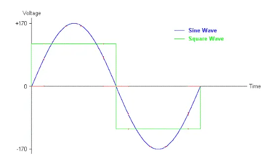
Sine wave Vs. Square Wave
Output voltage wave form of the true wave inverter is a pure sine wave which we get through utility usage in our home for the electric appliances. Pure wave of sine distortion is approx. 0, just like electricity obtained from company. But the square wave harmonics produces distortion which can destroy or damage our equipment while running on square wave. So pure sine wave is better than square wave.
Most of the time we use inductive loads in our homes and while using such loads we had to use pure sine wave. Because it runs faster with pure sine wave than square inductive. It can be Microwave oven, motor, cooler, etc. so Pure sine wave should be used for higher efficiency.
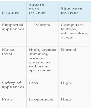
Sine wave reduces Audible and noise pollution while running electric appliances than the square wave inverters.
Sine wave inverter output is very close to the AC current but it is very pure form compared to square wave output. Many devices get heated up if you use square wave inverter and make humming noise too.
Modified Sine Wave Vs. Square Wave Inverter –
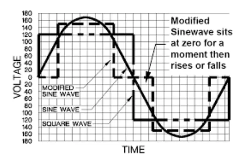
A modified sine wave inverter actually has a waveform more like square wave, but with an extra step. A modified sine wave inverter will work well with most equipment, although the efficiency or power of the equipment will be reduced.
Refrigerator motors, Pumps, Fans, etc. will use more power from the inverter due to lower efficiency. Most motors will use about 20% more power; this is because the fair percentage of a modified sine wave is of higher frequencies.
Some florescent lights won’t operate quite as bright, or some may buzz or operate by making annoying humming buzz sounds.
Appliances with electronic timers / digital clocks won’t operate correctly. Many appliances get their timing from the peak of the line power – basically the modified sine has a flat top rather than a peak and this may cause the occasional double trigger because the modified sine wave is rather noisier and rougher than pure sine wave, clocks and timers may run faster or not work at all.
Item such as bread makers and light dimmers may not work at all and in many cases appliances that use electronic temperatures control will not control- the most common examples are variable speed drills.
Sine wave inverter is very close to the AC current. It is very pure form compared to square wave output. Many devices get heated up if you use on square wave inverter and make humming noise too.
Though both outputs are made up of square waves only, the main difference is their duty cycle.
In former the duty cycle is constant throughout, while in the latter it changes many times within the one cycle.
The reference signal in the former is just the straight line while in the latter it is the wave which is well designed to produce sine modulated pulse width at the output.
- Explain the difference between VFD & Vector Control Drive. Can we use VFD method for the Induction Motor in EV application?
VFD -
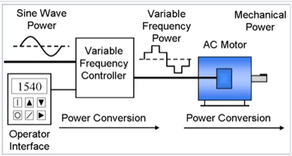
VFD is the type of motor controller that drives an electric motor by varying the frequency and voltage supplied to the electric motor. Other names to the VFD are Variable Speed Drive, Adjustable Speed Drive, Adjustable Frequency Drive, AC Drive, Micro Drive and Inverter.
VFDs are used in applications ranging from small appliances to large compressors. About 25% of the world’s electrical energy is consumed by electric motors in industrial applications. Systems using VFDs are more efficient than those using throttling controls of fluid flow, such as systems with pumps & fans. However, the global market penetration for all applications of VFDs is relatively small. Pulse Width Modulated VFDs when operated from a constant frequency power source (Typically 60 MHz) AC induction motors are fixed speed devices. A variable frequency drive controls the speed of an AC motor by varying the frequency supplied to the motor.
A standard VFD will sometimes be referred to as a “V/Hz” drive to differentiate it from a vector drive. It maintains the certain V/Hz Ratio to the motor at all times. For e.g. a 230 Vac, 60 Hz Motor wants to see a V/Hz Ratio of 3.83, when a V/Hz drive changes speed (frequency), it also changes the output voltage to keep the ratio constant so at 30 Hz (half speed), the same 230 Vac motor will only see 115 Vac output from the drive.
For most applications it works great as long as you operate from 6 to 60 Hz (10:1 speed range) below 6 Hz a motor a V/Hz type VFD can’t generate much torque, because at those low speeds, the V/Hz ratio to achieve max. torque is different than at higher speeds. If you try to run at those lower speeds with a V/ Hz drive, you will typically see the motor shaft ‘Cogging’ as it tries to run.
By using VFD we can get additional advantages as –
Reduced energy consumption & energy costs, increased production through tighter energy control, extended equipment life & reduced maintenance.
Vector Control Drive –
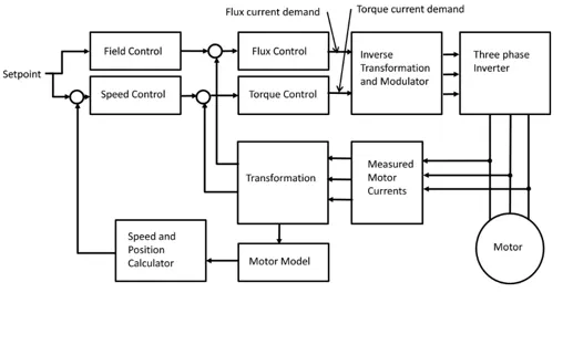
It is the Vector Sum of the 2 currents (1st & 2nd) in the stator that is solved for & by the drives in a Vector Drive application, Hence, it is called as Vector Drive.
Vector Control Drive is also called Field Oriented Control is a VFD control method in which stator current of 3 Phase AC electric motor are identified as 2 Orthogonal Components that can be visualized with Vector. One component defines the magnetic flux of the motor & the other is the torque. The control system of the drive calculates the corresponding current component from the flux & torque references given by drive’s specific speed control. Typically, proportional integral (PI) controllers re used to keep the measured current components at their reference values. The pulse-width modulation of the variable frequency drive defines the transistor switching according to the stator voltage references that are output of the PI controllers. FOC is used to control AC Synchronous and Induction Motors.
Blaschke introduced the principle of the vector control to realize the DC motor characteristics in an Induction Motor. He utilized decoupled control of torque and flux in the motor and gave the name Transvector Control. In D.C. Machine particularly, separately excited.D.C. motor, the filed flux is perpendicular to the armature flux. Being orthogonal, these 2 fluxes produce no net interaction to each other. Adjusting the filed current can be therefore control D.C. machine flux, and torque can be controlled independently of flux by adjusting the armature current. An AC machine isn’t so simple because the interactions between the stator & the rotor fields, whose orientations are not held at 900 but vary with operating conditions. We can obtain D.C. machine like performance in holding a fixed and orthogonal orientation between the fields and armature fields in an AC machine by orienting the stator current with respect to rotor flux so as to attain independently controlled flux and torque, such scheme is called Vector Control or FOC. Vector Control method is most commonly used method of speed control technique of an Induction Motor because it is superior transient response compared to other methods & its ability to enable independent torque and flux control. Generally, VFD uses Pulse Width Modulation Technique.
Vector drives can separately manipulate voltage and frequency to always produce the optimum V/Hz ratio for maximum torque. In this way Vector Drives can generate more starting torque and can provide full torque down to 1Hz. Or less. While V/Hz drives are limited to about 5-6 Hz.
There are 2 types of Vector Control Drives –
- Closed Loop.
- Open Loops/ Sensorless.
- Closed Loop – These require special motors with encoder feedback that provide motor shaft position info to the drive. The drive uses this information to constantly alter the V/Hz Ratio for maximum torque. This VFD is very high performance and very expensive.
- Open Loop / Sensorless – These work with standard motors, but because there is no encoder feedback the performance is not as good as Closed Loop but still much better than V/Hz drives. Instead of getting real time info from an encoder, a Sensorless vector drives estimates what is going on by creating a motor model within its software. This model is created using motor info that are entered in the user manual, along with the other info that the drive measures when it is connected to the motor.
Vector drives are (more accurately referred as ‘FOC’ Drives) don’t exactly solve for a V / Hz relationship. Rather, they solve for 2 specific currents within the stator simultaneously. The V/ Hz relationship solved implicitly according to the flux density from the vector sum of current components described below –
The 1st Current is the Magnetizing current, since there is no magnetic field within the rotor of the motor, it must be induced using electromagnetism (Hence Induction Motor) A DC motor is controlled in the stator to induce an electromagnetic filed in the rotor. As the rotor is turned this magnetic field is rotating synchronously with the rotor to maintain a static orientation of the magnetic field relative to the rotor.
The 2nd current is the torque producing current. This current is controlled in the stator to produce the electromagnetic field within the stator itself that is oriented with the 90 degrees to the magnetic fields simultaneously induced in the rotor as described above. As the intensity of the torque producing current increases, the torque applied to the rotor (ex. Motor Shaft) increases.
Can we use VFD method for the Induction Motor in EV application?
Yes, we can use VFD in EV application, but it is not used in industry as a Vector Control method.
VFD is a type of motor controller that drives an electric motor varying the frequency and voltage supplied to the electric motor. It regulates the speed of the 3 Phase Induction Motor by controlling the frequency and voltage of the power supplied to the motor.
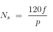
Since the no. of the pole is the constant then speed (Ns) can be varied by continuously changing the frequency, the faster the motor runs. If an application doesn’t require an electric motor to run at faster speed, the VFD can be used to ramp down the frequency and voltage to meet the requirements of the electric motor’s load. As the application’s motor speed requirements changes, the VFD can simply turn up or turn down the motor speed to meet the speed requirement.
Circuit –
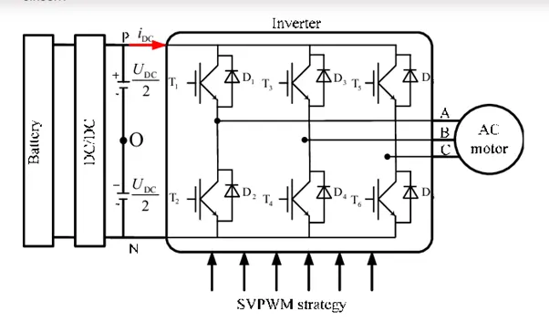
Now let’s say a steady 650 V is supplied to the battery and by controlling the switches (IGBTs) here strategically we can produce the required output
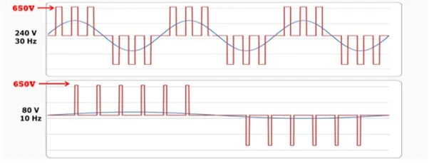
So as far as we have seen VFD control method of the inverter, the problem with the usage for 3 phase induction motor is that in a 3 phase induction motor the flux and current are interdependent and using VFD we can’t control them separately. But in Vector control method we can control the flux and current (that produces torque) independently.
As the basic principle of the VFD is –
To control the Torque & Flux independently we convert 3 Phase stator currents (La, Lb, Lc) to 2 phase currents using (Clarke & Park Transformation). And the 2 Phase currents are –
Flux producing component (Id) produces net flux in the motor.
Torque producing component (Lq) which produces torque in the motor.
Apart from independent control of torque and flux producing currents, Vector control method is more efficient than VFD, hence preferred in industries over VFD. VFD is most applicable for pumps & other small applications. In VFD flux and current are coupled to each other and the stator drop compensation were also their due to the coupled flux and current efficiency of the battery is low but the space vector pulse with modulation, the torque and flux are decoupled and also it can achieve to reference voltage and small switching losses. It can be most usable in Induction Motor for better performance. For EV, IM are mostly based on the performance and drive.